SYCLOPE EVASION How to use

Installation and starting instructions
Reference : EVA0000 Rev : 4
SYCLOPE EVASION®Controller for public swimming pools (Part 1)

General informations Page 2/48
Installation and starting instructions for SYCLOPE EVASION®
Parts of the general documentation
Part 1 : Installation and starting instructions
Part 2 : Programming instructions
Part 3 : Programming communication instructions
General information:
SYCLOPE Electronique 2014®Manual of the 07/05/2014 Rev 4
Professional Analyzers/Controllers for public swimming pools.
Product line EVASION®
Part 1: Installation and starting instructions (Ref : DOC0171)
Editor :
SYCLOPE Electronique S.A.S.
Z.I. Aéropole pyrénées
Rue du Bruscos
64 230 SAUVAGNON - France –
Tel : (33) 05 59 33 70 36
Fax : (33) 05 59 33 70 37
Email : syclope@syclope.fr
Internet : http://www.syclope.fr
© 2014 by SYCLOPE Electronique S.A.S.
Subject to modification
►

Contents Page 3/48
Installation and starting instructions for SYCLOPE EVASION®
I. General informations ......................................................................................................... 5
1) Applicability ...................................................................................................................... 5
2) FCC conformity ................................................................................................................. 6
3) Use of the document ......................................................................................................... 7
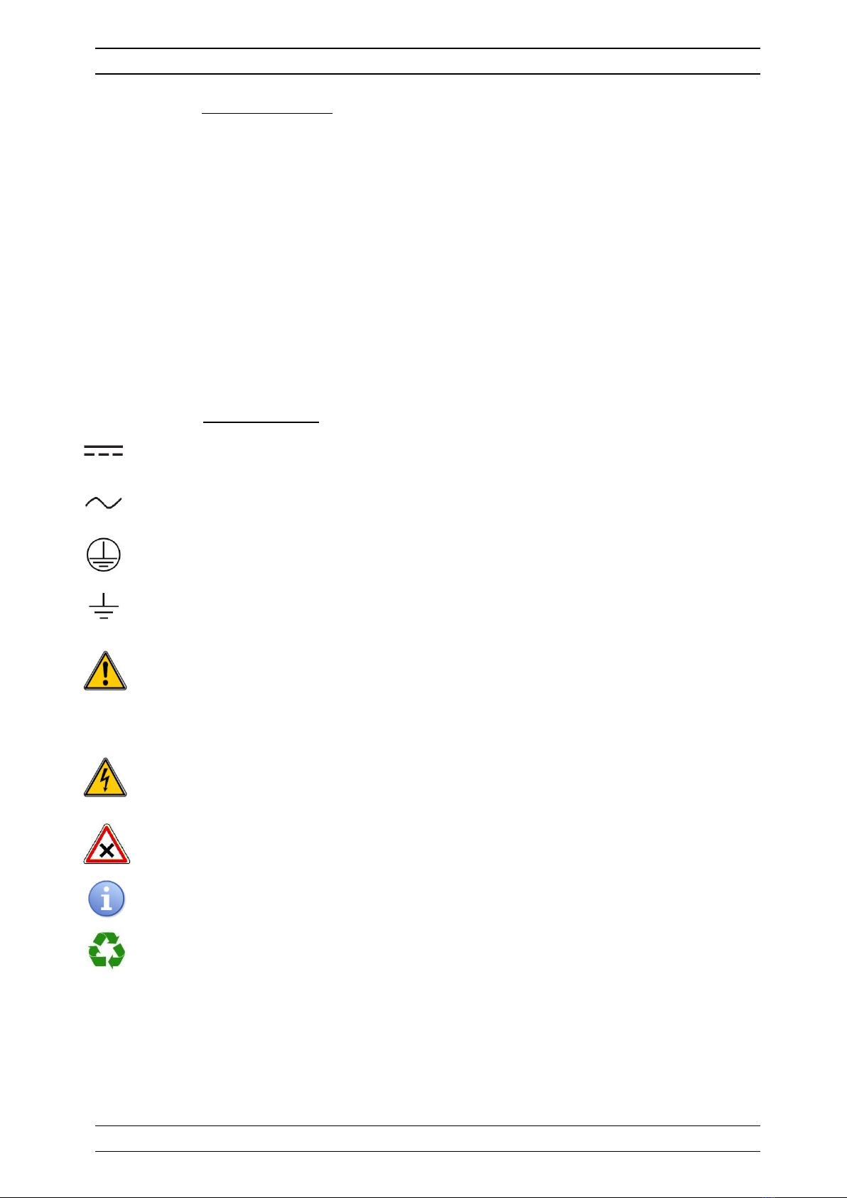
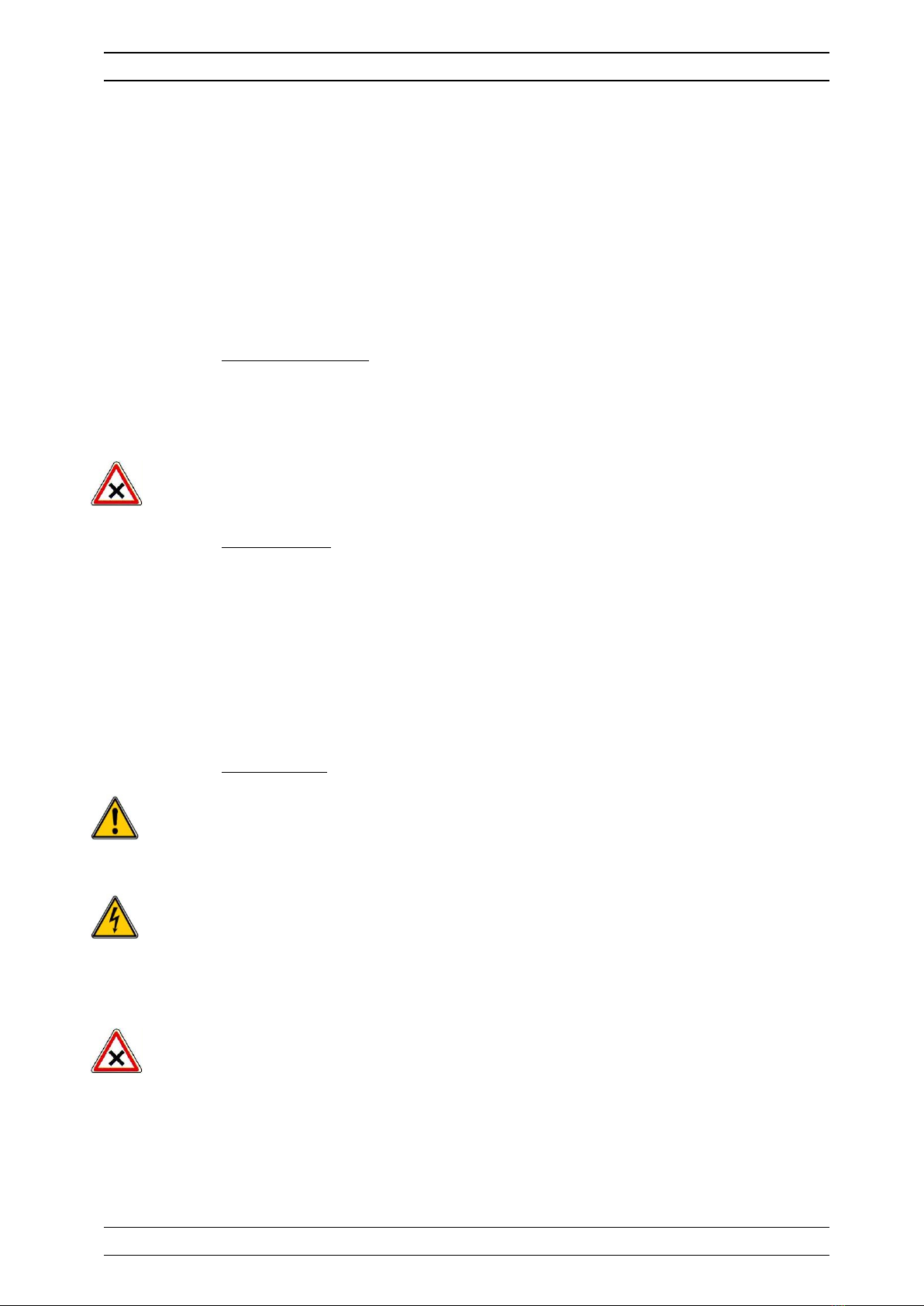
4) Symbols and signs............................................................................................................. 7
5) Storage and transport........................................................................................................ 8
6) Packaging ......................................................................................................................... 8
7) Warranty .......................................................................................................................... 8
II. Safety and environmental instructions................................................................................. 9
1) Use of the equipment ........................................................................................................ 9
2) User obligations ................................................................................................................ 9
3) Risk prevention ................................................................................................................. 9
4) Labelling and localization of the identification plate ............................................................10
5) Disposal and conformity....................................................................................................11
III. Technical specification and functions .................................................................................12
1) Technical specifications.....................................................................................................12
2) Main functions..................................................................................................................13
3) Type and range of measurements .....................................................................................14
IV. Installation and electrical connections ................................................................................16
1) Installation conditions.......................................................................................................16
2) Installation of the wall-mounted devices ............................................................................16
3) Electrical connections .......................................................................................................16
4) Primary electrical connections ...........................................................................................17
5) Connecting the power relay outputs free of potential..........................................................18
6) Connecting the measurement inputs..................................................................................18
7) Connecting the power supply to the special measuring cells or converters ...........................19
8) Connecting the analogical outputs .....................................................................................20
9) Connecting remote control inputs (CADx) ..........................................................................20
10) Connecting the flow control imputs....................................................................................20
11) Connecting the I+I-bus.....................................................................................................21
12) Connecting the printer onto RS232 output .........................................................................21
13) Connecting the RS485 communication port ........................................................................22
14) Connecting the MODEM phone ..........................................................................................23
15) Connecting the internal GSM Modem .................................................................................24
16) Connecting an external GSM MODEM.................................................................................24
17) Connecting a WIFI socket modem .....................................................................................25
18) Connecting an Ethernet socket modem..............................................................................25
19) Connecting the I2C communication port ............................................................................26
20) Infrared interface for remote control (IRC) ........................................................................26
V. General uses ....................................................................................................................27
1) Sampling on gravidity return line.......................................................................................27
2) Sampling between pump and filtering group ......................................................................28
VI. Automatic configurations...................................................................................................29
1) One circuit for ..................................................................................................................29
2) Two separated filtration circuits.........................................................................................30
VII. Introduction to the human-machine interface.....................................................................31
1) Display and control keypad ...............................................................................................31
2) Internal connections .........................................................................................................32
3) Connection terminal boards ..............................................................................................32
VIII. Starting the controller .......................................................................................................33
1) Setting an automatic configuration ....................................................................................33
2) Programming the real time clock (RTC) .............................................................................34
3) Adjusting the contrast and the backlight intensity of the display ..........................................34
4) Programming the setting points.........................................................................................35
5) Programming technical alarms ..........................................................................................36
6) Direct calibration of measurement sensors .........................................................................37
7) Selecting and programming display modes.........................................................................37
8) Symbols and statutes of working .......................................................................................40

Contents Page 4/48
Installation and starting instructions for SYCLOPE EVASION®
9) Starting regulation and dosing. .........................................................................................41
IX. Spare parts and accessories ..............................................................................................42
X. Maintenance.....................................................................................................................43
XI. Appendices : Connections. ................................................................................................44

General informations Page 5/48
Installation and starting instructions for SYCLOPE EVASION®
I. General informations
1) Applicability
The analyzer/controller of the SYCLOPE EVASION®range you have just purchased is an electronic
swimming-pool water management device. It has been carefully developed and manufactured to ensure
your greatest pleasure and peace of mind.
Its remarkable capacity for adapting to different conditions and sizes of public swimming pools means it
can be installed in the most difficult of environments where control of water treatment and swimming-
pool water regulation processes are decisive.
Designed according to the needs of the customer, the SYCLOPE EVASION®controller is equipped with
10 analogical inputs, 2 numeric inputs and 2 pulse inputs for specific sensors for treating swimming-pool
water and also include alarm functions and regulations with cyclic commands transmitted by means of six
configurable internal relays and 2x8 external relays to control temperature, pH, ORP (mV), active, free,
total chlorine, chloramines, active, free, total bromine for sea water and DBDMH / BCDMH bromines,
cyanuric acid, Ozone, PHMB, Turbidity and conductivity levels. It can combine and calculate 8 parameters
with these entries and use them as entire completive parameters.
Two ports, RS232 and RS485, for a printer and/or a computer link, allows communication by direct link or
phone modem or GSM/WIFI/Ethernet Modems to a desktop computer (PC) for filing and graphic
processing of the acquisition data.
EVACOM®and SYSCOM®software applications made by SYCLOPE Electronique S.A.S. have been
developed to perform these functions.
The simplicity of operation of the SYCLOPE EVASION®, the user friendliness and the remarkable
technical aspects of these controllers, will ensure you benefit from their many options, guaranteeing you
full control and supervision of the quality of the water in your swimming pool.
The following instructions contain all the information required for the installation, use and maintenance of
your new equipment.
Installation
Technical specifications
Commissioning instructions
Safety tips
If you would like to receive further information or if you encounter any difficulties not described in this
manual, please contact your usual retailer or else directly contact the sales department of SYCLOPE
Electronique S.A.S., either at the agency or at the office for your region, or the technical/quality
departments of our establishments. We will do everything in our power to help you and ensure you
benefit from our advice and know-how in the field of measurement and treatment of swimming-pool
water.
Contact : contact@syclope.fr

FCC Conformity Page 6/48
Installation and starting instructions for SYCLOPE EVASION®
2) FCC conformity
This device complies with Part 15 of the FCC rules. Operation is subject to
the following two conditions: (1) This device may not cause harmful
interference and (2) this device must accept any interference received
including interference that may cause undesired operation.
Instructions to Users: This equipment complies with the requirements of
FCC (Federal Communication Commission) equipment provided that the
following conditions are met.
This equipment has been tested and found to comply with the limits for a Class B digital device, pursuant
to Part 15 of the FCC Rules. These limits are designed to provide reasonable protection against harmful
interference in a residential installation. This equipment generates, uses, and can radiate radio frequency
energy and, if not installed and used in accordance with the instructions, may cause harmful interference
to radio communications. However, there is no guarantee that interference will not occur in a particular
installation.
If this equipment does cause harmful interference to radio or television reception, which can be
determined by turning the equipment off and on, the user is encouraged to try to correct the interference
by one or more of the following measures:
Reorient or relocate receiving antenna,
Increase the separation between the device and receiver,
Connect the device into an outlet on a circuit different from that to which the receiver is
connected,
Consult the dealer or an experienced radio/TV technician for help.
Changes or modifications not expressly approved by the party responsible for compliance could void the
user's authority to operate the equipment.
Remark :
In order to maintain compliance with the limits of a Class B digital device, use a recommended
shielded cable when connected to this device as describe in the present notice. Using a bad
cable or a cable not connected to the ground voids the user's authority, which is granted by
the Federal Communications Commission, to operate this equipment.

General information Page 7/48
Installation and starting instructions for SYCLOPE EVASION®
3) Use of the document
Please read carefully the entire document before starting the installation and the commissioning of the
controller device, in order to ensure the safety of swimmers, users and equipments.
The information provided in this document must be strictly observed. SYCLOPE Electronique S.A.S.
declines all responsibility in cases where failure to comply with the instructions of this documents.
The following symbols and pictograms will be used to facilitate reading and understanding of these
instructions.
Information
Action to be taken
Item of a list or catalogue
4) Symbols and signs
Identification of a continuous voltage or current.
Identification of an alternative voltage or current.
Protective ground.
Functional ground.
Risk of injury or accident. Identifies a warning concerning a potentially dangerous risk. The
documentation must be consulted by the user with each time the symbol is notified. If the
instructions are not respected, this presents risks of death, physical injuries or property
damages.
Electric hazard. Identifies a warning statement relative to a mortal electric danger. If the
instructions are not strictly respected, this implies an inevitable risk of physical injuries or
death.
Risk of incorrect operation or damage for the device.
Comment or particular information.
Recyclable element.

General information Page 8/48
Installation and starting instructions for SYCLOPE EVASION®
5) Storage and transport
It is important to store and to transport the SYCLOPE EVASION®controller in its original
packaging in order to minimize risk of damage.
Furthermore, the package must be stored in an environment that is protected against
humidity and exposure to chemical products.
Environmental conditions for transport and storage:
Temperature: -10 °C to 70 °C
Air humidity: Maximum of 90% with no condensation
6) Packaging
The controller is delivered without electrical power cable.
The pre-drilled holes of the box are drilled and equipped with according electrical glands in
compliance with IP65 level protection. The cables must be adapted to the electrical glands
for respecting the level of protection.
Content of the packaging:
One analyser/controller SYCLOPE EVASION®
Installation and starting instruction notice
Programming notice
Communication notice (Option)
7) Warranty
The warranty is provided according to the terms of our general conditions of sale and delivery as long
as the following conditions are met:
Use of the equipment according to the instructions of this notice
No modifications of the equipment which may modify its behavior and no incorrect
manipulation
Respect for the electrical safety conditions
Consumable material is no longer covered by the warranty when in use.

Safety and environmental instructions Page 9/48
Installation and starting instructions for SYCLOPE EVASION®
II. Safety and environmental instructions
Please:
Read this manual carefully before the unpacking, the installing or the commissioning of this
equipment
Take into account all the hazards and of recommended precautionary measures
The failure to respect these procedures can result in serious injury to users or damaging the device.
1) Use of the equipment
The SYCLOPE EVASION®controller has been designed to measure and control temperature, pH, Redox
potential, chlorine (or bromine), Ozone, PHMB, flow, Turbidity and Conductivity by means of sensors and
controls of suitable actuators in the context of the possible uses described in this manual.
All other uses are considered to be non-conforming and must therefore be forbidden. SYCLOPE
Electronique S.A.S. will not be responsible in any case for any damage that result from such uses.
2) User obligations
The user undertakes not to allow its employees to work with the SYCLOPE EVASION®controller
described in this manual unless they:
Are aware of the fundamental instructions relating to work safety and prevention of accidents.
Are trained in the use of the device and its environment.
Have read and understood these instructions, warnings and manipulation rules.
3) Risk prevention
The installation and connection of the SYCLOPE EVASION®controller should be only performed
by a specialized personnel and qualified for this task.
The installation must comply with the current safety standards and instructions!
Before opening the controller or manipulate the relay outputs, always remember to switch-off the
primary power supply!
Never open the controller when it is powered on!
Maintenance operations and repairs should be only performed by trained and specialized
personnel!
Take care when choosing the location for installing the controller!
The controller should not be installed in a hazardous environment and should be protected
against splashing with water or chemical products. It should be installed in a dry, well-ventilated
and isolated location.

Safety and environmental instructions Page 10/48
Installation and starting instructions for SYCLOPE EVASION®
Make sure that the chemical sensors used with this controller correspond well to the chemicals
used. Refer to the individual technical note of each sensor. Chemistry of water is very complex,
in case of doubt, contact immediately our engineering service or your approved
installer/reseller.
Chemical sensors are sensitive elements using consumable parts. They must be supervised,
maintained and calibrated regularly using specific calibrator systems not-provided with this
equipment. In the event of defect, a surplus possible hazard of chemical injections can be
noted. In the doubt, a service contract must be taken near your reseller/installer or failing this
near our engineering services. Contact your approved installer/reseller or our business service
for more information.
4) Labelling and localization of the identification plate
Label of the manufacturer
Particular risks. Read the manual
Model of the product
Product which can be recycled
Reference of the product
Limitation of dangerous substances
Range of power supply
EC compliance
Values of the maximum current
Country of the manufacturer
Class of protection
Manufacturer square code
Identification of the manufacturer
Conformity with the FCC part 15 Class B
Serial number
Identification plate
1
2
3
4
5
6
8
11
12
7
14
13
EVASION
Ref:EVA 0000
90 - 240VAC 50/60Hz
www.syclope.fr Made in France
0,3 - 0,16A
IP65
S/N: 13044217
This device compiles with the Part.15 of the FCC rules. Operation is subject to the following
two conditions: (1)Thisdevicemaynotcauseharmfulinterference, and(2) thisdevice must
acceptanyinterferencereceived,includinginterference thatmaycauseundesiredoperation
9
10
15
1
2
3
4
5
6
7
8
9
10
11
12
13
14
15

Safety and environmental instructions Page 11/48
Installation and starting instructions for SYCLOPE EVASION®
5) Disposal and conformity
The recyclable packaging of the SYCLOPE EVASION®equipment must be disposed of according to
current regulations.
Elements such as paper, cardboard, plastic or any other recyclable elements must be taken to a
suitable sorting center.
According to European directive 2002/96/EC, this symbol means that as of 12 August 2005
electrical appliances cannot be thrown out together with household or industrial waste.
According to current regulations, consumers within the European Union are required, as of this
date, to return their used devices to the manufacturer, who will take care of disposing them at
no extra expense.
Collecting and recycling of the internal batteries: According to the European directive
2006/66/CE, this symbol indicate that until September, 26th 2006, used batteries, accumulators
and waste materials using dangerous heavy metals as lead (pb), cadmium(Cd) or mercury (Hg)
must be collected separately by the manufacturer or by an accredited agency.
According to European directive 2002/95/EC, this symbol means that the SYCLOPE
EVASION®controller is designed in compliance with the restrictions on hazardous substances.
According to low-voltage directive (2006/95/EC) and the electromagnetic compatibility directive
(2004/108/EC), this symbol means that the device has been designed in compliance with the
previously cited directives.
In accordance with part 15 of the FCC regulation (Federal communications commission), this
symbol indicates that the device was tested and approved under the respect and the conditions
of the limits for a Class B digital device.

Technical characteristics Page 12/48
Installation and starting instructions for SYCLOPE EVASION®
III. Technical specification and functions
1) Technical specifications
General characteristics
Type
Specification(s)
Markers(s)
Consumption
0,3Amp. Max. (90VAC) to 0,15Amp. Max. (240VAC)
-
Power supply requirements
Between 90V to 240V +/-10%
-
Overvoltage Category
Category II
-
Temporary overvoltage
Accept temporary over voltages from power line.
-
Electric protection
Glass 5x20 time-lag 315 mA fuse
F5
Internal battery
Ni/MH battery pack 12V 600 to 1300mA/h Max.
-
Operating temperature (ºC)
-5°C to 45°C
-
Storage temperature (ºC)
-10°C to 60°C
-
Humidity
Max. 90% without condensation
-
Case material
ABS or Polycarbonate (UL/CSA Version)
-
Case dimensions
Length : 320 mm (12,6 Inches)
Width : 260 mm (10,2 Inches)
Height : 129 mm (5,1 Inches)
-
Weight of the case
3 kg
-
Protection rating
IP 65
-
Display
LCD 128x240 with blue backlight
-
Inputs
Measurement inputs
10x powered analogue 4…20 mA inputs (12V)
E1 to E10
Control or flow inputs
2x programmable impulse inputs in « control On/off » or
flow meter function.
CAD1 and
CAD2
Numeric entries
2 numerical inputs for Cyanuric Acid sensor
E19 à E20
Outputs
Relay outputs
6x relay outputs, contacts free of potential.
Max. 5Amp. / 250 VAC
Relay1 to
Relay6
Analogue outputs
6x Analogue outputs 0/4…20 mA Max 500 Ω
SA1 to SA6
Printer output
1 RS232 Printer port type
SV3
DC power outputs
2x 12VDC power supply outputs for powering electronic
measurement cells. Max 1A together
12V
Communications
RS485 Bus
1x RS485 communication port
RS485
I+I-Bus
1x Serial communication port for external displays
I+I-
I2C Bus
1x I2C serial communication port for external modules
LDA/LCL
Socket Modem (Optional)
1x Socket modem place for phone/WIFI/GSM/Ethernet
Phone line

Technical characteristics Page 13/48
Installation and starting instructions for SYCLOPE EVASION®
2) Main functions
Main functions
Function
Specification(s)
Comment(s)
Regulation mode
On/off, P, PI, PID, Auto configuration
Power outputs for treatment in %
Relay cycle time for injection 240s.
Actuator type
Relay outputs - free of potential
Analogue outputs 0/4…20mA or
20…0/4mA
Impulse drive capability (With internal
relays only)
Control with on/off with hysteresis or
with cycle width modulation. (CWM)
Control from 0 to 100% of programmed
scale.
Control with PWM from 0 à 120 cps/mn
Direction
Up and/or down function(s)
Alarms
Low, high and technical alarms
Expressed in real measurement values
Control of top and bottom thresholds.
Closed-loop control
Remote control
Flow control
Level control
Closed-loop control of injections with an
external contact (filtering, for example)
or with control of water circulation.
Timers
Programming of operating time intervals
Option of 4 different weekly time
intervals.
Chemical
computations
Chemical computation between selected
entries.
8 computing
Configuration
Choice of standard configuration
Auto configuration with standard list
Maintenance
Maintenance helper
Control of dosing actuators
Recording
Data recorder
Data and event tracking
Extension modules
2 x 8 Relay modules
2 x 8 Analogue 0/4…20 mA modules
Driven by I2C bus.

Technical characteristics Page 14/48
Installation and starting instructions for SYCLOPE EVASION®
3) Type and range of measurements
Measurements and controls
Parameters
Measurement ranges
Precision
T°C
-5 to 45°C
± 0,5 %
0 to 100°C
± 0,5 %
pH
0 to 14 pH
± 0,5 %
-15,1 to 1 pH
± 0,5 %
Redox (ORP)
0 to 1000 mV
± 0,5 %
0 to 1500 mV
± 0,5 %
Active chlorine
0 to 1 ppm
± 0,5 %
0 to 2 ppm
± 0,5 %
0 to 5 ppm
± 0,5 %
0 to 10 ppm
± 0,5 %
0 to 20 ppm
± 0,5 %
Free chlorine
0 to 1 ppm
± 0,5 %
0 to 2 ppm
± 0,5 %
0 to 5 ppm
± 0,5 %
0 to 10 ppm
± 0,5 %
0 to 20 ppm
± 0,5 %
Total chlorine
0 to 1 ppm
± 0,5 %
0 to 2 ppm
± 0,5 %
0 to 5 ppm
± 0,5 %
0 to 10 ppm
± 0,5 %
0 to 20 ppm
± 0,5 %
Active bromine
0 to 1 ppm
± 0,5 %
0 to 2 ppm
± 0,5 %
0 to 5 ppm
± 0,5 %
0 to 10 ppm
± 0,5 %
0 to 20 ppm
± 0,5 %
Free bromine
0 to 1 ppm
± 0,5 %
0 to 2 ppm
± 0,5 %
0 to 5 ppm
± 0,5 %
0 to 10 ppm
± 0,5 %
0 to 20 ppm
± 0,5 %
BCDMH
0 to 1 ppm
± 0,5 %
0 to 2 ppm
± 0,5 %
0 to 5 ppm
± 0,5 %
0 to 10 ppm
± 0,5 %
0 to 20 ppm
± 0,5 %
Ozone
0 to 1 ppm
± 0,5 %
0 to 2 ppm
± 0,5 %
PHMB
0 to 20 ppm
± 0,5 %
0 to 50 ppm
± 0,5 %
0 to 100 ppm
± 0,5 %
Cyanuric acid
0 to 100 ppm
± 0,5 %
0 to 300 ppm
± 0,5 %
Conductivity
0 to 1000 µs
± 0,5 %
0 to 2000 µS
± 0,5 %
0 to 5000 µs
± 0,5 %
0 to 1 ms
± 0,5 %
0 to 10 mS*
± 0,5 %
0 to 50 mS*
± 0,5 %
0 to 100 mS*
± 0,5 %

Technical characteristics Page 15/48
Installation and starting instructions for SYCLOPE EVASION®
Measurements and controls
Salinity
0 to 12 g/l
± 0,5 %
0 to 32 g/l
± 0,5 %
0 to 72 g/l
± 0,5 %
Turbidity
0 to 1 NTU
± 0,5 %
0 to 2 NTU
± 0,5 %
0 to 5 NTU
± 0,5 %
0 to 10 NTU
± 0,5 %
0 to 50 NTU
± 0,5 %
0 to 100 NTU
± 0,5 %
0 to 200 NTU
± 0,5 %
0 to 500 NTU
± 0,5 %
0 to 1000 NTU
± 0,5 %
Flow rate ratio
0 to 9999 liters/hour
0 to 999,9 m3/hour
*Option under development

Installation and electrical connections Page 16/48
Installation and starting instructions for SYCLOPE EVASION®
IV. Installation and electrical connections
1) Installation conditions
To guarantee the user safety and to ensure correct operation of the controller, please observe
the following installation instructions:
Install the controller in a dry location,
The controller must be protected against rain, frost and direct sunlight,
The room temperature must range between 0°C and 50°C, with no condensation,
Choose an installation location free from vibration, on a suitable support and with no
deformation.
If these instructions are not observed:
The controller risks to be damaged,
The measurements can be disrupted,
The warranty is not applicable!
2) Installation of the wall-mounted devices
Before performing the installation and electrical connections, switch-off the power supply!
The rating of IP65 is only guaranteed when the cache of the electric part and the closure of the
front face are closed and when the cable glands match to the diameters of the cables and are
correctly sealed.
Drill three 5-mm holes according to the following drilling plan
Insert the 5-mm plugs using a hammer
Insert the upper screw (top screw) first without completely tightening it
Insert the lower screws and tighten them
Tighten the upper screw
Use a spirit level to check for correct and accurate fixing to the wall.
3) Electrical connections
The electrical installation must be performed in accordance with current rules by an authorized
personnel!
A 30 mA differential circuit must be installed!
A circuit-breaker of maximum 10 Amp must be installed near the controller and easily accessible
to stop the main power. It must be identified as a circuit-breaker for the controller!
Before performing the connections, remember to turn off the power!

Installation and electrical connections Page 17/48
Installation and starting instructions for SYCLOPE EVASION®
Use core cables if possible!
If not possible, always use a special wiring tip to be sure that the wires do not make a contact
together!
Protect the wirings by using electrical clamps.
The controller must be connected to the main recirculation pump by means of the "remote
control" input (CAD) to disallow functionality in the case of the main pump being stopped.
a) Internal protection
The controller is protected by a 5x20 315mA time-lag glass fuse and by a varistor against voltage surges
of 275 V.
Reference
Name
FUS5X20T315
5x20 315 mA time-lag glass fuse
In the event of the fuse blown, check that the card is not burnt out. If this is the case, the
complete card must be changed!
In the event of destruction of the varistor, please return the controller to our technical
department for assessment!
b) Internal protection
The SYCLOPE EVASION®controller is equipped with Cd/Ni 12 Volts 700 mA/h (Old model) or Ni/MH 12
volts 1300 mA/h internal battery to assume the good working of the sensors during a short power down.
The capacity of the battery and his recharge duration time determine the time of working under battery
mode.
During power-on, an internal electronic power switch connects automatically the internal battery to the
recharge circuit. This switch maintains the power supply as long as the battery is charged and switches-
off the controller before complete discharge.
The internal battery of the controller must be changed by an authorized technician.
Contact your after-sell service or your reseller.
Use only the recommended battery. In case of using another type of battery, the warranty
will not be taken by SYCLOPE Electronique.
Do not invert the wires when connecting!
Do not use any external charger to recharge the battery.
Reference
Name
BAT1206
Battery 12V 0,6 A/h
BAT1213
Battery 12V 1300mAh Ni/MH with safety connector
The battery must be recycled according to the environmental rules!
4) Primary electrical connections
The SYCLOPE EVASION®controller uses an internal switching power module. This
particularity can be used with a power line of 90 to 250V 5/60Hz without any disturbance.

Installation and electrical connections Page 18/48
Installation and starting instructions for SYCLOPE EVASION®
Use a 3-points 1.5 mm2cable to wire the power supply. Ground cable must be connected
firstly
Strip the 3 wires for 7 mm.
Pass the 3-point cable through a cable gland.
Wire the live to 1 and the neutral to 2 of the sector terminal block B1.
Wire the earth to screw contact with the help of an M4 eyelet terminal.
Tighten the cable gland to ensure tightness.
The controller does not have its own independent power switch. It is directly powered when
connected to the mains.
5) Connecting the power relay outputs free of potential
The power relay outputs, free of potential, are used to control the various measured or computed
parameters. Relays OUT1 to OUT6 are fully programmable (On/off function, width modulation, pulse
modulation or 3 points actuation) with all parameters using by the controller.
In case of use the automatic configuration, all power relays will be affected to a specific function (see
table automatic configuration Chap VI.).
6) Connecting the measurement inputs
The analogue inputs are used for acquiring multiple measurement sensors or special measuring cells
using the 4…20mA loop technology.
The measurement entries of the controller are self-powered (12V) and must never be used with
an external power supply!
The entries of the controller are not insulated between them!
You must use unconditionally the appropriate special measuring cells or converters to be sure
that each connected sensor works properly.
Warranty repairs will not be accepted in the event of failing to observe these instructions!
R : Rest
C : common
T : Task
90…240V
50/60Hz
Line
90…240V
50/60Hz
Line
Earth

Installation and electrical connections Page 19/48
Installation and starting instructions for SYCLOPE EVASION®
Please, respect the polarities when connecting all the wires of the external measuring cells or of
the converters onto the controller inputs. The external power supply (12V DC) needed is given
by the controller on “+12V” outputs.
When using the automatic configuration option of the controller, all the corresponding inputs
are defined according to the “Factory” setting. (See chap. VI : Automatic configuration of this
manual)
7) Connecting the power supply to the special measuring cells or converters
To work properly, all special measuring cells or all special converters of SYCLOPE products must be
powered by the +12VDC output generated by the controller.
Do not invert the power supply polarity!
Red wire on the +
Brown wire on the -
Special case when connecting a sensor with an active analog output (powered) :
+of the active output (sensor) -of the input (-Ex+)
-of the active output (sensor) -of the power (-12V+)
Example beside with E6 input

Installation and electrical connections Page 20/48
Installation and starting instructions for SYCLOPE EVASION®
8) Connecting the analogical outputs
The analogue outputs of the controller are used to forward information to a central unit or to control a
dosing unit by means of a signal of 0/4 - 20mA or 20…0/4mA.
The analogue outputs of the controller are fully configurable. Therefore, you can assign an output to any
measured or calculated parameter and you can use it for control or transfer operations.
If you use the automatic configuration menu, all the analogical outputs will be defined according to the
“Factory” setting. (See chap. VI : Automatic configuration of this manual).
9) Connecting remote control inputs (CADx)
The SYCLOPE EVASION®controller has two remote control inputs (CAD1 and CAD2) which stops the
dosing units. These inputs are either an open/closed contact input or a pulse control input used in a
subservient manner to the main circulation pump of the filtration system.
It is imperative to enslave the controller to the switch of the filtering group’s motor to prevent
damages caused by chemical overdoses!
The remote control inputs CAD1 and CAD2 are designed to receive a NO contact (normally
open), a NC (normally connected) or a pulse control drive (Open collector or free-potential
switch).
10) Connecting the flow control imputs
The SYCLOPE EVASION®controller has 2 fixed inputs (T°C and pH) and 8 programmable analogue
inputs where each of them can be programmed as a flow control input (FCI) used to check the presence
of circulating water in the measurement cells. This input is designed to receive either an analogue level
sensor (4…20mA), either a flow switch control.
Opened switch : Detection activated by open contact (Normally opened)
Closed switch : Detection activated by closed contact (Normally closed)
Analogue : Detection realized by 4-20 mA current loop.
Other manuals for EVASION
1
Table of contents
Other SYCLOPE Lighting Equipment manuals
Popular Lighting Equipment manuals by other brands

Chroma
Chroma Color Force 12 user manual

Robe
Robe ColorSpot 250 AT Service manual

Good Earth Lighting
Good Earth Lighting UC1270-WHG-12LFC-G INSTALLATION PROCEDURE

Future light
Future light MH - 640 user manual

Ultradent Products
Ultradent Products VALO GRAND manual

Prilux
Prilux Energy TECH RGB RF quick start guide

Artika For Living
Artika For Living Mezzo OUT-ME-MBJ instruction manual

Flash professional
Flash professional P7110027 manual

Light & Motion
Light & Motion CLx owner's manual

Osram
Osram Claypaky MINI XTYLOS HPE User information

Genaray
Genaray SSL-836 user manual

Sensio
Sensio SE9080HD installation instructions