ECI CabLite ECO Series User manual


Cablite ECO Installation Manual Rev 4.0
Electronic Controls, Inc.
7073 North Atlantic Ave. Cape Canaveral, FL 32920
800-633-9788
www.eciamerica.com P a g e | 2
REV
DATE
DESCRIPTION
1.0
10/28/2013
Initial release
2.0
3/7/2014
Updated the manual
3.0
7/8/20014
Added Dimming/Emergency board wiring
4.0
3/8/2017
New Manual format re-write
4.1
1/17/2018
Added new logo and drawings with 10k pot and service loops

Cablite ECO Installation Manual Rev 4.0
Electronic Controls, Inc.
7073 North Atlantic Ave. Cape Canaveral, FL 32920
800-633-9788
www.eciamerica.com P a g e | 3
Table of Contents
1Introduction...........................................................................................................................................4
2Warning and Disclaimer .......................................................................................................................4
3Trademarks ...........................................................................................................................................4
4Conventions Used.................................................................................................................................4
5Safety Information................................................................................................................................5
6System Overview..................................................................................................................................6
6.1 Downlights....................................................................................................................................6
6.1.1 ECO Downlight Specifications.............................................................................................6
6.2 CabLite ECO.................................................................................................................................6
6.3 CabLite ECO with Dimming Option ............................................................................................7
6.3.1 Dimmer Board.......................................................................................................................7
6.4 CabLite ECO with Dimming and Emergency Lighting Option....................................................8
6.4.1 CabLite ECO Emergency Board Connections......................................................................8
6.4.2 CabLite Emergency Board LEDs .........................................................................................9
7Installation.............................................................................................................................................9
7.1 Flat Bezel Downlight Dimensions..............................................................................................10
7.2 Raised Bezel Downlight Dimensions .........................................................................................10
7.3 CabLite ECO Wiring Diagram ...................................................................................................11
7.4 CabLite ECO w/ Dimming Wiring Diagram..............................................................................11
7.5 CabLite ECO w/ Dimming & Emergency Wiring......................................................................12
8Trouble Shooting ................................................................................................................................14
8.1 One Light Does Not Turn On .....................................................................................................14
8.2 Lights Do Not turn On (CabLite ECO).......................................................................................14
8.3 Lights Do Not Turn On (CabLite ECO w/ Dimming and Dimming/Emergency)......................14
8.4 No Emergency Lights with AC loss (Emergency light option)..................................................14
8.5 Designated Emergency Lights Do Not Light with AC Power (Emergency light option)...........14

Cablite ECO Installation Manual Rev 4.0
Electronic Controls, Inc.
7073 North Atlantic Ave. Cape Canaveral, FL 32920
800-633-9788
www.eciamerica.com P a g e | 4
1Introduction
This manual is intended for facilitate the installation of CabLite® ECO lighting system manufactured by
Electronic Controls Inc. The audience of the material included in this manual is for certified installation
personnel. The CabLite® ECO lighting system complies with modern performance specifications and
meets or exceeds code requirements. Installation and adjustments must meet local, state and national
codes.
2Warning and Disclaimer
Thank you for purchasing equipment from ECI America, INC. We want your new equipment to operate
safely. Anyone who installs or uses this equipment should read this publication (and any other relevant
publications) before installing or operating the equipment.
To minimize the risk of potential safety problems, you should follow all applicable local and national
codes that regulate the installation and operation of your equipment. These codes vary from area to area
and usually change with time. It is your responsibility to determine which codes should be followed, and
to verify that the equipment, installation and operation is in compliance with the latest revision of these
codes.
At a minimum, you should follow all applicable sections of the National Fire Code, National Electrical
Code, ASMEA17.1 Safety code for Elevators and Escalators and the codes of the National Electrical
Manufacturer’s Association (NEMA). There may be local regulatory or government offices that can also
help determine which codes and standards are necessary for safe installation and operation. Equipment
damage or serious injury to personnel can result from failure to follow all applicable codes and standards.
We do not guarantee the products described in the publication are suitable for you particular application,
nor do we assume any responsibility for your product design, installation or operation.
Our products are not fault-tolerant and are not designed, manufactured or intended for use or resale as
online control equipment in hazardous environments requiring fail-safe performance, such as in the
operation of nuclear facilities, aircraft navigation of communication systems, air traffic control, direct life
support machines or weapon systems in which the failure of the product could lead directly to death,
personal injury, or severe physical or environmental damage (“High Risk Activities”). ECI America, Inc.
specifically disclaims any expressed or implied warranty of fitness for High Risk Activites.
This publication is based on information that was available at the time it was printed. WE reserve the
right to make changes to the products and/or publications at any time without notice and without any
obligation.
3Trademarks
All trademarks or registered product names appearing in this document, as they pertain to Electronic
Controls, Inc., are the exclusive property of Electronic Controls, Inc.
4Conventions Used

Cablite ECO Installation Manual Rev 4.0
Electronic Controls, Inc.
7073 North Atlantic Ave. Cape Canaveral, FL 32920
800-633-9788
www.eciamerica.com P a g e | 5
When you see the “notepad” icon in the left-hand margin, the paragraph to its
immediate right will be a special note. Notes represent information that may make
your work quicker and more efficient. The word NOTE: in boldface will mark the
beginning of the text.
When you see the “exclamation point” icon in the left hand margin the paragraph
to its right will be a warning. The information could prevent injury, loss of
property, or even death in extreme cases. Any waring in this document should be
regarded as critical information that should be read in its entirety. The word
WARNING: in boldface will mark the beginning of the text.
5Safety Information
Know the safety hazards related to any procedure you are about to perform.
Know what equipment has been specified for each specific contact and know
what tools and materials you should plan to have available. Before connecting
electrical wiring, take precautions to prevent accidents from happening to
yourself and others around you.
ALWAYS CONSIDER SAFTY FIRST!
•Wear a hard hat when working in the hoist way.
•Wear safety glasses or goggles when using power tools
•Always wear protective gloves when installing or removing access covers,
conduits, wireway or electrical devices.
•When working on car canopy, always be aware of where the sides of the car are
located.
•Use properly grounded cords and power equipment (ground fault circuit
interrupters).
•Make sure there are proper clearances in hoist way between the car and other
devices. Before connecting wiring, cover sharp edges to keep hands and arms
from being cut.
•Always know where other people are and how the elevator wiring can affect
their safety.
•Safety lock and tag out procedures are always required before performing and
kind of service, repair, adjustment, lubrication or inspection of power equipment.
•To reduce the danger of electrical shock, always make sure electrical
connections are secure. Also make sure no bare wires are exposed after pulling
cable.
•Use a circuit tester to be certain the circuit is not active before touching it.
Cablite ECO Installation Manual Rev 4.0
Electronic Controls, Inc.
7073 North Atlantic Ave. Cape Canaveral, FL 32920
800-633-9788
www.eciamerica.com P a g e | 6
6System Overview
CabLite® ECO is a general downlighting system for use in passenger, residential and freight elevator
cabs operating from one to twelve downlight. CabLite® ECO high output, long life low voltage LED
downlights provide general interior lighting that meets or exceeds ASME A17.1, local, state and federal
codes.
There are 3 options for the CabLite ECO system:
•ECO
•ECO with dimming
•ECO with dimming and emergency lighting
6.1 Downlights
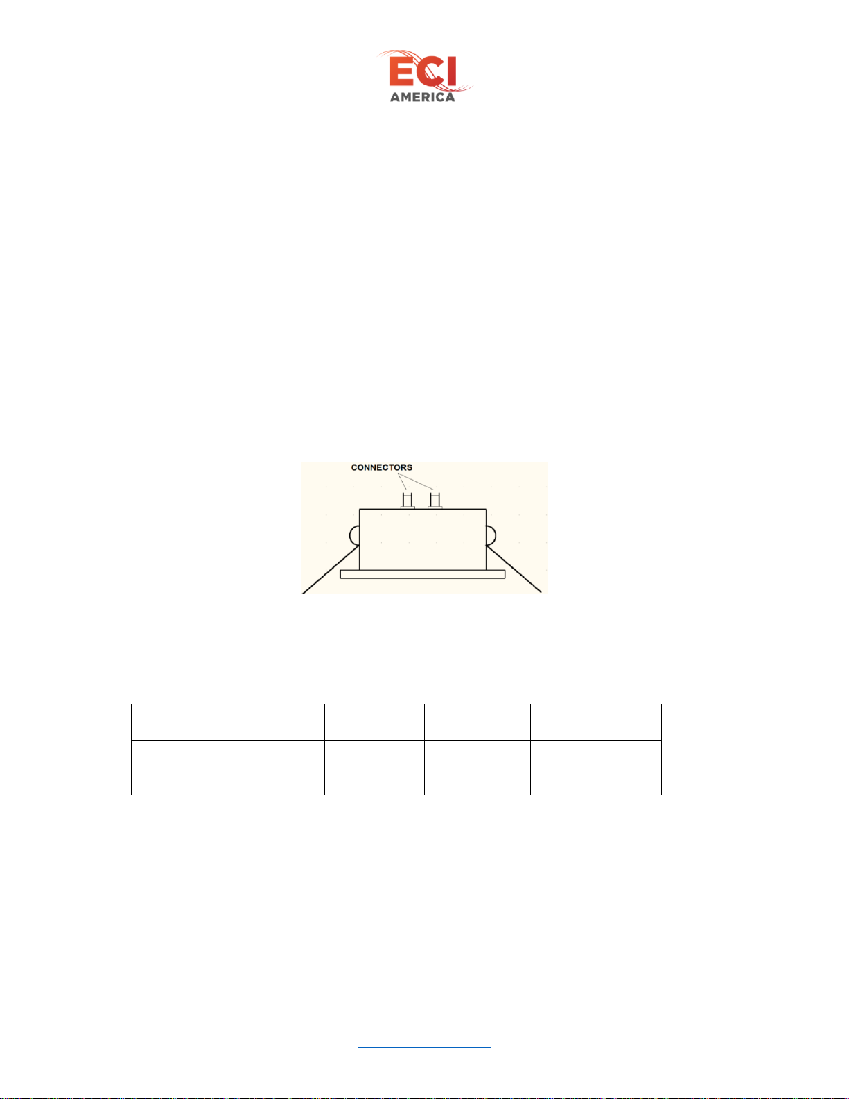
Each downlight is equipped with 2 connectors (located on the top of the can) for chaining up to 12 lights
together. The 2 connectors are interchangeable so it does not matter which cable is connected to it. See
Figure 1 - Downlight Connectors. Each downlight has 2 spring loaded clips that hold the light tight to the
ceiling panel.
Figure 1 - Downlight Connectors
6.1.1 ECO Downlight Specifications
Operating voltage 24VDC
5000K
4000K
3000K
# of LEDs
1
1
1
Color Temp
5000K
4000K
3000K
Power Consumption
8W
8W
8W
CRI
80 +/-5
85 +/-5
85 +/-5
6.2 CabLite ECO
The CabLite ECO is our very basic lighting system consisting of the following:
•1 to 12 downlights
•24VDC power supply (mounted in gang box)
•One 8’ cable for connecting first downlight
•One 4’ cable for each additional downlight
•Gang box and cover
Cablite ECO Installation Manual Rev 4.0
Electronic Controls, Inc.
7073 North Atlantic Ave. Cape Canaveral, FL 32920
800-633-9788
www.eciamerica.com P a g e | 7
•Installation Manual
6.3 CabLite ECO with Dimming Option
•1 to 12 downlights
•Dimmer board (factory wired and mounted in gang box)
•24VDC power supply (factory wired and mounted in gang box)
•One 8’ cable for connecting first downlight (factory wired and located in gang box)
•One 4’ cable for each additional downlight
•Gang box and cover
•Installation Manual
This option allows for setting a desired brightness level for the cab by adjusting potentiometer located on
the Dimming board. There is also a connection on the board for an optional remote potentiometer
(customer provided) so brightness levels can be manually adjusted without having to access the car top.
The AC voltage input of the power supply (Brown = LINE, Blue = NEU) is left free for the customer to
decide how to connect. Figure 8 - CabLite ECO with Dimming Wiring shows wire nuts.
The 24VDC power supply output is prewired at the factory to the Dimmer Board. The Dimmer board has
a 12” cable prewired to the LIGHTING Output of the Dimmer board. It has a two pin connector for easy
connection to the 8’ cable of the first downlight.
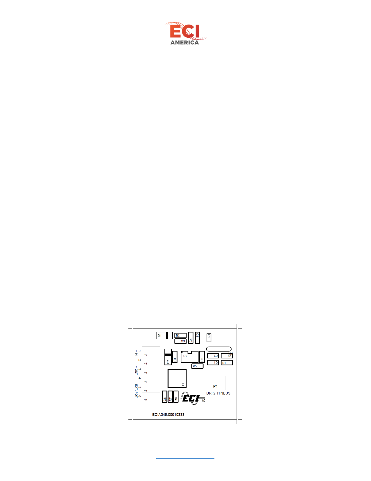
6.3.1 Dimmer Board
The Dimmer Board (Figure 2 - Dimmer Board) allows for adjusting light level using the BROGHTNESS
potentiometer located on the board. The board comes factory prewired for easy installation.
6.3.1.1 Dimmer Board Connections
•Pin 1 is +24VDC output from supply (RED wire)
•Pin 2 is -24VDC output from supply (BLACK wire)
•Pin 3 is “+” LED output
•Pin 4 is “-“ LED output
•Pins 5 & 6 are for an optional external potentiometer (Customer provided) for setting brightness
level in place of using on board potentiometer.

Cablite ECO Installation Manual Rev 4.0
Electronic Controls, Inc.
7073 North Atlantic Ave. Cape Canaveral, FL 32920
800-633-9788
www.eciamerica.com P a g e | 8
Figure 2 - Dimmer Board
6.4 CabLite ECO with Dimming and Emergency Lighting Option
This option allows for brightness control and emergency lighting. Included with this option:
•1 to 12 downlights
•Emergency Light board (factory wired and mounted in gang box)
•24VDC power supply (factory wired and mounted in gang box)
•12 Volt Battery (Factory wired w/ + side disconnected)
•Two 8’ cables for connecting first downlights (factory wired and located in gang box)
•One 4’ cable for each additional downlight
•Gang box and cover
•Installation Manual
This option allows for brightness settings and emergency lighting (2 downlights). In addition, there is a
standby mode that will turn off all downlights when cab is not in use. This is achieved with a key switch
connected to the STBY input pins 9 & 10.
6.4.1 CabLite ECO Emergency Board Connections
Refer to Figure 3 - CabLite ECO Emergency Board
•Pin 1 (IN +) is +24VDC input power (RED Wire)
•Pin 2 (IN-) is -24VDC input (BLACK Wire)
•Pin 3 (OUT+) is + output for general power (AC present) Downlight String (RED Wire)
•Pin 4 (OUT-) is –output for general power downlight string (BLACK Wire)
•Pin 5 & 6 is for external potentiometer (customer provided) for brightness adjustment
•Pin 7 (EM+) is + output for EMERGENCY downlight string (2 downlights) (RED wire)
•Pin 8 (EM-) is –output for EMERGENCY downlight string (2 downlights) (Black wire)
•Pin 9 & 10 (STBY) –is for external key switch that turns all downlights off when pin 9 & 10 are
closed. When closed EMERGENCY downlights will light only if AC power is lost.
•Pin 11 (BAT+) + side connection to battery
•Pin 12 (BAT-) –side connection to battery
•Pin 13 is FAULT relay common
•Pin 14 is Normally Closed contact of fault relay: Contacts open (between Common pin 13) when
there is a Battery Fault
•Pin 15 is the Normally open contact of the fault relay: Contacts close (between Common pin 13)
when there is a battery fault.

Cablite ECO Installation Manual Rev 4.0
Electronic Controls, Inc.
7073 North Atlantic Ave. Cape Canaveral, FL 32920
800-633-9788
www.eciamerica.com P a g e | 9
Figure 3 - CabLite ECO Emergency Board
6.4.2 CabLite Emergency Board LEDs
•CHARGE –the charge LED blinks when the battery is charging and remains solid when battery
is fully charged.
•FAULT –The fault LED lights when there is a problem with the battery. Wrong voltage or not
charging.
7Installation
Be sure all power is turned off before starting installation.
Locate the positions where you want each downlight and drill the ceiling panels according to the
specifications for your downlight listed in sections 7.1 and 7.2.
Be sure there is a minimum 1” clearance between the top of the downlight can and the cab
top to accommodate the connectors. See Figure 6 - Installation example

Cablite ECO Installation Manual Rev 4.0
Electronic Controls, Inc.
7073 North Atlantic Ave. Cape Canaveral, FL 32920
800-633-9788
www.eciamerica.com P a g e | 10
7.1 Flat Bezel Downlight Dimensions
Figure 4 - Flat Bezel Downlight Dimensions
7.2 Raised Bezel Downlight Dimensions
Figure 5 - Raised Bezel Downlight Dimensions
Figure 6 - Installation example
Cablite ECO Installation Manual Rev 4.0
Electronic Controls, Inc.
7073 North Atlantic Ave. Cape Canaveral, FL 32920
800-633-9788
www.eciamerica.com P a g e | 11
7.3 CabLite ECO Wiring Diagram
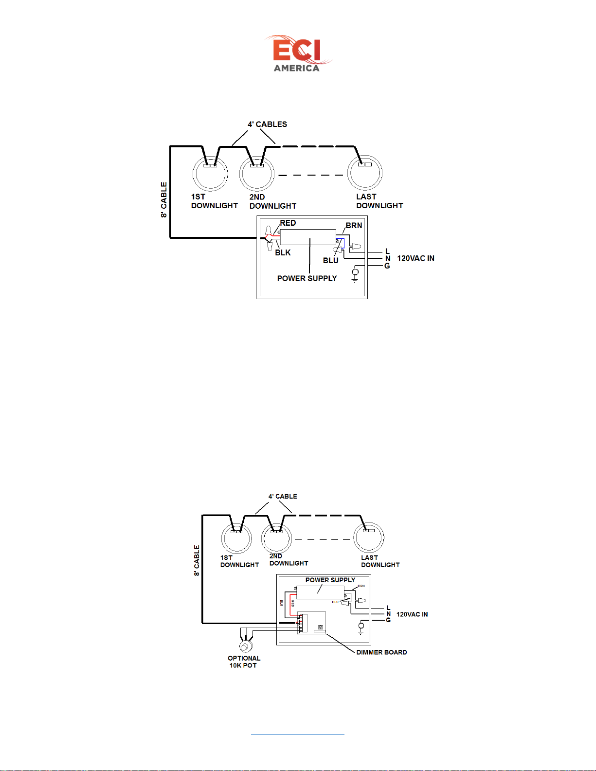
Figure 7 - CabLite ECO Wiring Diagram
Wire power supply as shown in Figure 7 - CabLite ECO Wiring Diagram.
•AC IN line –Brown wire on power supply
•AC IN neutral –Blue wire on power supply
•DC OUT + is RED wire of 8’ cable
•DC OUT –is BLACK wire of 8’ cable
Route the 8’ cable to the first downlight and connect remaining downlights with 4’ cables. The two
connectors on the downlights are interchangeable so cable connection does not matter.
Once wiring is complete and cover is on power supply box, apply power to lighting system. Check that
all downlights are lit.
7.4 CabLite ECO w/ Dimming Wiring Diagram
Figure 8 - CabLite ECO with Dimming Wiring
Cablite ECO Installation Manual Rev 4.0
Electronic Controls, Inc.
7073 North Atlantic Ave. Cape Canaveral, FL 32920
800-633-9788
www.eciamerica.com P a g e | 12
As previously mentioned the CabLite system power supply and dimming board are pre-wired from the
factory. Route AC power through one of the punch outs of the gang box and secure cable to box with
appropriate hardware. Connect AC in as shown in Figure 8 - CabLite ECO with Dimming Wiring.
•AC IN line –Brown wire on power supply
•AC IN neutral –Blue wire on power supply
Route the 8’ cable through another punch out of the gang box and secure to box using proper hardware.
Connect the 8’ cable to the first downlight and the remaining downlights with the 4’ cables. The two
connectors on the downlights are interchangeable so cable connection does not matter.
Apply power to lighting system and adjust brightness using the potentiometer on the Diming board. (See
Figure 2 - Dimmer Board).
When complete install cover to power unit.
7.5 CabLite ECO w/ Dimming & Emergency Wiring
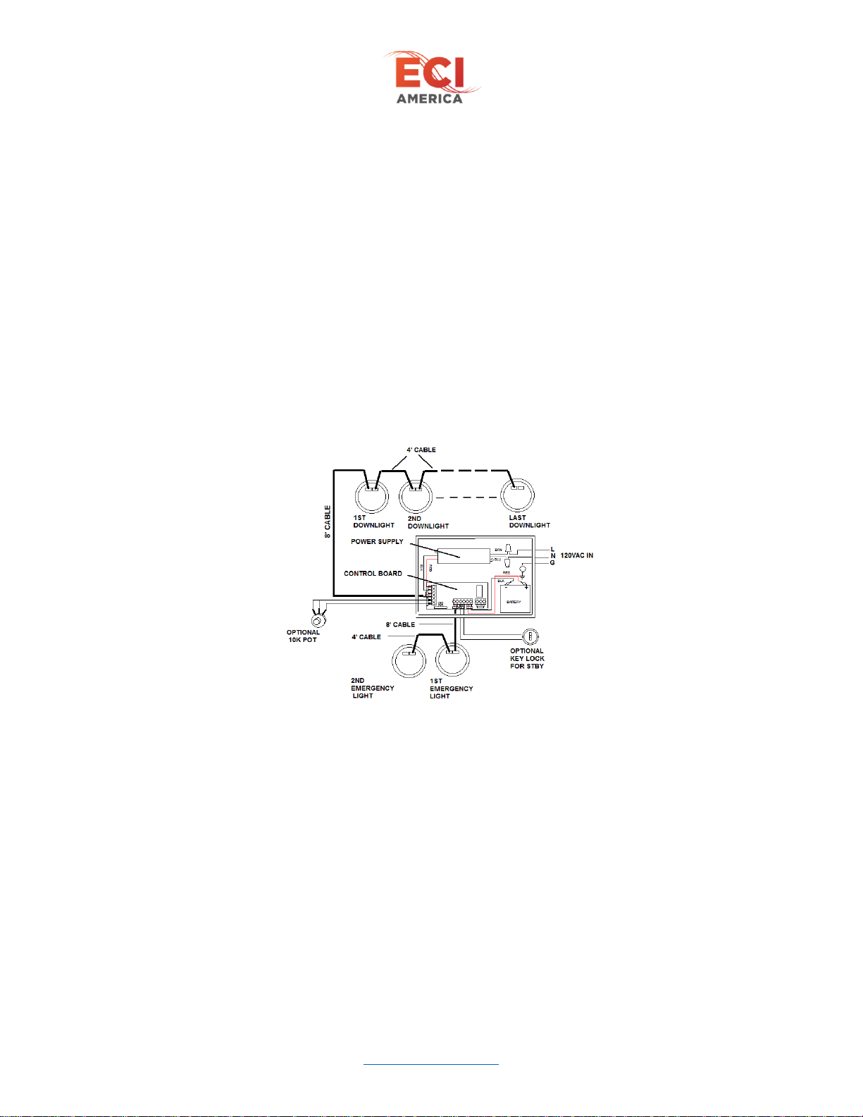
Figure 9 - CabLite ECO w/ Dimming & Emergency Wiring
As previously mentioned the CabLite system power supply and dimming board are pre-wired from the
factory. The BATTERY negative terminal is prewired to the control board and the positive terminal is
left disconnected. Route AC power through one of the punch outs of the gang box and secure cable to
box with appropriate hardware. Connect AC in as shown in Figure 9 - CabLite ECO w/ Dimming &
Emergency Wiring.
•AC IN line –Brown wire on power supply
•AC IN neutral –Blue wire on power supply
Route the 8’ cable through another punch out of the gang box and secure to box using proper hardware.
Connect the 8’ cable to the first downlight and the remaining downlights with the 4’ cables. The two
connectors on the downlights are interchangeable so cable connection does not matter.

Cablite ECO Installation Manual Rev 4.0
Electronic Controls, Inc.
7073 North Atlantic Ave. Cape Canaveral, FL 32920
800-633-9788
www.eciamerica.com P a g e | 13
The EMERGENCY lights are connected through a second 8’ cable as shown in Figure 9. There should
be two and only two downlights connected for emergency. Connecting more than two will shorten the
emergency lighting time.
With all downlights connected, remove the plastic cover from the POS terminal of the battery and connect
RED wire from control board to battery POS terminal. The EMERGENCY downlights should light at
this time.
Apply AC power to CabLite system. All downlights should light. Adjust the brightness of the
downlights through the potentiometer on the control board. See Figure 3 - CabLite ECO Emergency
Board.
When complete replace cover.
Allow 24 hours for battery to fully charge

Cablite ECO Installation Manual Rev 4.0
Electronic Controls, Inc.
7073 North Atlantic Ave. Cape Canaveral, FL 32920
800-633-9788
www.eciamerica.com P a g e | 14
8Trouble Shooting
8.1 One Light Does Not Turn On
1) Swap downlight with another light in string.
a) If light still does not operate replace downlight.
b) If downlight lights, then check original connection to downlight.
i) Replaced cable if necessary
8.2 Lights Do Not turn On (CabLite ECO)
1) Check connection between power supply and first downlight.
2) Check for 24VDC at power supply output
a) If no 24VDC check for 120VAc at power supply input
i) If 120VAC present replace power supply.
b) If 24VDC present replace 8’ cable
8.3 Lights Do Not Turn On (CabLite ECO w/ Dimming and Dimming/Emergency)
1) Check connection between control board and first downlight.
2) Using DVM measure +OUT- for 24VDC.
a) If no 24VDC check for 24VDC at +IN-
i) If no 24VDC at +IN- then check for 120VAC at power supply input
ii) If 120VAC present replace power supply.
b) If 24VDC present at +IN- then replace Control board.
3) If 24VDC present at +OUT- then check continuity of 8’ cable and replace if necessary.
8.4 No Emergency Lights with AC loss (Emergency light option)
1) Check connection between control board and first emergency downlight in string.
a) Check continuity of 8’ cable and replace if necessary.
2) With no AC power applied and battery connected, check for 12VDC at +EM- output of control board
a) If no 12VDC, check connections between battery and control board.
b) Check Battery voltage for 12VDC and replace battery in necessary.
3) Check FAULT LED on control board (AC power required).
a) If lit replace battery
8.5 Designated Emergency Lights Do Not Light with AC Power (Emergency light
option)
1) Check connection between control board and first downlight.
2) Check for 24VDC at +EM- output.
a) If 24VDC present replace 8’ cable
b) If no 24VDC replace control board.
This manual suits for next models
3
Table of contents
Popular Light Fixture manuals by other brands

Sunsystem
Sunsystem Pro Sun 2 1000W 208-240 V Installation and operating instructions

Lightolier
Lightolier PRISTINE T2 installation instructions

Chauvet
Chauvet LED-PAR200B user manual

HUBBELL LIGHTING
HUBBELL LIGHTING COMPASS CU2FO manual

Philips
Philips Pacific II TCW097 Specifications

Future light
Future light PHW-700 Pro-Head-Wash user manual

Lightolier
Lightolier Md.Coffer MDCGWSVA2SB4SB specification

JONATHAN Y
JONATHAN Y JYL7501A manual

Waldmann
Waldmann SLIM LED LIQ Series Instructions for use

Chauvet
Chauvet Q-Spot 160-LED user manual

STEINEL PROFESSIONAL
STEINEL PROFESSIONAL SensorLight L 680 LED Information

Anslut
Anslut 422-937 User instructions


