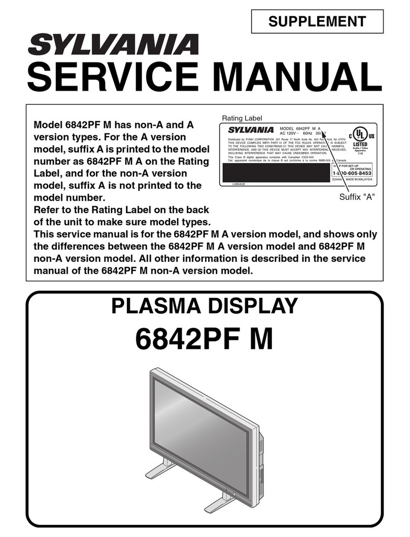
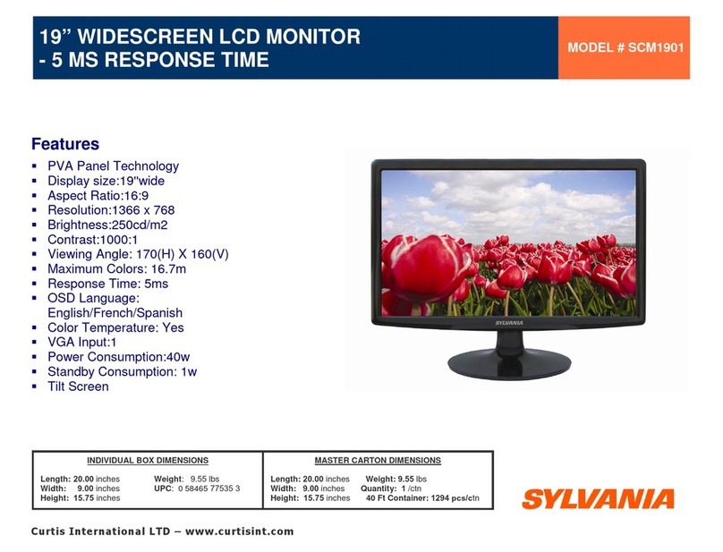
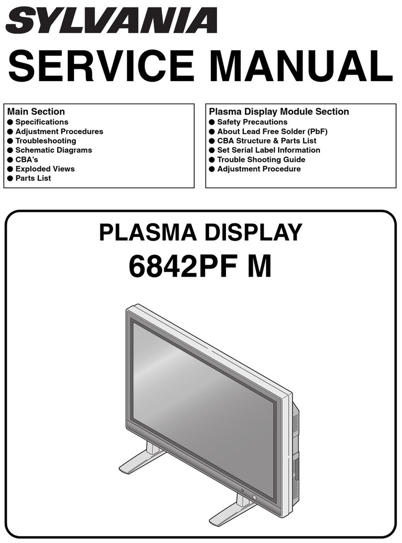
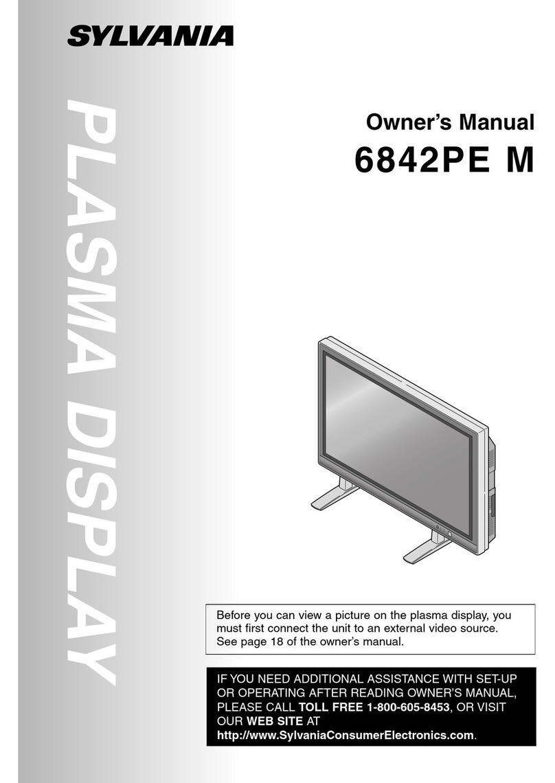
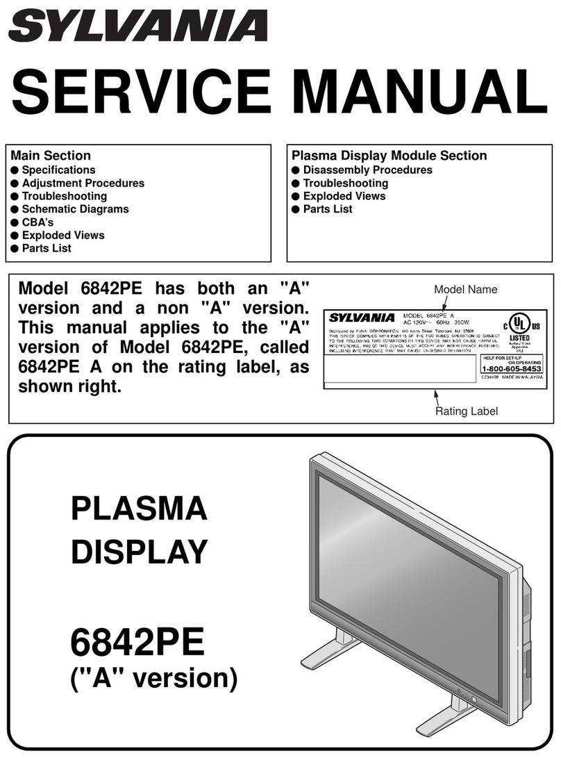
Sylvania 6842PE M User manual

PLASMA
DISPLAY
6842PE
SERVICE MANUAL
This service manual shows only the differences between
the model 6842PE and the original model F42PDME.
All other information is described in the service manual
of the model F42PDME.
SUPPLEMENT

IMPORTANT SAFETY NOTICE
Proper service and repair is important to the safe, reliable operation of all
Funai Equipment. The service procedures recommended by Funai and de-
scribed in this service manual are effective methods of performing service
operations. Some of these service special tools should be used when and
as recommended.
It is important to note that this service manual contains various CAUTIONS
and NOTICES which should be carefully read in order to minimize the risk of
personal injury to service personnel. The possibility exists that improper
service methods may damage the equipment. It also is important to under-
stand that these CAUTIONS and NOTICES ARE NOT EXHAUSTIVE. Funai
could not possibly know, evaluate and advice the service trade of all con-
ceivable ways in which service might be done or of the possible hazardous
consequences of each way. Consequently, Funai has not undertaken any
such broad evaluation. Accordingly, a servicer who uses a service proce-
dure or tool which is not recommended by Funai must first use all precau-
tions thoroughly so that neither his safety nor the safe operation of the
equipment will be jeopardized by the service method selected.
TABLE OF CONTENTS
Specifications............................................................................................... 1-1-1
Basic Setup and Operating Guide ............................................................... 1-2-1
Cabinet Disassembly Instructions................................................................ 1-3-1
Electrical Adjustment Instructions................................................................ 1-4-1
Block Diagrams............................................................................................ 1-5-1
Schematic Diagrams / CBA’s and Test Points............................................. 1-6-1
Wiring Diagram............................................................................................ 1-7-1
Lead Identifications...................................................................................... 1-8-1
Cabinet Exploded Views.............................................................................. 1-9-1
Packing Exploded Views.............................................................................. 1-9-3
Mechanical Parts List................................................................................. 1-10-1
Electrical Parts List .................................................................................... 1-11-1

1-1-1 L0601SP
SPECIFICATIONS
Note:
Nominal specifications represent the design specifications. All units should be able to approximate these. Some
will exceed and some may drop slightly below these specifications. Limit specifications represent the absolute
worst condition that still might be considered acceptable. In no case should a unit fail to meet limit specifications.
Description Condition
Display Features
Screen Size 920.1 (W) x 518.4 (H) mm, 42 in. Wide VGA panel
Pixel Resolution 852 (H) x 480 (V)
Output Colors 16.7 million
Screen Aspect Ratio 16:9
Contrast Ratio 1000:1
Brightness 470 cd/m2(PEAK)
Comb Filter Type 3-Dimensional Y/C Separation
Available Input Format 720p/1080i/480p/480i (720p/1080i/480p: Component 2 only)
Audio Features
Sound Output 5W + 5W, 10% THD
Speaker 2.8 in x 1.6 in Oval Type x 2
Audio IN 0.5Vrms
Connectors
Component AV Input (1) SD component video/Y, Cb, Cr, (RCA x 3) - rear
audio L/R (RCA x 2) - rear
Y: 1.0Vp-p (75 Ohm), Cb/Cr: 0.7Vp-p (75 Ohm)
Component AV Input (2) HD component video/Y, Pb, Pr, (RCA x 3) - rear
audio L/R (RCA x 2) - rear
Y: 1.0Vp-p (75 Ohm), Pb/Pr: 0.7Vp-p (75 Ohm)
Composite AV Input (1)
S-Video (1) Composite video (RCA x 1) - rear, 1.0Vp-p (75 Ohm)
S-Video (4 pin DIN) - rear
audio L/R (RCA x 2) - rear
Y: 1.0Vp-p (75 Ohm), C: 0.286Vp-p (75 Ohm)
Composite AV Input (2)
S-Video (2) Composite video (RCA x 1) - side, 1.0Vp-p (75 Ohm)
S-Video (4 pin DIN) - side
audio L/R (RCA x 2) - side
Y: 1.0Vp-p (75 Ohm), C: 0.286Vp-p (75 Ohm)
Analog Audio output audio L/R (RCA x 2) - rear
General
Power In 120V ±10%, 60Hz/AC
Power Consumption 350 W (standby-condition 0.8W)
Operation Temperature 41F - 104F (5°C - 40°C)
Humidity Under 80%
Dimension 1054 (W) x 660 (H) x 115 (D) mm
1054 (W) x 730 (H) x 330 (D) mm (Incl. Stand)
Weight 94.8 lbs (43 kg)

1-1-2 L0601SP
DIMENSIONS
330 600
70
71.6
660
518.4
1054
920.1
115
58 57

1-2-1 L0601IB
BASIC SETUP AND OPERATING GUIDE
1
POWER button: Turns the power ON or in
STANDBY.
2
ON indicator: Lights up when the power is
ON.
3
STANDBY indicator: Lights up when the
power is in the standby mode. Disappears
when the power is ON.
4
INPUT SELECT button: Selects input termi-
nals.
5
VOLUME (up) / (down) button:
Increases or decreases the volume.
6
AC IN terminal: Connect the supplied
power cable for a standard AC outlet.
7
AUDIO OUT: Output terminals for audio.
8AUDIO/VIDEO/S-VIDEO: Input terminals fo
r
an audio and video signal. You can select
either VIDEO or S-VIDEO.
9COMPONENT: Input terminals for a compo
-
nent signal. You can make a Y-Cb-Cr inter-
laced connection to component 1 or Y-Pb-P
r
progressive or interlaced connection to com
-
ponent 2.
M
AIN UNIT
VOLUME
INPUT SELECT
STANDBY
ON POWER
VOLUME
INPUTSELECT
STANDBY
ON POWER
1
2
3
4
Infrared Sensor
5
Input Terminals
Input Terminals
R L Y Cb Cr
RLYPbPr
AUDIO
COMPONENT 1
COMPONENT 2
VIDEO1AUDIO S-VIDEO1
LR
R
L
AUDIO OUT
AC IN
AUDIO
VIDEO2
S-VIDEO2
R
L
6 7 8 9
8
F
ront Rear

1-2-2 L0601IB
R
EMOTE CONTROL
1POWER button: Turns the main power ON
or in STANDBY.
2VOL (up) / (down) button: Increases or
decreases the volume.
3MUTE button: Turns the audio off or on.
4SCREEN MODE button: Selects aspect
ratios available for the screen.
5STILL button: Pauses the image shown on
the screen.
6INPUT SELECT button: Selects input termi-
nals.
7DISPLAY button: Displays the name of the
selected input terminal on the screen.
8SLEEP button: Sets the sleep timer.
9MENU button: Accesses the setup menu,
allowing you to access various settings.
10
PREVIOUS button: Moves up one level in
the setup menu.
11
(up) / (down) button: Selects the vari-
ous modes in the setup menu.
(left) / (right) button: Selects and
adjusts levels for the various settings.
(enter) button: Also used as the enter
button.
POWER
INPUT SELECT
DISPLAY
MENU
PREVIOUS
SLEEP
VOL
MUTE
SCREEN MODE
STILL
1
2
3
4
5
6
7
8
9
10
11

1-3-1 L0601DC
CABINET DISASSEMBLY INSTRUCTIONS
1. Disassembly Flowchart
This flowchart indicates the disassembly steps for the
cabinet parts, and the CBA in order to gain access to
item(s) to be serviced. When reassembling, follow the
steps in reverse order. Bend, route and dress the
cables as they were.
2. Disassembly Method
↓↓ ↓ ↓ ↓
(1) (2) (3) (4) (5)
Note:
(1) Order of steps in procedure. When reassembling,
follow the steps in reverse order. These numbers
are also used as the Identification (location) No. of
parts in figures.
(2) Parts to be removed or installed.
(3) Fig. No. showing procedure of part location
(4) Identification of part to be removed, unhooked, un-
locked, released, unplugged, unclamped, or des-
oldered.
S=Screw, P=Spring, L=Locking Tab, CN=Con-
nector, *=Unhook, Unlock, Release, Unplug, or
Desolder
2(S-2) = two Screws (S-2)
(5) Refer to the following "Reference Notes in the
Table.
Step/
Loc.
No. Part Removal
Fig.
No Remove/*unlock/release/
unplug/unclamp/desolder Note
1 Rear Cabinet 1 26(S-1) 1
2Front Cabinet
Assembly 2 14(S-2) 2
3 Filter Holder(L) 2 6(S-3) 3
4 Filter Holder(S) 2 6(S-4) 4
5 Optical Filter 2 ---------- -
6 Decoration Panel 3 14(S-3) 5
7 Front Cabinet 3 ---------- -
8 Jack Bracket 4 4(S-6) 6
9 Jack Holder 4 2(S-7), (S-8) 7
10 Jack CBA 4
10 2(S-9), *CN751 8
[6] Decoration
Panel
[7] Front
Cabinet
[8] Jack Bracket
[9] Jack Holder
[10] Jack CBA [15] Filter CBA[16] PCB Holder
[24] Chassis
Bracket
[25] Panel
Spacer
[26] Jack Cover
[27] Plasma
Display Module
[28] Panel
Holder Assembly
[17] Stand Cover
[11] PCB
Shield Plate [12] Shield Box
[13] Digital CBA [14] Analog CB
A
[18] Stand
[19] Stand Base
[20] Rubber
Foot
[22] Speaker
Cover
[21] Speaker
Holder
[23] Speaker
[1] Rear Cabinet
[2] Front Cabinet
Assembly [3] Filter
Holder(L)
[4] Filter
Holder(S)
[5] Optical
Filter
11 PCB Shield Plate 4 18(S-10), CLN8 9
12 Shield Box 4 14(S-11) 10
13 Digital CBA 5
9
*CN1701, *CN1702,
*CN1703, *CN1704,
*CN1706, *CN1707,
4(S-12), 3(S-13)
11
14 Analog CBA 5
10
*CN201, *CN203, *CN204,
*CN501, *CN502, *CN701,
*CN702, *CN801, *CN802,
4(S-14), 2(S-15)
12
15 Filter CBA 5
11 *CN801, Inlet Holder, AC
Cord, (S-16A), (S-17) 13
16 PCB Holder 5 4(S-18) 14
17 Stand Cover 6 4(S-19), 6(S-19B) 15
18 Stand 6 4(S-20) 16
19 Stand Base 6 8(S-21) 17
20 Rubber Foot 6 ----------
21 Speaker Holder 7 8(S-22) 18
22 Speaker Cover 7 2(S-23) 19
23 Speaker 7 8(S-24) 20
24 Chassis Bracket 7 8(S-25) 21
25 Panel Spacer 7 8(S-26) 22
26 Jack Cover 7 2(S-28) 23
27 Plasma Display
Module 8 ---------- -
28 Panel Holder
Assembly 8 ---------- -
Step/
Loc.
No. Part Removal
Fig.
No Remove/*unlock/release/
unplug/unclamp/desolder Note
1-3-2 L0601DC
Reference Notes in the Table
Caution:
Refer to "General Caution of Plasma Display" and
"PDP Module Handling" of "IMPORTANT SAFETY
PRECAUTIONS" section not to injure and/or break the
Plasma Display Module.
1. Removal of the Rear Cabinet. Remove screws
26(S-1).
2. Removal of the Front Cabinet Assembly. Remove
screws 14(S-2).
3. Removal of the Filter Holder(L). Remove screws
6(S-3).
4. Removal of the Filter Holder(S). Remove screws
6(S-4).
5. Removal of the Decoration Panel. Remove screws
14(S-3).
6. Removal of the Jack Bracket. Remove screws 4(S-
6).
7. Removal of the Jack Holder. Remove screws 2(S-
7) and (S-8).
8. Removal of the Jack CBA. Remove screws 2(S-9)
and disconnect connector *CN751.
9. Removal of the PCB Shield Plate. Remove screws
18(S-10) and wire assembly CLN8.
10.Removal of the Shield Box. Remove screws 14(S-
11).
11.Removal of the Digital CBA. Disconnect connec-
tors *CN1701, *CN1702, *CN1703, *CN1706, and
*CN1707, and remove screws 4(S-12) and 3(S-
13).
12.Removal of the Analog CBA. Disconnect connec-
tors *CN201, *CN203, *CN204, *CN501, *CN502,
*CN701, *CN702, *CN801, and *CN802, and
remove screws 4(S-14) and 2(S-15).
13.Removal of the Filter CBA. Disconnect connector
*CN801, and remove the Inlet Holder and AC Cord,
then remove screws (S-16A), and (S-17).
14.Removal of the PCB Holder. Remove screws 4(S-
18).
15.Removal of the Stand Cover. Remove screws 4(S-
19) and 6(S-19B).
16.Removal of the Stand. Remove screws 4(S-20).
17.Removal of the Stand Base. Remove screws 8(S-
21).
18.Removal of the Speaker Holder. Remove screws
8(S-22).
19.Removal of the Speaker Cover. Remove screws
2(S-23).
20.Removal of the Speaker. Remove screws 8(S-24).
21.Removal of the Chassis Bracket. Remove screws
8(S-25).
22.Removal of the Panel Spacer. Remove screws
8(S-26) and 8(S-27).
23.Removal of the Jack Cover. Remove screws 2(S-
28).

1-3-3 L0601DC
Fig. 1
[1] Rear Cabinet
(S-1)
(S-1)
(S-1)
(S-1)
(S-1)
(S-1)
Fig. 2
[2] Front Cabinet Assembly
[3] Filter Holder(L)
[3] Filter Holder(L)
[4] Filter Holder(S)
[5] Optical Filter
[4] Filter
Holder(S) (S-2)
(S-2)
(S-2)
(S-2)
(S-4)
(S-3)
(S-3)
(S-3)
(S-4)
(S-4)
(S-4)

1-3-4 L0601DC
Fig. 3
[6] Decoration Panel
[7] Front Cabinet
(S-5)
(S-5)
(S-5)
(S-5)
Fig. 4
[8] Jack Bracket
[9] Jack Holder
[10] Jack CBA
[11] PCB
Shield Plate
[12] Shield Box
[12] Shield Box
(S-6)
(S-6)
(S-7
)
(S-7
)
(S-9)
(S-10)
(S-10) CLN8
(S-10)
(S-10)
(S-11)
(S-11)
(S-11)
(S-11)
(S-11) (S-10)
(S-8
)
(S-10)

1-3-5 L0601DC
[13] Digital CBA
[16] PCB Holder
[14] Analog CBA
[15] Filter
CBA
(S-12)
(S-12) (S-14)
(S-14)
(S-17)
(S-16A)
(S-13)
(S-15)
(S-18)
(S-18)
(S-18)
Inlet Holder
AC Cord Fig. 5
Connectors
(to AC Inlet)
[17] Stand Cover
[17] Stand Cover
[18] Stand
[18] Stand
[19] Stand Base
[19] Stand Base
[20] Rubber Foot
[20] Rubber Foot
(S-19)
(S-20)
(S-19B)
(S-19B)
(S-19B)
(S-19B)
(S-20)
(S-21)
(S-21)
(S-21)
(S-21)
(S-20)
(S-20)
(S-19)
Fig. 6

1-3-6 L0601DC
[24] Chassis
Bracket
[24] Chassis Bracket
[25] Panel Spacer
[26] Jack Cover
[21] Speaker
Holder
[21] Speaker Holder
[22] Speaker
Cover
[22] Speaker Cover
[23] Speaker
[23] Speaker
(S-25)
(S-26)
(S-26)
(S-26)
(S-23)
(S-23)
(S-24)
(S-24)
(S-26)
(S-26)
(S-26)
(S-27)
(S-28)
(S-27)
(S-27)
(S-27)
(S-27)
(S-25)
(S-25)
(S-22
)
(S-22)
(S-22)
(S-22)
(S-25)
Fig. 7
[28] Panel Holder Assembly
[27] Plasma Display Module
Fig. 8

1-3-7 L0601DC
Plasma Display Cable Wiring Diagram
Fig. 9
Cables on the Digital CBA
Clamper CN1707
CN1704
CN1706
ClamperSwtich CBA CN1902 Digital CBA
CN203
CN201
CN701
CN1703
CN1702
CN1701
to P31
Ferrite core (FC3)
Ferrite
core (FC1)
Ferrite
core (FC6)
Clamper
Fig. 10
Cables on the Analog CBA
Clamper Clamper
Clamper
ClamperSwtich CBA
Jack CBA
Wrap the
wires twice
Ferrite
core (FC2)
CN801
CN1901
CN751 CN802 CN502
CN702
CN203
CN201
CN701
CN1703
CN1702
CN1701
Speaker Analog CBA Speaker
CN204
Ferrite
core (FC1)
Clamper
Clamper
CN501

1-3-8 L0601DC
Fig. 11
Cables on the Filter CBA
Clamper
Filter CBA
Earth
Clamper Clamper
CN801

1-4-1 L0601EA
ELECTRICAL ADJUSTMENT INSTRUCTIONS
General Note:
"CBA" is abbreviation for "Circuit Board Assem-
bly."
NOTE:
Electrical adjustments are required after replacing
circuit components and certain mechanical parts.
It is important to perform these adjustments only
after all repairs and replacements have been com-
pleted.
Also, do not attempt these adjustments unless the
proper equipment is available.
Test Equipment Required
1. NTSC Pattern Generator (Color Bar W/White Win-
dow, Red Color, Gray Scale)
2. Plastic Tip Driver
3. Remote control unit: Part No. N0105UD, N0108UD,
N0127UD or N0132UD
4. Color Analyzer
How to make service remote control
unit:
1. Prepare normal remote control unit. (Part No.
N0105UD, N0108UD, N0127UD or N0132UD) Re-
move 3 Screws from the back lid. (Fig. 1-1)
2. Add J1 (Jumper Wire) to the remote control CBA.
(Fig. 1-2)
How to set up the service mode:
Service mode:
1. Toturnthepoweron,press"POWER" button on the
normal remote control unit or the unit.
2. Use the service remote control unit.
3. Press "SLEEP" button on the service remote con-
trol unit. Fig. 2 appears on the screen.
4. Confirm the following
a. Version of main micro
computer --- PZ1_US_L_1.29 (or 1.31)
b. Version of sub micro computer --- K746_015
c. Memory size --- 32
d. FLASH DATA Check-Sum (press "0" button on
the service remote control unit) --- D968h (or
CB48h)
Initial setting:
1. Toturnthepoweron,press"POWER" button on the
normal remote control unit or the unit.
2. Enter the service mode.
3. To reset to factory setting, press "DISPLAY" but-
ton on the service remote control unit.
- "INITIALIZE" (red) appears on the screen as
shown in Fig. 3.
- After few seconds (completion initialization), col-
or of "INITIALIZE" will change green.
SCREW
REMOTE CONTROL UNIT Fig. 1-1
J 1
Fig. 1-2
REMOTE CONTROL CBA
MAIN UCOM Ver.
SUB UCOM Ver.
MEMORY SIZE
CHKSUM
: PZ1_US_L_1.29 (or 1.31)
: K746_015
: 32
: D968h (or CB48h)
Fig.
2
MAIN UCOM Ver.
SUB UCOM Ver.
MEMORY SIZE
CHKSUM
: ********
: ********
: 32
: ****
INITIALIZE
Fig.
3

1-4-2 L0601EA
1. Auto Calibration (Black & White)
1. Operate the unit more than 20 minutes.
2. Input black raster signal fromonly Component AVIn-
put (2) video/Y jack (green). Do not input any signal
to Component AV Input (2) video/Pb or Pr jack.
3. Enter the service mode.
4. To enter the Auto Calibration (Black) adjustment
mode, press "2" button on the service remote con-
trol unit. If no signal, "No signal" appears on the
screen.
5. To start auto adjustment, press "CH o" button on
the service remote control unit.
6. Input white raster signal (100% or 110%) from only
Component AV Input (2) video/Y jack(green).Do not
input any signal to Component AV Input (2) video/Pb
or Pr jack.
7. To enter the Auto Calibration (White) adjustment
mode, press "3" button on the service remote con-
trol unit. If no signal, "No signal" appears on the
screen.
8. To start auto adjustment, press "CH o" button on
the service remote control unit.
9. Upon completion, wait for at least 5 seconds.
10. UnplugACcordandplugitinAC outletagaintoreset
then enter the service mode again.
11. Confirm thatboththe"Black Calibration : Complete"
and "White Calibration : Complete" are displayed
on the screen as shown in Fig. 4. If "Yet" is dis-
played instead of "Complete", repeat above steps.
2. White Balance Adjustment
Purpose: To mix red, green and blue beams correctly
for pure white.
Symptom of Misadjustment: White becomes bluish
or reddish.
Notes:
- Use service remote control unit.
- This adjustment should be performed in both Com-
ponent 2 mode and Video 1 mode. Adjustment in
Component 2 mode should be performed after com-
pletion of ADC calibration adjustment.
1. Operate the unit more than 20 minutes.
2. Input the gray scale pattern signal (5 scales) from
Component AV Input (2) video/Y jack.
3. Set the color analyzer to the CHROMA mode and
after zero point calibration, for high light adjust-
ment, bring the optical receptor to the 2nd scale as
shown below.
4. Enter the Service mode.
MAIN UCOM Ver.
SUB UCOM Ver.
MEMORY SIZE
CHKSUM
: ********
: ********
: 32
: Push 0 key
Black Calibration : Complete
White Calibration : Complete
Fig. 4
Test
Point Adj.
Point Mode Input
Screen CH o/ p
buttons Video 1 &
Component 2
Gray scale
pattern signal
(5 scales)
M. EQ. Spec.
Pattern Generator,
Color analyzer See below
Figure
Color Analyzer
Fig. 5
Fig. 6
2nd gray scale

1-4-3 L0601EA
5. Enter the component adjustment mode, press
"VOL p" button once on the service remote control
unit.
6. Press "4" button on the service remote control unit
for Red adjustment. Press "6" button on the service
remote control unit for Blue adjustment.
7. In each color mode, press "CH o/ p"button to ad-
just the values of color.
8. Adjust Red and Blue color so that the temperature
becomes 9200°K-5MPCD (x: 288 / y: 288) ±3%.
9. For low light adjustment, bring the optical receptor
to the 4th scale as shown below.
10. Press "1" button on the service remote control unit
for Red adjustment. Press "3" button on the service
remote control unit for Blue adjustment.
11. In each color mode, press "CH o/ p"button to ad-
just the values of color.
12. Adjust Red and Blue color so that the temperature
becomes 9200°K-5MPCD (x: 288 / y: 288) ±3%.
13. Check adjustment value in high light adjustment
again. If adjustment value is not within specifica-
tion, repeat steps 2-8.
14. To enter the adjustment mode in the Composite
mode (Video 1 mode), press "VOL p" button once
on the service remote control unit.
15. Input the gray scale pattern signal (5 scales) from
Composite AV Input (1) video jack (Video 1).
16. Adjust in the same way above.
3. Sub-Brightness Adjustment
Purpose: To get proper brightness.
Symptom of Misadjustment: If Sub-Brightness is
incorrect, proper brightness cannot be obtained by
adjusting the Brightness Control.
Notes:
- IQW Setup level --- 7.5 IRE
- Use service remote control unit.
- This adjustment should be performed in both Com-
ponent 2 mode and Video 1 mode. Adjustment in
Component 2 mode should be performed after com-
pletion of ADC calibration adjustment.
1. Enter the Service mode. Then input IQW signal
from Component AV Input (2) video.
2. Press "VOL p" button on the service remote control
unit.
3. Press "7" on the service remote control unit.
4. Press "CH o/ p" buttons so that the bar is just vis-
ible. (Refer to Fig. 8.)
5. Input IQW signal from Composite AV Input (1) vid-
eo jack (Video 1).
6. To adjust in Composite mode (Video 1 mode), re-
peat steps 2 - 4.
7. Turn the power off and on again, using the main
power button on the TV unit.
Fig. 7
4th gray scale
Adj. Point Mode Input
CH o/ pbuttons Video 1 &
Component 2 IQW
M. EQ. Spec.
Pattern Generator See below
Figure
W
hite Black
Fig. 8
This ba
r
just
visible

1-5-1
BLOCK DIAGRAMS
System Control Block Diagram
L0601BLS
SWITCH CBA
DIGITAL CBA UNIT ANALOG CBA
IC205
(PDP MICROCONTROLLER)
IC1401
(DIAPLAY CONTROLLER)
IC201
(MEMORY)
+3.3V
+3.3V
+3.3V
SW1401
RESET CN203
CN1902
KEY
SWITCH
KEY-IN-POW
CN1703
CN1706
RXD
TXD
REMOTE
RESET
P-OFF-RQ
P-OFF-H
T17
Y12
V12
V11
Y11
W14
Y15
22KEY-IN1
33KEY-IN2
44KEY-IN3 CN204
RXD
REMOTE
CN1901
66
POWER-KEY
44REMOTE
22
POWER-LED
33
STANDBY-LED
KEY-IN1
V16
KEY-IN2
W16
KEY-IN3
Y16
VOLUME
V15
SW1908
RV1901
POWER
D1901
POWER
Q1401
VOLUME
CONTROL
Q271
Q272
Q207
Q206
BUFFER
REMOTE
SENSOR
+3.3V
+3.3V
D1902
STANDBY
15
39
TXD
POWER-SW
P-ON-H
4
56
14
RESET-181
38
P-OFF-RQ
54
P-OFF-H
A-OUT-MUTE
AUDIO-SW0
AUDIO-SW1
AUDIO-SW2
A-OUT-MUTE
AUDIO-SW0
AUDIO-SW1
AUDIO-SW2
SCL
SDA
SCL
SDA
55
31
30
29
28
48
47
VOLUME
P-ON-H
TO AUDIO
BLOCK DIAGRAM
TO VIDEO
BLOCK DIAGRAM
TO POWER SUPPLY
BLOCK DIAGRAM
TO
POWER SUPPLY
BLOCK DIAGRAM
6
5
IC1404
(MEMORY)
SCL
SDA
6
5
SCL
W13
W19
SDA
V13
RESET
PANEL-ON
RESET
Y14
PANEL-ON
TO DIGITAL
SIGNAL PROCESS 1
BLOCK DIAGRAM
SCL
SDA
SCL
SDA
12 KEY-IN-POW
8 RXD
7 TXD
10 REMOTE
4 RESET-181
14 P-OFF-RQ
15 P-OFF-H
16 VOLUME
12KEY-IN-POW
16TXD
17RXD
14REMOTE
20RESET-181
10P-OFF-RQ
9P-OFF-H
8VOLUME
I2C-READY
Y13
I2C-READY
PANEL-ON
TO DIGITAL
SIGNAL PROCESS 2
BLOCK DIAGRAM
A-MUTE
Q295
32
13
VOLUME-MUTE
11
VOLUME-MUTE

1-5-2 L0601BLV
Video Block Diagram
JK702
Q706 CN701
CN751 CN702
CN1701
IC1101 (VIDEO DECODER)
IC1301 (VIDEO DECODER)
IC1102 (SDRAM)
INPUT
SELECT
DIGITAL
SIGNAL
PROCESS
ADC
VIDEO1
IN
JACK CBA ANALOG CBA
DIGITAL CBA UNIT
VIDEO SIGNAL
1~4 6~9 11~19
JK752
VIDEO1
IN
VIDEO3-Y
IN
VIDEO3-Cb
IN
VIDEO3-Cr
IN
VIDEO4-Y
IN
VIDEO4-Pb
IN
VIDEO4-Pr
IN
JK701
S-VIDEO1 IN
JK751
S-VIDEO2 IN
3 4
2
1
YC
3 4
2
1
YC
88VIDEO1
10 6VIDEO1-Y
12 4VIDEO1-C
214VIDEO2
412VIDEO2-Y
610VIDEO2-C
55VIDEO2
77VIDEO2-Y
66VIDEO2-C
BUFFER
Q704
BUFFER
Q705
BUFFER
Q703
BUFFER
Q702
BUFFER
Q701
BUFFER
Q1702
JK1704
BUFFER
ADC
Q1704
BUFFER
Q1706
BUFFER
Q1701
BUFFER
Q1703
BUFFER
Q1705
BUFFER
137
100
101
103
104
106
143
139
135
145
141
149
153
151
159
INPUT
SELECT
FRAME DELAY
MEMORY CONTROL
ADC
ADC
PICTURE
/TONE
CONTROL
OUTPUT
FORMATTER
VUV[0]
VUV[0~7]
VY[0~7]
VUV[1]
VUV[2]
VUV[3]
VUV[4]
VUV[5]
VUV[6]
VUV[7]
95
67
65
64
62
61
59
58
56
97
98
TO DIGITAL
SIGNAL
PROCESS 2
BLOCK
DIAGRAM
TO DIGITAL
SIGNAL
PROCESS 1
BLOCK
DIAGRAM
TO SYSTEM
CONTROL
BLOCK
DIAGRAM
VY[0]
VY[1]
VY[2]
VY[3]
VY[4]
VY[5]
VY[6]
VY[7]
GRE[0]
RESET
GRE[0~7]
GGE[0~7]
GBE[0~7]
GRE[7]
33~40
21 22 24 25 27 28 30 31
43
44
51
35
VIDEO
DECODER
DATA
MULTIPLEXER
COLOR
SPACE
CONTROL
ITU-R656
DIGITAL
VIDEO
FORMATTER
OUTPUT
MULTIPLEXER
142
139
~
136
133
~
152
146
~
160
153
~
~
GGE[0]
GGE[7]
~
GBE[0]
GBE[7]
~
71
86
87
PVCLK
HD
VD
SERIAL
I/F
82
82
83
168 166
127
128
129
130
131
SERIAL
I/F
SDA
SCL
RESET
DCLK
DPEN
DHS
DFBK
DVS
ADRESS
DATA
R738
R746
WF12
WF6
WF13
R1774
R1776
R1778
R1773
R1775
R1777
WF7
WF8
WF9
WF11
WF10

1-5-3
Audio Block Diagram
L0601BLA
AUDIO1(L)
IN
Q707
CN1702 CN201
JACK CBA
ANALOG CBA
91AUDIO3(L)
82AUDIO3(R)
64AUDIO4(L)
JK702
AUDIO1(R)
IN
AUDIO3(L)
IN
JK1703
AUDIO3(R)
IN
AUDIO4(R)
IN
AUDIO4(L)
IN
AUDIO2(L)
IN
JK753
AUDIO2(R)
IN
JK754
55AUDIO4(R)
CN751 CN702
22AUDIO2(L)
11AUDIO2(R)
13
15
14
12
SW CTL
3
109 11
IC203
(INPUT SELECT)
13
15
14
12
SW CTL
3
109 11
IC202
(INPUT SELECT)
5
2 12
6
IC801
(AUDIO AMP)
7
VOLUME
CTL
1 SP-L
SP802
SPEAKER
L-CH
2 SP-GND
CN802
1 SP-R
SP801
SPEAKER
R-CH
2 SP-GND
CN801
Q801
AUDIO(L)
OUT
AUDIO(R)
OUT
JK703
Q708
Q711
Q712
Q709
Q710
AUDIO-SW0
AUDIO-SW1
AUDIO-SW2
Q205
Q204
Q203
AC-DET
VOLUME
AMP
AMP
AMP
AMP
+5V
A-OUT-MUTE
DIGTAL CBA UNIT
AUDIO SIGNAL
TO SYSTEM
CONTROL
BLOCK
DIAGRAM
TO SYSTEM
CONTROL
BLOCK DIAGRAM
WF14
TO POWER SUPPLY
BLOCK DIAGRAM
Q831
Other manuals for 6842PE M
4
Table of contents
Other Sylvania Monitor manuals

Sylvania
Sylvania 6842PE M User manual

Sylvania
Sylvania SCM1901 Instruction Manual

Sylvania
Sylvania SC171 User manual

Sylvania
Sylvania 6842PF M User manual

Sylvania
Sylvania 6842PE M User manual

Sylvania
Sylvania SRPD442 A User manual

Sylvania
Sylvania SC190 User manual

Sylvania
Sylvania SRPD442 A User manual

Sylvania
Sylvania SF150 User manual

Sylvania
Sylvania 6842PE M User manual