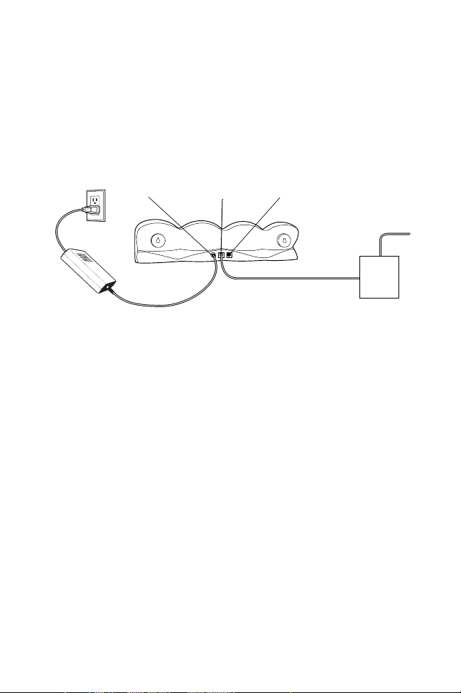
Symbol CRD1700-4000E User manual

CRD1700-4000E
Ethernet Cradle

CRD1700-4000E
Ethernet Cradle
2000 SYMBOL TECHNOLOGIES, INC. All rights reserved.
Symbol reserves the right to make changes to any product to improve reliabilit y,
function, or design.
Symbol does not assume any product liability arising out of, or in connection with, the
application or use of any product, circuit, or application described herein.
No license is granted, either expressly or by implication, estoppel, or otherwise under
any patent right or patent, covering or relating to any combination, system, apparatus,
machine, material, method, or process in which Symbol products might be used. An
implied license only exists for equipment, circuits, and subsystems contained in Symbol
products.
Symbol and the Symbol logo are registered trademarks of Symbol Technologies, Inc.
Other product names mentioned in this manual may be trademarks or registered
trademarks of their respective companies and are hereby acknowledged.
Symbol Technologies, Inc.
One Symbol Plaza
Holtsville, N.Y. 11742-1300
http://www.symbol.com
Patents
This product is covered by one or more of the following U.S. and foreign Patents:
U.S. Patent No. 4,460,120; 4,496,831; 4,593,186; 4,603,262; 4,607,156; 4,652,750;
4,673,805; 4,736,095; 4,758,717; 4,816,660; 4,845,350; 4,896,026; 4,897,532;
4,923,281; 4,933,538; 4,992,717; 5,015,833; 5,017,765; 5,021,641; 5,029,183;
5,047,617; 5,103,461; 5,113,445; 5,130,520; 5,140,144; 5,142,550; 5,149,950;
5,157,687; 5,168,148; 5,168,149; 5,180,904; 5,216,232; 5,229,591; 5,230,088;
5,235,167; 5,243,655; 5,247,162; 5,250,791; 5,250,792; 5,260,553; 5,262,627;
5,262,628; 5,266,787; 5,278,398; 5,280,162; 5,280,163; 5,280,164; 5,280,498;
5,304,786; 5,304,788; 5,306,900; 5,321,246; 5,324,924; 5,337,361; 5,367,151;
5,373,148; 5,378,882; 5,396,053; 5,396,055; 5,399,846; 5,408,081; 5,410,139;
5,410,140; 5,412,198; 5,418,812; 5,420,411; 5,436,440; 5,444,231; 5,449,891;
5,449,893; 5,468,949; 5,471,042; 5,478,998; 5,479,000; 5,479,002; 5,479,441;
5,504,322; 5,519,577; 5,528,621; 5,532,469; 5,543,610; 5,545,889; 5,552,592;
5,557,093; 5,578,810; 5,581,070; 5,589,679; 5,589,680; 5,608,202; 5,612,531;
5,619,028; 5,627,359; 5,637,852; 5,664,229; 5,668,803; 5,675,139; 5,693,929;
5,698,835; 5,705,800; 5,714,746; 5,723,851; 5,734,152; 5,734,153; 5,742,043;
5,745,794; 5,754,587; 5,762,516; 5,763,863; 5,767,500; 5,789,728; 5,789,731;
5,808,287; 5,811,785; 5,811,787; 5,815,811; 5,821,519; 5,821,520; 5,823,812;
5,828,050; 5,850,078; 5,861,615; 5,874,720; 5,875,415; 5,900,617; 5,902,989;
5,907,146; 5,912,450; 5,914,478; 5,917,173; 5,920,059; 5,923,025; 5,929,420;
5,945,658; 5,945,659; 5,946,194; 5,959,285; 6,002,918; 6,021,947; 6,047,892;
6,050,491; 6,053,413; 6,056,200; 6,065,678; 6,067,297; 6,068,190; D305,885;
D341,584; D344,501; D359,483; D362,453; D363,700; D363,918; D370,478;
D383,124; D391,250; D405,077; D406,581; D414,171; D414,172, D419,548;
D423,468; D424,035.
Invention No. 55,358; 62,539; 69,060; 69,187 (Taiwan); No. 1,601,796; 1,907,875;
1,955,269 (Japan).
European Patent 367,299; 414,281; 367,300; 367,298; UK 2,072,832; France 81/03938;
Italy 1,138,713.
rev. 06/00

1
Quick Reference
Introduction
The CRD1700-4000E 4-slot Ethernet cradle enables up to 4 SPT 1700
terminals to simultaneously communicate with their associated host
computers connected to a network. Up to 4 terminals may be seated in
the cradle. Additionally, up to 4 CRD1700-4000S serial cradles may be
daisy-chained with this unit, providing a total of 20 slots available for
host communications.
Theory of Operation
Palm HotSync Manager software supports one HotSync at a time
between a single terminal and a single PC. If the application requires
multiple devices to communicate simultaneously with a single host, then
synchronization server software such as Scout MTSTM or
AVA N T G O TM is required. This software may be purchased from
Symbol. Contact your Symbol sales representative for information.
About This Guide
This guide provides instruction on the setup and use of the CRD1700-
4000E 4-slot Ethernet cradle. Additionally it describes steps to set up an
SPT 1700 terminal for use with the CRD1700-4000E, and steps to
setup the SPT 1700 Desktop Software to permit synchronization over
an Ethernet network. Specifically, the following topics are discussed:
•Set Up on page 2
•Unpacking the Cradle on page 2
•Connecting Power on page 2
•Setting Up for Network Communications on page 3
•Inter-Connecting Cradles on page 9
•Software Configuration on page 10
•Performing HotSync on page 13.

2
CRD1700-4000E
Ethernet Cradle
Set Up
The set up of the cradle includes unpacking, placing the cradle on a
table top and connecting the power and network communication
cables.
Before setting up the cradle, make sure that SPT 1500/1700 Desktop
Software (p/n SW-35138-xx) is installed and running on the host
computer, as well as properly configured Network HotSync software on
the SPT 1700 terminal. See the SPT 1700 Product Reference Guide (p/
n 70-37544-xx) for instructions on the installation of this software.
Specific software setup necessary to use the CRD1700-4000E is covered
in this document.
Unpacking the Cradle
The shipping box should include the following:
•One 4-slot cradle (p/n CRD1700-4000E)
•This Quick Reference Guide (p/n 72-39472-xx).
No Ethernet cable is shipped with the cradle, but is required to connect
the cradle to an Ethernet hub.
You will also need:
•8Volt, 5Ampere power supply (p/n 50-14000-109).
•AC line cord
If any parts are missing or damaged, contact your authorized Customer
Support Representative immediately at 1-800-659-2240 in the USA. See
the back of this manual for contact information in other countries. Save
the shipping box for storing or shipping.
Connecting Power
To connect power to the cradle:
1. Connect the power supply cable plug to the Power Connector on
the back of the cradle, as shown in the following illustration.
2. Connect one end of a standard 10 Base-T network cable to the
connector labelled Host on the back of the CRD1700-4000E.
Connect the other end of the cable to a hub which is connected to
your subnet.

3
Quick Reference
3. Connect the Power Supply AC plug to a standard electrical outlet,
as shown in the following illustration.
Note: International customers must use a separate AC line cord
appropriate for their respective country.
4. The LED on each slot should blink red then green. The LEDs flash
green while the cradle attempts to obtain its IP address from the
DHCP server. If the cradle is successful in obtaining an address,
the LEDs turn off. If the cradle is unsuccessful in its attempt to ob-
tain its IP address from the DHCP server, the LEDs flash red, and
the cradle retries in 10 minutes.
Setting Up for Network Communications
The CRD1700-4000E cradle facilitates communication between SPT
1700 terminals and their associated host computers connected to an
Ethernet network. As the CRD1700-4000E is an Ethernet device, it
must be connected to an Ethernet network which is connected to the
same network as the host computers, or an Ethernet network connected
to the larger Internet via an Internet gateway. There are two methods by
which this is accomplished: DHCP mode and Static mode.
DHCP Mode
1 DHCP Address Mode
This is the factory default mode of the cradle. When using DHCP mode,
the cradle acquires its IP address dynamically from the server. There
must be a DHCP server or a DHCP relay agent on the same subnet as
the CRD1700-4000E in order for the unit to be automatically
HUB
Power Host Expansion

4
CRD1700-4000E
Ethernet Cradle
configured with an IP address, a gateway IP address, 2 DNS addresses,
and a subnet mask. The single IP address is shared between all slots.
To set up for network communications:
1. Ensure there is a DHCP server accessible to the CRD1700-4000E
on the subnet.
2. Connect one end of a standard 10 Base-T network cable to the
connector labelled Host on the back of the CRD1700-4000E.
Connect the other end of the cable to a hub which is connected to
your subnet.
3. Power-up the unit; the CRD1700-4000E performs its power-up
sequence, then attempts to collect all its network parameters from
the DHCP server. While collecting network parameters, all LEDs
flash green. Once configuration completes, all LEDs shut off.
If configuration of the unit from the DHCP server fails, all LED’s flash
red. The unit retries the DHCP request every 10 minutes.
Note: Before communication between the SPT 1700 terminal and
the host computer can take place, the SPT 1700 Desktop
Software must be installed and running on the host com-
puter.
6 DHCP Address Mode
When using the 6 DHCP address mode, the cradle acquires 6 IP
addresses dynamically from the DHCP server: one for the cradle, one
for each of the 4 slots, and one for the expansion slot. This feature is
not enabled when using NAT translation. To perform this
configuration, run the flasher utility from the debug monitor. Follow
steps 1 through 6 in Static Mode to access the Current Cradle Globals:
menu.
1. Select option 1 for Static mode. Set both Static Mode and NAT
Mode to 0to acquire 6 IP addresses from the DHCP server.
2. Type Fto write these values to Flash memory.
3. Type Qto quit the program and exit to E86mon.
Cycle power to the cradle to effect the latest changes.

5
Quick Reference
In this mode, each slot has its own IP address and may be directly
accessed by the network. On power-up, the 6 IP addresses are acquired.
Periodically, the lease times are checked and renewed as required. If the
renewal request is NAKed by the server, the cradle enters Panic mode
and re-boots. If the cradle receives no response from the server and is
unable to re-bind, it also Panics and re-boots.
Static Mode
If there is no DHCP server on your network, the cradle must be
manually configured with IP addresses and other network-related
information. This configuration is performed from the debug monitor
(i.e., E86MON) by running the flasher utility. To enter the debug
monitor:
1. Connect a null modem to a CRD1700-4000S host connector ca-
ble (p/n 70245-001). The null modem end should be connected to
a COM port on the PC, and should be set to run at 115200 bps,
8N1, with XON/XOFF flow control and ASCII file transfer pro-
tocol, using a terminal emulator software, such as ProComm or
Hyperterminal.
2. Connect the modular end to the expansion port of the CRD1700-
4000E.
3. Power up the CRD1700-4000E. Before the power up LED se-
quence begins, type ‘a’from the terminal program to enter the
E86Mon. The following screen displays:
4. Next, load the flasher utility into the cradle’s RAM by typing l2.
Press Enter. The following screen displays:
Welcome to EtherCradle Monitor version x.xx! (?<Enter> for help)
er86mon:
er86mon:l2
er86mon:

6
CRD1700-4000E
Ethernet Cradle
5. Type ‘g’and press Enter to run the flasher utility. The following
screen displays:
6. Select ‘P’to program the cradle’s global variables. The following
screen displays:
Note: Network parameters are used in Static mode only.
7. Select option 1, and update the Static mode setting to 1. Flasher
asks you to specify the NAT mode. Enter 0 for no-NAT; enter 1
for NAT. Flasher asks for the Cradle IP Address. If your network
uses a DHCP server, this IP address must be reserved for this
CRD1700-4000E. See your network administrator for assis-
tance. If you are not using NAT, you are asked to input the Static
addresses for the 4 slots and the expansion slot.
Note: To configure the cradle for DHCP use, the static mode set-
ting must be ‘0’.
8. Select option 2, and update the cradle IP address. If your network
uses a DHCP server, this IP address must be reserved for this
CRD1700-4000E. Your network administrator should be able to
assist you.
9. Select option 3, and update the Router IP address. This address
should be set to the IP address of your internet gateway.
er86mon:g
Cradle Utilities Version x.xx
I) Flash Info
P) Program Cradle Globals
Q) Quit
Current Cradle Globals:
1) Static mode: 0 NAT Mode: 1
2) Cradle IP Address: 192.168.111.1
3) Router (Gateway) IP Address: 192.168.111.1
4) 1st DNS IP Address: 0.0.0.0
5) 2nd DNS IP Address: 0.0.0.0
6) Subnet mask: 255.255.255.0
7) Diagnostic mode:0
Enter Field to Edit or:
Q) quit without saving
F) update globals and quit

7
Quick Reference
10. Select option 4 and 5, and set the DNS IP addresses for DNS1 and
DNS 2.
11. Select option 6, and enter the correct subnet mask for your sub-
net.
Note: When diagnostic mode is enabled (i.e., set to ‘1’), the
CRD1700-4000E’s expansion serial port does not commu-
nicate with a CRD1700-4000S serial cradle. Instead, the
CRD1700-4000E transmits diagnostic information at
115,200 bps, 8N1, using the expansion port.
12. Once all values are set correctly, type ‘F’to write these values into
flash memory. The terminal displays the following screen:
13. Type ‘Q’to quit the program and exit back to E86mon. The fol-
lowing screen displays.
14. Cycle power to the CRD1700-4000E so that the latest changes
take affect.
Network Address Translation (NAT)
In both DHCP and static mode, the cradle assigns private IP addresses
to each terminal and performs Network Address Translation (NAT) on
all TCP/IP and UDP/IP packets as they traverse through the cradle
between the outside network and the cradle’s private network. The
terminals are assigned private addresses according to the following
table:
Terminal Slot IP Address
1 192.168.1.1
2 192.168.1.2
Erasing flash sector at E0000...
Cradle Utilities Version x.xx
I) Flash Info
P) Program Cradle Globals
Q) Quit
Program terminated with result code ‘00’
er86mon

8
CRD1700-4000E
Ethernet Cradle
Note: Do not use these IP Addresses on the terminal’s host TCP/
IP services.
The cradle also uses IP address 192.168.1.6, so this address, along with
those listed in the above table must not be used by the outside network.
The cradle modifies one IP address and port number pair inside a TCP/
IP and UDP/IP packet header. Those packets going to the outside
network have their source address translated to the IP address of the
cradle and their source port changed to unique port number that is
associated with the cradle slot it came from. Conversely, packets
designated to the cradle’s private network have their destination IP
address and port number mapped to the equivalent private network IP
address and port number. The differences in the port numbers
distinguish between packets for different slots in the cradle. The benefit
of both IP address and port translation is that multiple slots can
simultaneously share the one network IP address of the cradle.
Accessing the outside network with the CRD 1700-4000E is not
equivalent to a direct connection to the outside network. The side effect
of NAT is a collection of network services that do not function at all
(e.g. FTP). Since NAT modifies addresses in TCP/IP and UDP/IP
headers, it is insufficient for network services that embed IP addresses
inside packet data (e.g.FTP client). Also, the CRD 1700-4000E assumes
that a palm client sending data with one TCP or UDP source port
expects to receive replies on the same port number. Unfortunately, this
is not true for some network services that may reply with data over a
range of ports. These network services are unusable with the CRD
1700-4000E. Another difficulty arises with services that listen to
incoming requests from the network. Since port numbers are usually
fixed for a given service, no palm terminals can be set up as listeners.
3 192.168.1.3
4 192.168.1.4
Expansion 192.168.1.5
Terminal Slot IP Address

9
Quick Reference
Inter-Connecting Cradles
Up to four 4-slot CRD1700-4000S serial cradles may be inter-
connected (daisy-chained) with the CRD1700-4000E using an RJ-45/
10 to RJ-45/10 inter-cradle cable (p/n 70349-001). This cable is
required for each cradle to be connected.
WARNING
Each cradle must have its own power supply. Any other method
of power hookup is unsafe.
To inter-connect cradles:
1. Connect the power supply to the second 4-slot cradle as described
in the Connecting Power section.
Note: You must use a 8V. 5A. power supply on the serial cradle
being connected to the ethernet cradle.
2. Plug one end of the inter-cradle cable into the modular jack la-
beled EXP on the back of the first cradle. The Expansion Connec-
tor is the modular jack located furthest from the Power
Connector, as shown in the following illustration.
3. Plug the other end of the inter-cradle cable into the modular jack
labeled Host on the back of the second serial cradle. The Host
Connector is located between the Power Connector and the Ex-
pansion Connector, as shown in the following illustration.
4. Repeat the previous steps for any additional 4-slot serial cradles
you want to connect.
Serial Cradle Ethernet Cradle
Inter-Cradle Cable

10
CRD1700-4000E
Ethernet Cradle
Software Configuration
The CRD1700-4000E appears to SPT 1700 terminals inserted into the
cradle as a direct-connect PPP service. Therefore, just as you would set
up a Palm III terminal to connect to an Internet Service Provider (ISP)
like Compuserve or Earthlink, the SPT 1700 terminals must be
configured for use with the cradle. This section describes the steps
necessary to configure the SPT 1700 terminal.
Configuring NetSync Options
NetSync must be configured for use with the CRD1700-4000E. From
the HotSync panel on your SPT 1700, select each of the option panels
available from the “Options”menu (accessed by tapping the Menu
icon) and configure them as follows:
1. To configure the Modem Sync Preferences:
a. Select the HotSync application from the main application
screen.
b. Select the menu icon to display the options menu.
c. Select Modem Sync Prefs.
d. Select “Network”and tap “OK”.
2. To configure the Primary PC host Setup:
Note: This panel is very important! It tells the SPT 1700 terminal
which machine to synchronize with on the network.
a. Select HotSync from the main application screen.
b. Select the menu icon to display the options menu.
c. Select Primary PC host Setup.
d. Using the PC you will synchronize with most often, right click
on the HotSync Manager in the Windows tray on the host PC.
Left click on Setup, click on the Network tab and then click
on the TCP/IP Settings button. Copy down the Primary PC
Name, Primary PC address, and the Subnet mask, and enter
that information manually on your SPT 1700.
Note: If the Subnet Mask box on your PC is empty, you do not
need to enter anything in that section on your SPT 1700.
Also, Network HotSync setup must be run on this PC be-

11
Quick Reference
fore the Network tab will be available.
3. To configure the Conduit Setup:
a. Select the HotSync application from the main application
screen.
b. Select the menu icon to display the options menu.
c. Select Conduit Setup.
d. Check any items that you want synchronized and uncheck
any items that you don’t want synchronized. Then tap “OK.”
4. To configure the Connection Setup:
a. Select the HotSync application from the main application
screen.
b. Select the menu icon to display the options menu.
c. Choose the Name: Direct Serial.
d. Choose Port: Cradle.
e. Choose Speed: 57,600 bps.
f. Choose Flow Ctl: Automatic, Direct
g. Tap “Done.”
Creating a CRD1700-4000E Modem Sync Service
The SPT 1700 terminal communicates with the CRD1700-4000E via a
Modem Sync. The Modem Sync offers many options which must be
configured for use with the CRD1700-4000E.
Create a separate CRD1700-4000E network configuration and select it
as your default Modem Sync service. Use either Graffiti or the keyboard
feature (click in the lower left-hand corner of the scratch pad on the abc
to access the keyboard) to enter the following information:
1. Select the HotSync application from the main application screen.
2. Choose the Select Service box under the Modem Sync icon to cre-
ate a new CRD1700-4000E service.
3. Select the Earthlink service, Click Menu->Duplicate.
4. Change the service name to CRD1700-4000E. Leave the user
name and password blank. Choose the Direct Serial Connection
option.

12
CRD1700-4000E
Ethernet Cradle
Configuring the Remote Host PC
The remote PC you wish to HotSync the SPT 1700 to must be set up for
Network HotSync and configured to run from the network.
1. Make sure HotSync Manager is installed and running.
2. From the HotSync Manager, make sure Network is checked. If
you don’t want HotSync Manager to use a serial port, make sure
Local is unchecked.
Note: The PC must be configured for proper TCP/IP network op-
eration.
The HotSync Process
Once the CRD1700-4000E is properly connected, data communication
between an SPT 1700 terminal and the host computer can take place.
When a terminal is inserted in the cradle, the cradle detects its presence
and attempts to initiate the process on the terminal. All local slots in the
cradle operate simultaneously; the procedure starts immediately when
any terminal is inserted into a local slot.
As stated earlier, if multiple slots are to be HotSync’d simultaneously,
each must communicate with a different host PC. If the application
requires simultaneous connection to a single host database, additional
software, available from Symbol, is required.
Terminals inserted into daisy-chained cradles are HotSynced in a round-
robin fashion simultaneously with any HotSyncs from local slots.
Daisy-chained cradles share a logical “fifth slot”on the CRD1700-
4000E, which, while it shares equal priority with the local slots, allows
only one HotSync at a time.

13
Quick Reference
Performing HotSync
To initiate communication between
the terminal and the host, gently
insert the SPT 1700 terminal into a
local cradle slot, or a slot on an
inter-connected serial cradle. Do not
force. When properly inserted, the
slot’s LED turns red, then changes to
flashing green, indicating that the
host and the terminal are
communicating. Removing the
terminal from the cradle while the LED is flashing green will result in a
disruption of communication and data may be lost.If the terminal is
inserted into an inter-connected serial cradle slot while another terminal
on the serial cradle chain is communicating with a host, the terminal
waits (its LED remains red) until the first terminal finishes
communicating. After the communication session completes, the slot’s
LED turns solid green and remains green until the terminal is removed
from the slot. To remove the terminal, pull it straight up from the slot.
Battery Charging
The CRD1700-4000E can also be used to recharge the battery in the
SPT 1700 Series terminal. All four slots can be used to simultaneously
recharge the batteries on four terminals. To charge the battery, insert the
terminal(s) in the slot(s). The battery begins to charge. It takes
approximately 2 hours to recharge the battery. After two hours, remove
the terminal from the cradle and power it on. The battery charge
indicator should appear to be full.
To verify that the terminal’s battery is charging while seated in the
cradle:
1. Power the terminal on.
2. Tap the icon.
3. Centered on the top of the screen, an indicator displays in the
shape of a lightening bolt. This indicates that the battery is charg-
ing.

14
CRD1700-4000E
Ethernet Cradle
Indicator Lights
Troubleshooting
Light Indication
Off No terminal is present in the slot.
Solid Red Terminal is present, but communication has not started.
Green Flashing Terminal is in the cradle, and communicating with the
host computer.
Slow Red Flashing Error, communication did not start.
Fast Red Flashing Error, terminal inactivity timeout. The terminal did not
finish HotSyncing in 15 minutes.
Solid Green Terminal is present in the slot, communication is com-
plete.
All LEDs Red Flash-
ing
Automatic configuration of the cradle via the local
DHCP service failed. Connect a properly configured
DHCP server or DHCP relay agent to the subnet, and
power cycle the CRD1700-4000E, or wait 10 minutes
for a DHCP configuration retry. Or: Ethernet link is
down. Make sure the ethernet cable is connected to an
active hub.
Symptom Cause Suggested Action
LEDs do not light
when the cradle is
powered on.
Cradle is not receiv-
ing power.
Make sure the power supply is se-
curely connected and receiving
power.
LED does not light
when the terminal is
inserted.
Terminal is not seat-
ed firmly in the cra-
dle, or the battery is
not properly installed
in the terminal.
Make sure the battery is properly in-
stalled in the terminal, and reseat
the terminal in the cradle.
Attempt by the cra-
dle to HotSync the
terminal failed.
Terminal was re-
moved from the cra-
dle while the LED
was blinking green.
Replace the terminal in the cradle.
This allows the cradle to attempt
another HotSync.
Active Error dialog
box on terminal.
Error dialog box must be cleared on
the terminal. Use the stylus to press
“OK”on the terminal’s touch-
screen.

15
Quick Reference
Regulatory Information
Radio Frequency Interference Requirements
This device has been tested and found to comply with the limits for a Class A digital device pursuant
to Part 15 of the Federal Communications Commissions Rules and Regulation. These limits are
designed to provide reasonable protection against harmful interference when the equipment is
operated in a commercial environment. This equipment generates, uses, and can radiate radio
frequency energy and, if not installed and used in accordance with the instruction manual, may cause
harmful interference to radio communications. Operation of this equipment in a residential area is
likely to cause harmful interference in which case the user will be required to correct the interference
at his own expense.
However, there is no guarantee that interference will not occur in a particular installation. If the
equipment does cause harmful interference to radio or television reception, which can be determined
by turning the equipment off and on, the user is encouraged to try to correct the interference by one
or more of the following measures:
•Re-orient or relocate the receiving antenna.
•Increase the separation between the equipment and receiver.
•Connect the equipment into an outlet on a circuit different from that which the receiver is con-
nected.
•Consult the dealer or an experienced radio/TV technician for help.
Radio Frequency Interference Requirements - Canada
This Class A digital apparatus complies with Canadian ICES-003. Cet appareil numérique de la
Classe A est conforme àla norme NMB-003 du Canada.
CE Marking and European Union Compliance
Products intended for sale within the European Union are marked with the CE Mark
which indicates compliance to applicable Directives and European Normes (EN), as
follows. Amendments to these Directives or ENs are included:
Applicable Directives
•Electromagnetic Compatibility Directive 89/336/EEC
•Low Voltage Directive 73/23/EEC
The cradle’s LEDs
are flashing red.
The unit could not
configure itself, or it
has lost its lease on
its IP address.
Connect the unit to an Ethernet net-
work with a correctly functioning
DHCP server.
Overcurrent
condition on
power supply.
Faulty cradle or ter-
minal.
Remove floor power supply input
A/C voltage for 30 seconds, then re-
apply power to establish the proper
power supply
output voltage.
Symptom Cause Suggested Action

16
CRD1700-4000E
Ethernet Cradle
Applicable Standards
•EN 55 022 - Limits and Methods of Measurement of Radio Interference Characteristics of
Information technology Equipment
•EN 55024:1998; Information technology equipment-Immunity characteristics-Limits and
methods of measurement.
•IEC 1000-4-2(1995-01) - Electromagnetic compatibility (EMC) - Part 4:Testing and measure-
ment techniques - Section 2: Electrostatic discharge immunity test.
•IEC 1000-4-3(1995-03) - Electromagnetic compatibility (EMC) - Part 4:Testing and measure-
ment techniques - Section 3: Radiated, radio-frequency, electromagnetic field immunity test.
•IEC 1000-4-4(1995-01) - Electromagnetic compatibility (EMC) - Part 4:Testing and measure-
ment techniques - Section 4: Electrical Fast transient/burst immunity test.
•IEC 1000-4-5:1995/EN61000-4-5:1995, Electromagnetic compatibility (EMC), Part 4:Testing
and Measurement techniques;Section 5: Surge Immunity.
•IEC 1000-4-6:1996/EN61000-4-6:1996, Electromagnetic compatibility (EMC), Part 4:Testing
and Measurement techniques; Section 6: Immunity to conducted disturbances, induced by
radio frequency fields.
•IEC 1000-4-11: 1994/EN61000-4-11:1994, Electromagnetic compatibility (EMC), Part 4:
Testing and measurement techniques; Section 11: Voltage Dips, Short Interruptions and Volt-
age Variations.
•EN 60 950 + Amd 1 + Amd 2 - Safety of Information Technology Equipment Including Electri-
cal Business Equipment
•EN 60 825-1 (EN 60 825) - Safety of Devices Containing Lasers

17
Quick Reference
Warranty
Symbol Technologies, Inc. (“Symbol”) manufactures its hardware products in accordance with
industry-standard practices. Symbol warrants that for a period of twelve (12) months from date of
shipment, products will be free from defects in materials and workmanship.
This warranty is provided to the original owner only and is not transferable to any third party. It shall
not apply to any product (i) which has been repaired or altered unless done or approved by Symbol,
(ii) which has not been maintained in accordance with any operating or handling instructions supplied
by Symbol, (iii) which has been subjected to unusual physical or electrical stress, misuse, abuse, power
shortage, negligence or accident or (iv) which has been used other than in accordance with the product
operating and handling instructions. Preventive maintenance is the responsibility of customer and is
not covered under this warranty.
Wear items and accessories having a Symbol serial number, will carry a 90-day limited warranty. Non-
serialized items will carry a 30-day limited warranty.
Warranty Coverage and Procedure
During the warranty period, Symbol will repair or replace defective products returned to Symbol’s
manufacturing plant in the US. For warranty service in North America, call the Symbol Support
Center at 1-800-653-5350. International customers should contact the local Symbol office or support
center. If warranty service is required, Symbol will issue a Return Material Authorization Number.
Products must be shipped in the original or comparable packaging, shipping and insurance charges
prepaid. Symbol will ship the repaired or replacement product freight and insurance prepaid in North
America. Shipments from the US or other locations will be made F.O.B. Symbol’s manufacturing
plant.
Symbol will use new or refurbished parts at its discretion and will own all parts removed from
repaired products. Customer will pay for the replacement product in case it does not return the
replaced product to Symbol within 3 days of receipt of the replacement product. The process for
return and customer’s charges will be in accordance with Symbol’s Exchange Policy in effect at the
time of the exchange.
Customer accepts full responsibility for its software and data including the appropriate backup
thereof.
Repair or replacement of a product during warranty will not extend the original warranty term.
Symbol’s Customer Service organization offers an array of service plans, such as on-site, depot, or
phone support, that can be implemented to meet customer’s special operational requirements and are
available at a substantial discount during warranty period.
General
Except for the warranties stated above, Symbol disclaims all warranties, express or implied, on
products furnished hereunder, including without limitation implied warranties of merchantability and
fitness for a particular purpose. The stated express warranties are in lieu of all obligations or liabilities
on part of Symbol for damages, including without limitation, special, indirect, or consequential
damages arising out of or in connection with the use or performance of the product.
Seller’s liability for damages to buyer or others resulting from the use of any product, shall in no way
exceed the purchase price of said product, except in instances of injury to persons or property.
Some states (or jurisdictions) do not allow the exclusion or limitation of incidental or consequential
damages, so the proceeding exclusion or limitation may not apply to you.

72-39472-01
Revision B — August 2000
Symbol Technologies, Inc. One Symbol Plaza Holtsville, NY 11742-1300
Service Information
Before you use the unit, it must be configured to operate in your facility’s network and
run your applications.
If you have a problem running your unit or using your equipment, contact your
facility’s Technical or Systems Support. If there is a problem with the equipment, they
will contact the Symbol Support Center:
United States 1-800-653-5350 Canada 905-629-7226
United Kingdom 0800 328 2424 Asia/Pacific 337-6588
Australia 1-800-672-906 Austria 1-505-5794
Denmark 7020-1718 Finland 9 5407 580
France 01-40-96-52-21 Germany 6074-49020
Italy 2-484441 Mexico 5-520-1835
Netherlands 315-271700 Norway 66810600
South Africa 11-4405668 Spain 9-1-320-39-09
Sweden 84452900
Latin America Sales Support 1-800-347-0178 Inside US
+1-561-483-1275 Outside US
Europe/Mid-East Distributor Operations Contact local distributor or call
+44 208 945 7360
Table of contents
Other Symbol Docking Station manuals