Symmetricom bc635PCI-V2 User manual

bc635PCI-V2, bc635PCI-V2-OCXO
bc637PCI-V2, bc637PCI-V2-OCXO
Time and Frequency Processor
User’s Guide
Revision A, July 2008
CD Part Number 098-00007-000

User’s Guide – Time and frequency Processor
ii
General
Symmetricom Customer Assistance
To find the Symmetricom representative closest to your location, please visit
Symmetricom Worldwide Sales online.
To reach a Symmetricom Customer Assistance Center, call one of the
following numbers:
Worldwide Main Number: 1-408-428-7907
US Toll-free Number: 1-888-367-7966 (1-888-FOR-SYMM)
Europe, Middle East & Africa: 49 700 32886435
Copyright
Copyright © 2008 Symmetricom, Inc.
All rights reserved.
Due to continued product development this information may change without
notice. If you find any errors in the documentation, please report them to us in
writing. Symmetricom, Inc. does not warrant that this document is error-free.
Intellectual Property
The software contains proprietary information of Symmetricom, Inc.; it is
provided under a license agreement containing restrictions on use and
disclosure and is also protected by copyright law. Reverse engineering of the
software is prohibited.
Limited Product Warranty
Hardware and embedded software - For a period of one (1) year from date
of shipment by Symmetricom, Symmetricom warrants that all Products shall
be free from defects in design, material, and workmanship; shall conform to
and perform in accordance with Symmetricom's published specifications, if
any; shall be free and clear of any liens and encumbrances; and shall have
good and valid title. This warranty will survive inspection, acceptance, and
payment by Buyer. Symmetricom does not warrant that the operation of such
Products will be uninterrupted or error free. This warranty does not cover
failures caused by acts of God, electrical or environmental conditions; abuse,
negligence, accident, loss or damage in transit; or improper site preparation.
This warranty shall be null and void in the event (i) Buyer or any third party
attempts repair of the goods without Symmetricom‟s advance written
authorization, or (ii) defects are the result of improper or inadequate
maintenance by Buyer or third party; (iii) of damage to said goods by Buyer or
third party-supplied software, interfacing or supplies; (iv) of improper use
(including termination of non-certified third party equipment on
Symmetricom‟s proprietary interfaces and operation outside of the product's

iii
specifications) by Buyer or third party; or (v) the goods are shipped to any
country other than that originally specified in the Buyer's purchase order.
Goods not meeting the foregoing warranty will be repaired or replaced, at
Symmetricom‟s option, upon return to Symmetricom‟s factory freight prepaid;
provided, however that Buyer has first obtained a return materials
authorization number ("RMA Number") from Symmetricom authorizing such
return. The RMA Number shall be placed on the exterior packaging of all
returns. Symmetricom will pay shipping costs to return repaired or
replacement goods to Buyer.
Symmetricom reserves the right to disallow a warranty claim following an
inspection of returned product. When a warranty claim is questioned or
disallowed, Symmetricom will contact Buyer by telephone or in writing to
resolve the problem.
Software - Symmetricom warrants that for a period of ninety (90) days from
date of shipment by Symmetricom the accompanying media will be free from
defects in materials and workmanship under normal use. The physical media
warranty does not apply to defects arising from misuse, theft, vandalism, fire,
water, acts of God or other similar perils. Symmetricom will not be liable for
any damages caused by the Buyer's failure to fulfill its responsibilities as
stated above.
THE FOREGOING WARRANTY IS IN LIEU OF ALL OTHER WARRANTIES,
EXPRESSED OR IMPLIED, INCLUDING, BUT NOT LIMITED TO, ANY
IMPLIED WARRANTIES OF TITLE, MERCHANTABILITY, OR FITNESS
FOR A PARTICULAR PURPOSE HOWSOEVER ARISING.
Limitation of Liability - The remedies provided herein are the Buyer‟s sole
and exclusive remedies. In no event or circumstances will Symmetricom be
liable to Buyer for indirect, special, incidental or consequential damages,
including without limitation, loss of revenues or profits, business interruption
costs, loss of data or software restoration, or damages relating to Buyer‟s
procurement of substitute products or services. Except for liability for personal
injury or property damage arising from Symmetricom‟s negligence or willful
misconduct, in no event will Symmetricom‟s total cumulative liability in
connection with any order hereunder or Symmetricom‟s Goods, from all
causes of action of any kind, including tort, contract, negligence, strict liability
and breach of warranty, exceed the total amount paid by Buyer hereunder.
SOME JURISDICTIONS DO NOT ALLOW CERTAIN LIMITATIONS OR
EXCLUSIONS OF LIABILITY, SO THE ABOVE LIMITATIONS OR
EXCLUSIONS MAY NOT APPLY TO ALL BUYERS.

v
Preface
Conventions
The conventions used in this manual are:
Note: Tips and clarifications
Warning: Actions to prevent equipment damage.
Bold: Used to show messages, menu items, etc., that appear on a
computer screen. For example, click on Submit Changes.
Text: Used to indicate text you should enter with your keyboard,
exactly as printed.
Errata
Errata are available on the CD ROM supplied with the equipment. The errata
file name is “Errata.pdf”.

User’s Guide – Time and frequency Processor
vi
Table of Contents
General............................................................................................................ii
Symmetricom Customer Assistance .........................................................................ii
Copyright...................................................................................................................ii
Contact Information .................................................................................................iv
Preface.......................................................................................................................v
Conventions...........................................................................................................v
Errata.........................................................................................................................v
Table of Contents .....................................................................................................vi
1 Introduction...................................................................................................1
1.1 General Information............................................................................................1
1.2 Key Features........................................................................................................3
1.3 Definition of Terms.............................................................................................5
1.4 Performance Specifications Input .......................................................................7
1.4.1 Time Code Translator...................................................................................7
1.4.2 Output Time Code Generator.......................................................................7
1.4.3 PCI Bus Characteristics................................................................................7
1.4.4 Digital Inputs................................................................................................8
1.4.5 Digital Outputs.............................................................................................8
1.4.6 External 10 MHz Oscillator Input................................................................8
1.4.7 External 10 MHz Oscillator DAC................................................................8
1.4.8 Environmental Specifications ......................................................................9
1.4.9 Antenna Specifications (bc637PCI-V2 only)...............................................9
2 Installation .................................................................................................12
2.1 Installing the Card.............................................................................................12
2.1.2 Installation..................................................................................................12
2.1.3 Antenna Location and Installation (bc637PCI-V2 only) ...........................12
2.1.4 Quick Initial Setup .....................................................................................13
2.1.5 Permanent Antenna Installation .................................................................13
2.1.6 Choosing a Location...................................................................................14
2.2 Software Requirements and Installation ...........................................................15
2.3 Minimum System Requirements.......................................................................15
2.4 Installation Under Windows 2000/XP ..............................................................15
2.5 Optional Windows Software Development Kit ................................................16
2.5.1 Optional Linux Software Kit......................................................................16
2.5.2 Installation Under Other Operating Systems .............................................16
3 Functional Description................................................................................18
3.1 General..............................................................................................................18
3.2 Timing Modes ...................................................................................................18
3.2.1 Mode 0 (Time Code Mode)........................................................................18
3.2.2 Mode 1 (Free Running Mode)....................................................................18
3.2.3 Mode 2 (External 1 PPS Mode) .................................................................19
3.2.4 Mode 3 (RTC)............................................................................................19
3.2.5 Mode 6 (GPS) - bc637PCI-V2 only...........................................................19
3.3 Time Capture.....................................................................................................19
3.4 Event Time Capture ..........................................................................................19

vii
3.5 Programmable Periodic Output (PPO)..............................................................20
3.6 DDS Output.......................................................................................................20
3.6.1 Continuous mode........................................................................................20
3.6.2 Fractional mode..........................................................................................21
3.6.3 Divider Source............................................................................................21
3.6.4 Divider Mode .............................................................................................21
3.6.5 Multiplier Mode .........................................................................................22
3.7 Time Coincidence Strobe Output......................................................................23
3.8 PCI Interrupts....................................................................................................23
3.9 Timing Outputs .................................................................................................23
3.10 Time Code Calibration....................................................................................23
3.11 Calibration Procedure......................................................................................24
3.12 Field Upgrade of Embedded Program.............................................................25
4 Device Registers........................................................................................27
4.1 General..............................................................................................................27
4.2 PCI Memory Map..............................................................................................27
4.3 Device Register Description..............................................................................27
4.3.1 TIMEREQ..................................................................................................28
4.3.2 EVENTREQ...............................................................................................28
4.3.3 UNLOCK...................................................................................................28
4.3.4 CONTROL.................................................................................................28
4.3.5 ACK ...........................................................................................................30
4.3.6 MASK ........................................................................................................30
4.3.7 INTSTAT...................................................................................................30
4.3.8 MINSTRB - MAJSTRB.............................................................................30
4.3.9 TIME0 –TIME1 ........................................................................................31
4.3.10 EVENT0 –EVENT1................................................................................31
4.4 TIME FORMAT ...............................................................................................31
4.4.1 STATUS BITS...........................................................................................32
4.4.2 STATUS: Tracking (Bit 24).......................................................................32
4.4.3 STATUS: Phase (Bit 25)............................................................................33
4.4.4 STATUS: Frequency Offset (Bit 26) .........................................................33
5 Dual-Port RAM Interface............................................................................34
5.1 General..............................................................................................................34
5.1.1 Input Area...................................................................................................34
5.1.2 Output Area................................................................................................34
5.1.3 GPS Area....................................................................................................34
5.1.4 Year Area ...................................................................................................34
5.2 ACK Register....................................................................................................34
5.2.1 ACK Bit 0...................................................................................................34
5.2.2 ACK Bit 2...................................................................................................35
5.2.3 ACK Bit 7...................................................................................................35
5.3 TFP DPRAM Commands..................................................................................35
5.3.1 Command 0x10: Set TFP Timing Mode....................................................38
5.3.2 Command 0x11: Set Time Register Format...............................................38
5.3.3 Command 0x12: Set Major Time...............................................................38
5.3.4 Command 0x13: Set Year..........................................................................39
5.3.5 Command 0x14: Set Periodic Output ........................................................39
5.3.6 Command 0x15: Set Input Time Code Format..........................................40

User’s Guide – Time and frequency Processor
viii
5.3.7 Command 0x16: Set Input Time Code Modulation Type..........................41
5.3.8 Command 0x17: Set Propagation Delay Compensation............................41
5.3.9 Command 0x18: Request UTC Time Data (bc637PVI-V2 only)..............42
5.3.10 Command 0x19: Request TFP Data.........................................................42
5.3.11 Command 0x1A: Software Reset.............................................................42
5.3.12 Command 0x1B: Set Time Code Output Format.....................................43
5.3.13 Command 0x1C: Set Generator Time Offset...........................................44
5.3.14 Command 0x1D: Set Local Time Offset..................................................45
5.3.15 Command 0x1E: Program Leap Second Event........................................45
5.3.16 Command 0x20: Select Clock Source......................................................45
5.3.17 Command 0x21: Control Jamsync...........................................................45
5.3.18 Command 0x22: Force Jamsync..............................................................46
5.3.19 Command 0x24: Load DAC ....................................................................46
5.3.20 Command 0x25: Set Disciplining Gain ...................................................46
5.3.21 Command 0x27: Synchronize RTC to External Time Data.....................47
5.3.22 Command 0x30: Send Packet to GPS Receiver (bc637PCI-V2 only......47
5,3.23 Command 0x31: Request Packet from GPS Receiver.............................47
5.3.24 Command 0x32: Manually Request Packet from GPS Receiver.............47
5.3.25 Command 0x33: Set GPS Time Format (bc637PCI-V2 only).................47
5.3.26 Command 0x40: Observe Local Time Flag.............................................47
5.3.27 Command 0x41: IEEE 1344 Daylight Saving and Local Time Flags .....48
5.3.28 Command 0x43: Select Periodic or DDS Output ....................................48
5.3.29 Command 0x44: Periodic or DDS Output Enable...................................48
5.3.30 Command 0x45: DDS Divide Select .......................................................49
5.3.31 Command 0x46: DDS Divide Source......................................................49
5.3.32 Command 0x47: DDS Synchronization Mode Select..............................50
5.3.33 Command 0x48: DDS Multiplier Select..................................................50
5.3.34 Command 0x4a: DDS Tuning Word........................................................51
5.3.35 Command 0x4F: PCI Firmware Part Number (request only)..................52
5.3.36 Command 0xF4: Assembly Part Number (request only).........................52
5.3.37 Command 0xF5: Hardware Fab Part Number (read only).......................53
5.3.38 Command 0xF6: TFP Model Identification (request only)......................53
5.3.39 Command 0xFE: TFP Serial Number (request only)...............................53
6 Inputs and Outputs ....................................................................................54
6.1 General..............................................................................................................54
6.1.1 Signal I/O Connector..................................................................................54
7 Software Programs.....................................................................................56
7.1 General..............................................................................................................56
7.2 Quickstart Guide to Operating Bc635pcidemo.................................................56
7.3.1 File Menu ...................................................................................................58
7.3.2 Time Menu.................................................................................................59
7.3.3 Signals Menu..............................................................................................67
7.3.4 Hardware Menu..........................................................................................72
7.3.5 Special Menu..............................................................................................74
7.3.6 PCI Menu ...................................................................................................76
7.4 System Clock Utility (Traytimecpp.exe) ..........................................................77
7.4.1 Installation..................................................................................................78
7.4.2 Functionality...............................................................................................78
7.4.3 TrayTime Dialog Windows........................................................................78

ix
Appendix A: GPS Receiver Interface.............................................................82
General....................................................................................................................82
GPS Timing Mode (Mode 6) Characteristics..........................................................82
Communicating With the GPS Receiver.................................................................82
Sending GPS Data Packets to the GPS Receiver................................................83
Receiving GPS Data Packets from the GPS Receiver ........................................83
Retrieve Packet from GPS Receiver (Command 0x31)......................................83
Manually Request Packet from GPS Receiver (Command 0x32) ......................85
Position Fix Modes .................................................................................................86
Position Fix Mode 0............................................................................................86
Position Fix Mode 1............................................................................................86
Position Fix Mode 3 and 4 ..................................................................................87
bc637PCI-V2 GPS Default Parameters...................................................................87
Set Operating Parameters (GPS packet 0x2C)....................................................87
Set High-8 / High-6 Mode (GPS packet 0x75)...................................................87
Set I/O Options (GPS packet 0x35) ....................................................................88
Appendix B: GPS Software Program.............................................................89
General....................................................................................................................89
Quickstart Guide to Operating bc637PCI GPS Demo............................................90
bc637PCI GPS Demo Control Panel Program Menu Interface ..............................91
File Menu ............................................................................................................91
Time Menu..........................................................................................................93
Status Menu.........................................................................................................95
Mode Menu.........................................................................................................97
Position Menu .....................................................................................................99
Options Menu....................................................................................................101
Request Menu....................................................................................................103
Send Menu.........................................................................................................105
Reset Menu........................................................................................................107
Help Menu.........................................................................................................109
List of Hardware....................................................................................................111
Appendix C: What is different in the bc635/637PCI-V2? .............................112
PCI bar mapping: ..................................................................................................112
Differences between versions U and V2:..............................................................112
Additions to the bc63xPCI-v2:..............................................................................113
Index............................................................................................................114

User’s Guide – Time and frequency Processor
x
This page intentionally left blank

1 Introduction
1.1 General Information
The Symmetricom model bc635PCI-V2 and bc637PCI-V2 Time and
Frequency Processors (TFP) are high performance, 32-bit PCI plug-in cards
used for precise time synchronization of the host computer over the PCI bus.
These timing cards operate at 33 MHz and are compatible with PCI Local Bus
Specification Revision 2.3. These products support both the 3.3V and 5V
signaling environments defined by the PCI Local Bus Specification. They are
considered Universal add-in cards that are capable of detecting the signaling
environment and adapting themselves to that environment.
These products may be used in either Generator or Synchronized Generator
mode, supplying precise time (100's nanoseconds through thousands of
years) to the host computer. When the card is operating as a Synchronized
Generator, the output signals are synchronized to the timing reference. The
card phase locks to the timing reference and controls the on-board oscillator
to remove frequency errors. If the timing reference is lost, the card continues
to increment time and output timing signals based upon the card‟s 10 MHz
oscillator frequency (flywheeling).
There are four separate products supported by this manual:
1. bc635PCI-V2 Standard (with TCXO)
2. bc637PCI-V2 Optional GPS receiver (with TCXO)
3. bc635PCI-V2-OCXO Option: OCXO
4. bc637PCI-V2-OCXO Options: GPS, OCXO
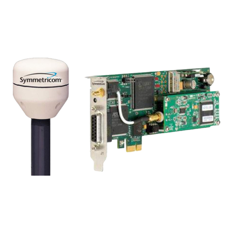
Images of 1 and 2 follow:

User’s Guide – Time and frequency Processor
2
Figure 1-1: Model bc635PCI-V2 Synchronized Generator
GPS Antenna
P/N 142-614-50
bc637PCI V2
A: SMB Antenna Connector
B: J1 Module I/O 15 pin „DS‟
Figure 1-2: Model bc637PCI-V2 (GPS option shown with GPS antenna)
Note: These Time and Frequency Processors will be referred as “TFP” or
“TFPs” for the remainder of the document.
All sections of this manual are applicable to all boards except where noted.

Chapter 1 Introduction
1.2 Key Features 3
1.2 Key Features
All modes of operation are supplemented by flywheel operation. If the
synchronization source is lost, the TFP will continue to function at the last
known reference rate. The following operational modes are supported,
and are distinguished by the reference source.
Mode
Source of Synchronization
0
Time Code - IRIG A, B, G, E, IEEE 1344, NASA 36, XR3 & 2137
1
Free Running (Generator Mode) - 10 MHz Selected Reference (Internal or External)
2
1 PPS - External One Pulse Per Second Input
3
RTC-Uses battery backed on-board real time clock I.C.
4-5
Reserved
6
GPS (bc637) - GPS Antenna/Receiver
Time may be captured in two independent sets of time capture registers.
These registers latch and hold the current time on request. The default
time format is provided in binary form (UNIX seconds through 100
nanoseconds). The TFP Device Register Summary and register formats
are outlined in Chapter 4.
In synchronized generator mode, the TFP uses the selected reference
source to discipline either the standard on-board TCXO (Temperature
Compensated Crystal Oscillator), optional on-board OCXO (Oven
Controlled Crystal Oscillator) or external 10 MHz oscillator. The 10 MHz
oscillator drives all timing functions and outputs on the card. t and 1 PPS
signals are provided as outputs, among others. The advantage of the
OCXO is a better holdover rate should the synchronization source be lost.
The TFP generates IRIG A, B, G, E, IEEE 1344, NASA 36, XR3 & 2137
time codes, synchronized to the reference source. Modulated and DC
level shift formats are produced simultaneously. For more information on
time code formats, refer to:
http://www.symmttm.com/pdf/Gps/an_Time_and_Time_Code_Ref.pdf.
This application note discusses time scales of measurement, digital clock
accuracy, synchronization and Time Code Formats.
A Programmable Periodic (a.k.a. Heartbeat) output is provided. The output
frequency is programmable and may be synchronized to the TFP 1 PPS
signal. The Periodic output programming is discussed in Chapter 5. This
signal may be internally connected to the Event Input to capture the time
associated with the Programmable Periodic edge. The Event Input
configuration is manipulated via the CONTROL Register as described in
Chapter 4. The Periodic square wave output is multiplexed with the DDS
square wave output so that either signal may be selected for output on J1
pin 15.

User’s Guide – Time and frequency Processor
4
A DDS (a.k.a. frequency synthesizer) output may be selected in place of
the periodic rate generator‟s output. The DDS offers a much wider
frequency range than the Programmable Periodic. The DDS is discussed
in more detail in Chapter 4. Note that the DDS and the Programmable
Periodic signals are capable of generating PCI interrupts. Caution should
be taken when using either of these sources with a rate that exceeds the
computer‟s ability to service the interrupts (which may cause the computer
to crash).
A Time Coincidence Strobe output is provided. The Strobe is
programmable from days through microseconds. The strobe also has an
each second mode (referred to in this manual as Minor Time Mode)
programmable to microseconds. The strobe is discussed in more detail in
Chapter 4.
One set of time capture registers is used for event time capture. Time is
captured on the rising or falling edge (user programmable) of the Event
Input signal provided to the TFP via the J1 I/O connector or from the
Programmable Periodic Output signal. The Event Input configuration is
manipulated via the CONTROL Register as described in Chapter 4.
Five maskable interrupt sources are supported. PCI bus levels one
through seven are supported. All interrupt sources may be polled.
Interrupts are discussed in more detail in Chapter 4.
Note: The bc635/637PCI-V2 does not provide interrupts at system start-up
and therefore does not support the PCI Local Bus Specification Revision 2.3
feature of software disable of interrupts at start-up.

Chapter 1 Introduction
1.3 Definition of Terms 5
1.3 Definition of Terms
The following is a glossary of key terms used in the discussion of timing
operations: An expanded glossary of terms is available on-line at:
http://www.symmetricom.com
BCD: Binary Coded Decimal. Also called packed decimal, this is the
representation of each digit of a decimal number by four-bit binary numbers.
So the number 42 would be encoded as 0100 0010 .
Coordinated Universal Time (UTC): See UTC.
COTS: Commercial Off-The-Shelf products or services that are generally
available and not built to customized specifications.
DCLS: Direct Current Level Shift, or digital IRIG.
Discipline: The word discipline, as used in this manual, means to adjust the
frequency of the 10 MHz oscillator to track the incoming reference signal..
DPRAM: Dual Port RAM.
Epoch: A reference time or event. Epoch often refers to a one pulse per
second event.
Event: An event is defined here as a transition of a digital signal (rising or
falling), which can be used to time stamp the event.
Flywheel: To maintain time or frequency accuracy when the reference source
has been lost or removed.
GPS: Global Positioning System. Originally designated NAVSTAR
(Navigation System with Timing And Ranging), GPS was developed by the
US Department of Defense to provide all-weather round-the-clock navigation
capabilities for military ground, sea, and air forces.
HW: Hardware.
IRIG: Serial time format standard maintained by the Inter Range
Instrumentation Group.
ISA: Industry Standard Architecture; desktop PC adapter board specification.
Jamsync: Is the process of abruptly synchronizing with a time reference, as
opposed to gradually adjusting to match up with the time reference.
Major Time: Units of time larger than or equal to seconds.
MHz: A MegaHertz is one million (1,000,000) cycles per second.
Minor Time: Sub-second time to whatever resolution is supported.
MTBF: Mean Time Between Failure, a measure of reliability. The longer the
time span between failures, the more reliable the device.
MTTR: Mean Time To Repair.
NASA 36: National Aeronautics & Space Administration 1-second BCD 36-bit
Time Code.
NIST: National Institute of Standards and Technology, the National

User’s Guide – Time and frequency Processor
6
Measurement Institute in the United States.
OCXO: Oven-Controlled Crystal Oscillator
OS: Operating System.
Packet: A group of bytes conforming to a defined structure. Packets are
usually used in bit serial or byte serial data transmissions to allow framing of
the transmitted data. The bc637PCI-V2 uses data packets to communicate
with the optional GPS receiver.
PCI: Peripheral Component Interconnect, a local bus that supports high-
speed connection with peripherals. It plugs into a PCI slot on the
motherboard.
PCISIG: PCI Special Interest Group.
PCM: Pulse Code Modulation.
Periodic: A programmable frequency that is obtained by dividing the TFP
reference frequency. Periodics are sometimes referred to as “heartbeats.”
PICMG: PCI Industrial Computer Manufacturers Group.
PLL: Phase-Locked Loop.
ppm: parts per million.
pps: pulse per second.
RAM: Random Access Memory.
Resolution: Resolution of a time code refers to the smallest increment of
time, whether it is days, hours, seconds, or other.
Strobe: The strobe is a programmable “alarm.” It compares the reference
time with a user-programmed time, and outputs a signal when the two values
are the same. The signal is indicated by a transition from low to high voltage.
The duration of the signal is equal to the resolution of the strobe comparators
(i.e., the reference time and the programmed time). The Strobe function is
also referred to as Time Compare.
SW: Software.
TCXO: Temperature Compensated Crystal Oscillator
TFP: Time and Frequency Processor is the name given to the bc635PCI-V2
family of products.
USNO: U.S. Naval Observatory, in Washington, D.C., where the atomic clock
that serves as the official source of time for the United States is maintained.
UTC: The international time standard is called Universal Coordinated Time or,
more commonly, UTC, for “Universal Time, Coordinated”. This ITU standard
has been in effect since 1972. UTC is maintained by the Bureau International
de l‟Heure (BIH), which forms the basis of a coordinated dissemination of
standard frequencies and time signals.
VCXO: Voltage-controlled Crystal Oscillator.

Chapter 1 Introduction
1.4 Performance Specifications Input 7
1.4 Performance Specifications Input
1.4.1 Time Code Translator
Formats
IRIG A, B, G, E, IEEE 13441, NASA 36, XR3 & 2137
(AM/DCLS)
Carrier Range
± 20 PPM
Time Accuracy2
< 5 μsec. (AM with carrier frequencies 1 kHz or greater)
< 1 μsec. (DCLS)
Flywheel Accuracy
Typical Drift < 2 Milliseconds Per Hour
AM Modulation Ratio
2:1 to 4:1
AM Input Amplitude
1 to 8 Vp-p
AM Input Impedance
5 k:, AC Coupled
DCLS Input
5V HCMOS, >2V high, <0.8V low, 270Ω
1IEEE 1344 compliance –The translator processes the 27 control function
bits of IRIG B time code as set forth in IEEE 1344.
2May require a calibration to attain this accuracy. See “Time Code Calibration”
in Chapter 3.
1.4.2 Output Time Code Generator
Formats
IRIG A, B, G, E, IEEE 1344, NASA 36, XR3 & 2137
(Modulated/DCLS)
Modulation Ratio
3:1 ± 10%
Output Amplitude
3V p-p ±10% (fixed) into 50 Ohms
DC Level Shift
5V HCMOS, >2V high, < 0.8V low into 50Ω
1.4.3 PCI Bus Characteristics
Specifications
Designed Per PCI Local Bus Specification, Revision
2.31
Size
Single-Width 6.875” x 4.2”
Interrupts
Auto Configurable IRQ Level 2 –15
Power (bc635PCI-V2)
+5V @ 700 mA
+12V @ 50 mA
Power (bc637PCI-V2)
+5V @ 800 mA
+12V @ 50 mA
Power (bc635PCI-V2-OCXO)
+5V @ 800 mA (1.1A at start up)
+12V @ 50 mA,
Power (bc637PCI-V2-OCXO)
+5V @ 900 mA (1.2A at start up)
+12V @ 50 mA
1The bc635/637PCI-V2 does not provide interrupts at system start-up and
therefore does not support the PCI Local Bus Specification Revision 2.3
feature of software disable of interrupts at start-up.

User’s Guide – Time and frequency Processor
8
1.4.4 Digital Inputs
Event Capture
5V HCMOS,>2V high, < 0.8V, 270 Ω, zero latency,
Rising or Falling Edge Triggered, 20 nSmin. width, 250
nSmin. period
External 1 PPS
5V HCMOS, >2V high, < 0.8V low, 270 Ω,
Rising Edge On Time,20 nS minimum width
1.4.5 Digital Outputs
1 PPS
5V HCMOS, >2V high, < 0.8V low into 50 Ω , Rising Edge On
Time, 60 μS Positive pulse
Periodic
5V HCMOS, >2V high, < 0.8V low into 50 Ω , Rising Edge On
Time (selectable on time control), <1 Hz to 250 kHz, square
wave
DDS
5V HCMOS, >2V high, < 0.8V low into 50 Ω , Rising Edge On
Time (selectable on time control), 1/1e7 –1e8 Hz, <2 nS jitter
p-p, square wave
Strobe
5V HCMOS, >2V high, < 0.8V low into 50 Ω , 1 μS Positive
pulse, variable delay
1, 5, 10 MHz clock
5V HCMOS, >2V high, < 0.8V low into 50 Ω (see Chapter 3
for signal characteristics)
Time Code DCLS
5V HCMOS, >2V high, < 0.8V low into 50 Ω
1.4.6 External 10 MHz Oscillator Input
Digital 40% to 60% Duty Cycle (or) Sine wave, 0.5 to 8Vp-p, >10k Ω
1.4.7 External 10 MHz Oscillator DAC
Jumper selectable 0-5VDC or 0-10VDC into 1kΩ
Board Jumpers (JP1, JP2, JP3)
The following is a list of the hardware jumpers on the bc635/637PCI-V2
board:
1. JP1 is a 2mm jumper that is the RTC battery connect switch. The RTC
battery is a non-rechargeable lithium cell with 48 mAh capacity. When
the card is not powered and the RTC battery has not been disabled,
the RTC draws about 20 uA which will provide >100 days of RTC
operation. Long-term storage of the card should be done only after
issuing the Disconnect RTC Battery command or by the manual
disconnection of the jumper on JP1. The factory configuration places
the 2mm J1 jumper ON.

Chapter 1 Introduction
1.4 Performance Specifications Input 9
2. JP2 is the 1,5,10 MPPS or 10 MHz oscillator select switch. The factory
configuration places the 2mm JP2 jumper on pins 1-2 which will allow
for the software selection of 1, 5 or 10 MPPS for the output on J1 pin
13. When the jumper is in the 2-3 position, the output on J1 pin 13 is a
buffered signal from the 10 MHz oscillator.
3. JP3 is the DAC voltage range switch. When the jumper is OFF, the
DAC voltage is 0-5 VDC; when ON the voltage is 0-10 VDC. Both
oscillators that are offered for this board have 0-5 VDC control voltage
ranges, therefore the 2mm jumper is not factory installed. If an external
oscillator requires a 0-10 VDC control voltage range, a 2mm jumper
should be placed on JP3.
1.4.8 Environmental Specifications
Temperature
Operating
0°C to +70°C (32°F to +158°F)
Non-Operating
-30°C to +85°C (-22°F to +185 °F)
Relative Humidity
Operating/Non-Operating
To 95% RH, non-condensing
1.4.9 Antenna Specifications (bc637PCI-V2 only)
To operate in the GPS Synchronized Generator mode, the bc637PCI-V2 unit
requires an external antenna. The standard antenna kit supplied with this
option is part number 142-614-50 that includes 50 feet (15.24 meters) of
coaxial cable and antenna mounting hardware.
Part Number
Description
142-614-50
L1 Antenna w/50‟ RG59

User’s Guide – Time and frequency Processor
10
Figure 1-3: Antenna parts
The antenna is housed in completely waterproof packaging designed to
withstand the elements. When the four UNC 4-40 screws are loosened, the
antenna module detaches as shown below, exposing the TNC connector.
Figure 1-4: Antenna with TNC connector
Warning: Model bc637PCI-V2 supplies +5 VDC to the antenna. Connection
to an alternate antenna may impact the board and/or antenna functionality.
Other manuals for bc635PCI-V2
1
This manual suits for next models
3
Table of contents
Other Symmetricom Computer Hardware manuals
Popular Computer Hardware manuals by other brands

Ratoc Systems
Ratoc Systems Ultra SCSI (FAST-20) Card Bus PC Card... product manual

iSystem
iSystem Infineon AGBT USB-C Active Probe user manual

Connect Tech
Connect Tech CANpro/104-Plus Opto user manual

Areca
Areca ARC-1212 user manual

Kontron
Kontron COM Express Extension specification

Art
Art Personal Processor Series user guide