Commissioning
The DIGIMATIC can be calibrated automatically, manually or by a combi-
nation of the two methods. Usually, automatic calibration is the simplest
method, particularly when the vessel can be filled to cover the probe.
Manual calibration is useful when a number of probes in similar applications
need to be set. Once the correct calibration has been determined and not-
ed, on one system, the remainder can be set to the same setting.
Display Functions
The display (fig 3) shows a number of different values depending upon
whether the unit is in manual or auto mode, and cal or park mode.
Park Mode
In normal operation the display shows a value representing the capacitance
measured by the probe at the time.
Pressing the button will cause the display to show uxxx followed by rxxx.
Pressing the button will cause the display to show cxxx followed by rxxx.
cxxx is the probe covered value measured during calibration, uxxx is the
uncovered value and rxxx is the relay operating point which the Digimatic
calculates and is half way between the two measured values.
Note: The settings are "view only" in park mode, they cannot be altered.
Cal Mode - auto/man switch set to auto
In this mode, pressing the button will cause the unit to measure and
display the uncovered value and recalibrate the relay operating point if
necessary. Pressing the button (with the probe covered) will cause the
unit to measure and display the covered value, again recalibrating the relay
operating point if necessary.
Cal Mode - auto/man switch set to man
In this mode, pressing the button will cause the display to momentarily
display the present relay operating point and then to increment the setting
slowly and then rapidly to set a higher operating point. Pressing the
button will cause the display to momentarily show the current relay operating
point, and then decrement the setting, slowly and then rapidly.
Once adjusted in manual mode, any previous settings will be lost. The cxxx
reading will be 1 above the relay operating point and the uxxx reading 1
below.
Note: Always return to “Park” (after calibration)
Earth
Bond
E
N
110v
24v
0v
230v
Introduction
Installation
The DIGIMATIC is a fixed point Level Controller incorporating a microcom-
puter which is used to automatically calibrate the probe to suit the material
being detected. Full manual override facilities are included. The unit has full
ATEX approval for use in dust hazard installations, such as flour mills, saw
mills or any application where dust may be present.
The DIGIMATIC employs a power shield to minimise the effect of material
adhering to the probe making it ideal for detecting most materials including
sticky or viscous types. It is equally suited to both liquids and solids . The
probe may be a solid rod, metal plate or wire rope.
The self contained DIGIMATIC is normally supplied with a loose probe,
available as a stainless steel rod in standard lengths of 100mm, 1 metre or 2
metres, or as a 10 metre wire rope suspension probe and weight. The probe
should be screwed to the DIGIMATIC. Prior to attachment, the probe length
can be reduced or increased, if desired, but see notes a) and b) regarding
minimum surface area.
Connections
A thread locking compound is already applied to the probe fixing stud of the
DIGIMATIC. This will prevent the probe rod from vibrating loose. Once fitted,
the compound is fully hardened after 20 minutes.
DIGIMATIC will operate on 110V/230V ac 50/60Hz or 24V dc supplies (Um).
The unit may be wired in ordinary un-screened cable of any length and need
not be separated from other cables.
A SUPPLY EARTH IS ESSENTIAL!
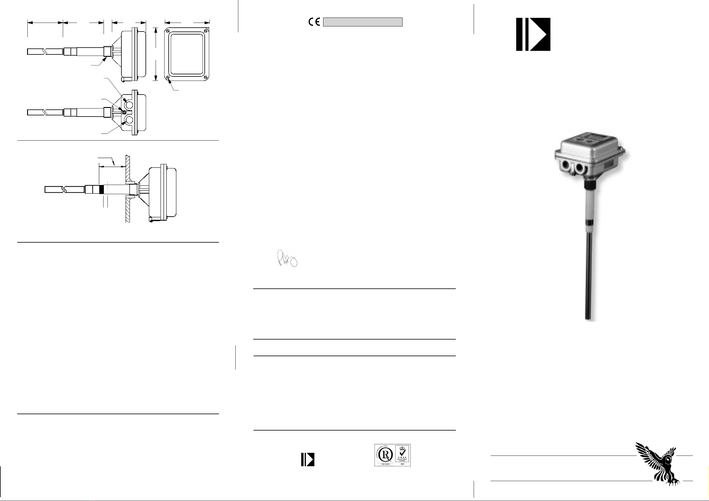
When mounting the DIGIMATIC, care must be taken to ensure that the
exposed end of the power shield protrudes into the container. See fig. 6.
Mount unit securely to minimise vibration.
Connect in accordance with fig 1, and set High/Low switch to required
position (see fig 2), ensure that cable gland and back cover are fully tight-
ened when finished. The DIGIMATIC has two 20mm cable entries, one of
which is blank, the blank may be drilled out carefully if required; it must not
be knocked out. All cable glands must be ATEX approved, IP65 rated. The
unit should be wired and earthed in accordance with appropriate Electrical
Regulations. The unit must be earthed and the terminal MUST be bonded to
the earth bond stud.
On metal containers, unit earth MUST be bonded to the container. If the
container is non-metallic, metal flanges or couplings used to mount probe
should be bonded to earth. This also applies to probes mounted in wooden
or plastic tops of metal bins.
Fail Safe Setting
The “High/Low” switch (fig 2), sets the fail safe mode. In the “High” position,
the relay is de-energised with material present. In the “Low” position, the
relay is energised with material present. Normally, the “High” position is used
for high level probes and the “Low” for low level probes. Intermediate probe
settings depend upon individual requirements.
Um Stabilised 24V DC supply, -6% to +2%
FIG 3
Covered/Raise Button
Un-covered/Lower Button
4 Digit Display
Timer Button
Power On LED
Calibrating LED
Output LED
Switch Functions:
SW1 = High/Low
SW2 = Cal/Park
SW3 = Auto/Man
Automatic Calibration - material available
1) Set Cal/Park switch to Cal and Auto/Man switch to Auto. The Cal LED will
flash.
2) Ensure that the probe is uncovered and press and hold the button.
The display will show uxxx followed by rxxx.
3) Fill the vessel sufficiently to cover the probe and then press the
button. Display will show cxxx followed by rxxx.
4) Return the Park/Cal switch to park. The unit is now calibrated. uxxx &
cxxx values can be viewed but not altered by pressing the & buttons.
Semi Automatic Calibration - material not available
5) Follow steps 1 & 2 above.
6) Set Cal/Park switch to Park and press the button. Note the uxxx read-
ing but ignore the rxxx reading. Return the Cal/Park switch to Cal and set
the Auto/Man switch to Man.
7) From the table below, select the nearest material to the type to be detect-
ed and add the value to the uxxx reading determined in (6).
8) Press the button to raise the reading and the button to lower the
reading to achieve the calculated setting.
9) Return the Cal/Park switch to Park and press the & buttons to
confirm that the relay operating point rxxx is correctly set. The uxxx & cxxx
settings will be one below and one above the readings.
Table of Typical Settings
Material Type Increment
Light +15
Medium +30
Heavy +60 or greater
Time Delay
The DIGIMATIC has an adjustable delay from 0 to 60 seconds, the timer
operating on both material arriving and leaving. To set the time delay, pro-
ceed as follows.
10) Set the Cal/Park switch to Cal.
11) Press and hold the button. The display will show t000 which incre-
ments from zero and adds one second each time the button is pressed. Re-
lease the button when the required delay time is shown.
12) Return the Cal/Park switch to Park and press to confirm the timer
setting.
13) The timer can be altered to a longer or shorter delay by repeating the
procedure from 10) above.
NOTES:-
a) The DIGIMATIC sensitivity is proportional to the surface area of the
probe. When using a 16mm dia. probe the minimum length to use, for the
majority of materials, is 200mm. This should be treated as the minimum if
possible.
If the probe length needs to be reduced to less than 200mm, the surface
area should be maintained. This can be achieved by increasing the
diameter, by fitting a metal tube over the probe, or by bending the probe
rod. In certain high density materials it may be possible to reduce the
length without compensation.
b) Synatel offer a free product test service. To use this service, supply 2
litres of product in a sealed container (to prevent ingress or loss of
moisture), the product will be tested and its suitability confirmed. Your
should also notify us of any safety precautions which should be observed
during testing.
(Supply suitable COSHH datasheet).
* IMPORTANT *
Earth
Bond
E
N
110v
24v
0v
230v
Cal/Park Switch
Auto/Man Switch
High/Low Switch
SW2 SW3 SW1
FIG 2
FIG 1
ELECTROSTATIC RISK - Ensure that the enclosure is not subject to
charging in end application.
Relay
Terminals:
Um : 240V
Ii : 2.5A non-inductive