Synergy SYPM S5BC User manual

Synergy Power Module - SYPM S5BC
Installation Instructions
Part No. CDCS000309 Rev B
Page 11/11
Synergy Lighting Controls Conyers Ga, 30012
TEL : (800)-533-2719 www.Synergylightingcontrols.com
WARNING
To reduce the risk of death, injury or property damage from re, electric shock, cuts,
abrasions, falling parts, and other hazards:
• Service of the equipment must be performed by qualied service personnel.
• Installation and maintenance must be performed by a person familiar with the construction
and operation of this product and any hazards involved. All applicable codes and ordinances
must be followed.
• Read this document before installing, servicing, or maintaining this equipment. These
instructions do not cover all installation, service, and maintenance situations. If your situation
is not covered, or if you do not understand these instructions or additional information is
required, contact Synergy Lighting Controls.
WARNING
Before installing, servicing, or maintaining this equipment, follow these general precautions.
To reduce the risk of electrocution:
• Make sure the equipment is properly grounded.
• Always de-energize any equipment before connecting to, disconnecting from, or
servicing the equipment.
To reduce the risk of re:
• Use supply conductors with a minimum installation temperature rating as specied.
To reduce the risk of personal injury from cuts, abrasions:
• Wear gloves to prevent cuts or abrasions from sharp edges when removing from
carton, handling and maintaining this equipment.
• Do not install a damaged equipment.
Synergy Lighting Controls, a division of Acuity Brands Inc., assumes no responsibility for claims arising out of
improper or careless installation or handling of this product.
SAVE THESE INSTRUCTIONS
IMPORTANT SAFETY INSTRUCTIONS
READ AND FOLLOW ALL SAFETY INSTRUCTIONS!
SAVE THESE INSTRUCTIONS AND DELIVER TO OWNER AFTER INSTALLATION
!
!
DISCONTINUED

Synergy Power Module - SYPM S5BC
Installation Instructions
Part No. CDCS000309 Rev B
Page 2 1/11
Synergy Lighting Controls Conyers Ga, 30012
TEL : (800)-533-2719 www.Synergylightingcontrols.com
Install the Power Modules in the Enclosure.
Install the first module in the top position as shown, then install additional
modules in the positions below. Make sure the ribbon cable stays at the back
of the enclosure behind the installed modules.
Test Power Module Operation
Turn on the cabinet power supply. Use the ON/AUTO/OFF switch to test the module. All module outputs on each
Simply5 network should turn ON when the switch is in the ON (up) position and turn OFF when the switch is in the
OFF (down) position. When testing is complete, return the switch to the AUTO (center) position. The ON/AUTO/
OFF switch MUST be in the AUTO position for normal system operation and control from the system controller and
system low voltage inputs.
4
5
1
2
3
Set Each Module Address to a Unique Address
Rotate the address wheel to set the ID. Set the ID of the top module
at “1” (as shown), the second at “2” and so on.
Refer to the instructions on the following pages for complete details on the steps outlined below.
Quick Setup Guide SYPM S5BC Power Module
Connect Each Intelligent Ballast Control (IBC) Network
ON ON
ON
Connect the Ribbon Cable to Each Module
DISCONTINUED

Synergy Power Module - SYPM S5BC
Installation Instructions
Part No. CDCS000309 Rev B
Page 31/11
Synergy Lighting Controls Conyers Ga, 30012
TEL : (800)-533-2719 www.Synergylightingcontrols.com
1. Always disconnect all power.
2. Install in accordance with the National Electrical
Code and any other codes which may apply.
3. Use only as intended and at the listed voltage.
1. MOUNT TOP MODULE
Starting at the TOP of the cabinet, mount the module
by setting the bottom tabs in the slots at the back
of the cabinet then securing the top with the screws
provided.
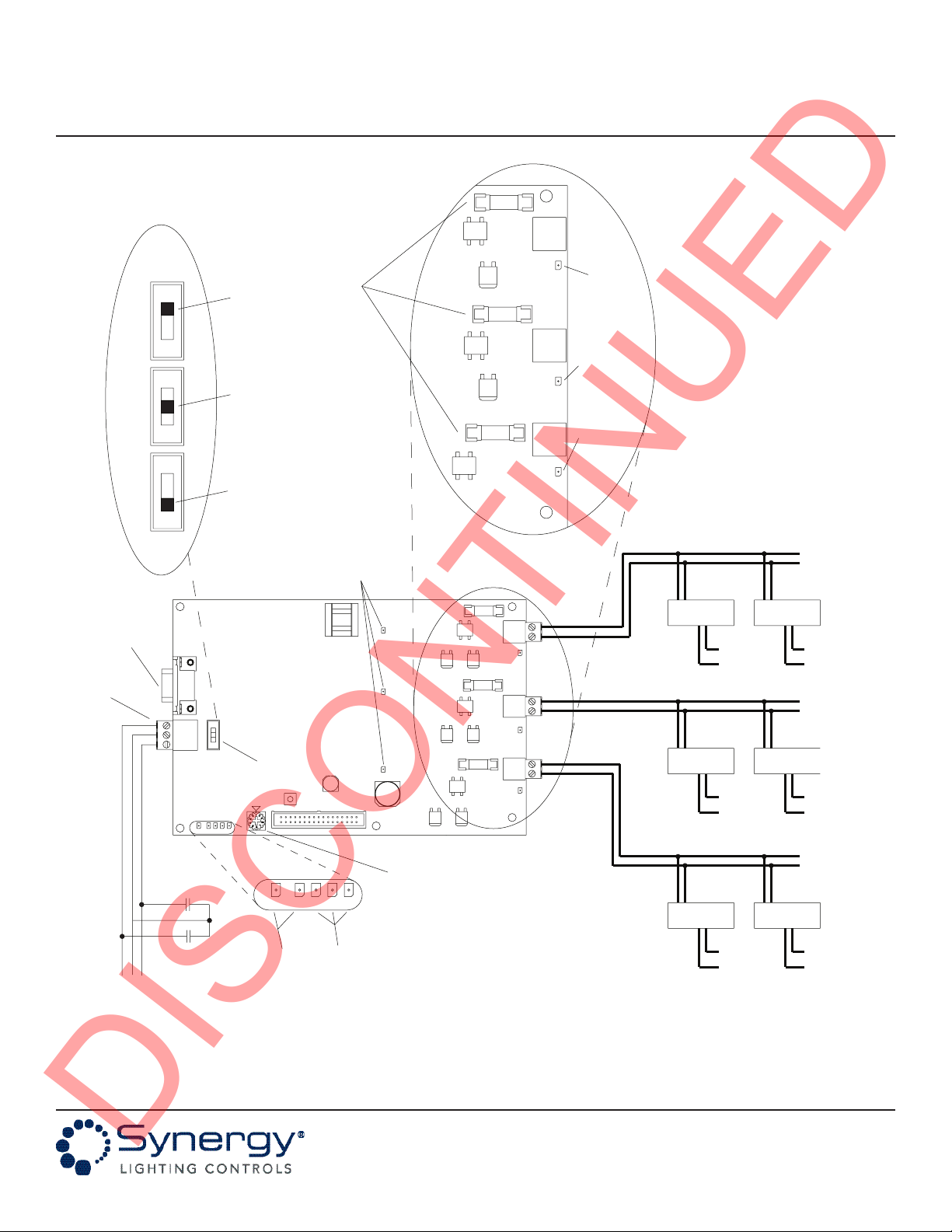
2. SET MODULE ID AND CONNECT RIBBON CABLE
Rotate the power module card ID switch to the
address 1 position. (See Figure 1) Plug the male
connector on the ribbon cable into the female socket
on the power module. Ribbon cable installs behind
the modules.
3. Repeat steps 1 & 2 for additional modules,
incrementing the power module card ID switches by
1 from the top of the cabinet down.
4. CONNECT SIMPLY5 NETWORK OUTPUTS TO
SIMPLY5 OR DALI BALLASTS
Each DALI/SIMPLY5 has a pair of control wires. Each
control pair should be terminated on a
DALI/SIMPLY5 network plug-in connector on the
power module, (See Figure 1). Refer to Synergy
supplied Installation drawings and any additional
accessory instructions or project specifications for
details. A maximum of 64 DALI/SIMPLY5 ballasts
can be connected to a single SIMPLY5 network.
5. START-UP POWER MODULES TO ALLOW
MANUAL LIGHTING CONTROL
1. Verify the three “Manual Override Switches” are in
the ON position. (See Figure 1)
2.Turn on circuit breaker for the enclosure power
supply.
3.Turn on the circuit breakers supplying power to
the SIMPLY5 ballasts. Use the manual override
switches for convenient on/off override of the
lighting.
6. POWER MODULE CONFIGURATION
IBC power modules and DALI/SIMPLY5 groups are
fully programmable with the addition of the SYSC
system controller. Refer to the SYSC system
controller installation instructions and Synergy
Operation Manual for more information.
Before You Start
Important Module Installation Notes
1. Install power modules in cabinet starting at the
top. Plug ribbon cable into each module before
installing the next module. Ribbon cable installs
behind modules.
2. The Intelligent Ballast Control (IBC) output
connections are either Class 1 or Class 2 circuits,
and should be installed in accordance with the
National Electric Code and any local codes which
may apply. For specific information on conductor
routing for your application, consult the ballast
manufacturer’s recommendations.
3. A maximum of 64 DALI/Simply5 ballasts can be
connected to a single DALI/Simply5 network. The
SYPM S5BC power module contains three Simply5
networks, with each network containing a dedicated
controller and power supply. Each SYPM S5BC
power module supports a maximum total of
192 DALI /Simply5 ballasts.
Module Installation and Wiring
The SYPM S5BC intelligent ballast control module can control either DALI ballasts or SIMPLY5 ballasts. Connection to, and
control of, either ballast type from the SYPM S5BC power module and a Synergy system are identical.
DISCONTINUED

Synergy Power Module - SYPM S5BC
Installation Instructions
Part No. CDCS000309 Rev B
Page 4 1/11
Synergy Lighting Controls Conyers Ga, 30012
TEL : (800)-533-2719 www.Synergylightingcontrols.com
Synergy Lighting Controls warrants all equipment to be free from defects in manufacturing under normal and proper storage,
installation, and operation for a period of one (1) year. Our guarantee liability extends only to the repair or replacement of the
defective part and no labor charges for correction of the defect by repair or replacement will be honored by Synergy Lighting
Controls unless prior written authorization has been granted by our Customer Service Department.
Warranty
Troubleshooting Procedures
If the IBC power module control outputs do not come on,
follow these steps:
1. Verify the correct input voltage is present at the
line voltage input of the DALI/SIMPLY5 ballast.
2. Verify the cabinet power supply LEDs are on and
the RIBBON CABLE is properly connected to the
power supply and the module.
3. Switch the MANUAL OVERRIDE SWITCH on the
power module to the “ON” position. All controlled
DALI/SIMPLY5 loads should turn ON on each
DALI/SIMPLY5 network.
4. If the loads switch ON/OFF using the manual over-
ride switch but do not respond to the controller,
check the system programming. See the Synergy
Operation Manual for programming instructions.
5. If the loads will not respond to controller com-
mands, check the voltage on each DALI/SIMPLY5
network. There should be 9.5 to 22 volts DC
across each DALI/SIMPLY5 network control wire
pair. If no voltage is present, check the appropri-
ate DALI /SIMPLY5 network fuse.
If after performing the above tests one or more cir-
cuits still do not turn on, contact Synergy Lighting
Controls Technical Service department between
the hours of 8 AM and 5 PM EST, Monday - Friday,
at 800-533-2719.
Visit Synergy Lighting Controls on the internet at http://www.synergylightingcontrols.com/controls for further information
on products, technical data and installation instructions.
DISCONTINUED

Synergy Power Module - SYPM S5BC
Installation Instructions
Part No. CDCS000309 Rev B
Page 51/11
Synergy Lighting Controls Conyers Ga, 30012
TEL : (800)-533-2719 www.Synergylightingcontrols.com
Figure 1 - SYPM S5BC Wiring Detail
Note: DALI and SIMPLY5 ballast connections are identical.
ON
COM
OFF
IBC NETWORK
COMMUNICATION
STATUS LEDs
IBC
NETWORK
FUSES
NETWORK 1
POWER
INDICATOR
LED
F3
F2
F1
RS232
PORT
CARD ID SWITCH
ALL MODULES IN EACH CABINET
MUST BE AT A UNIQUE NUMBER.
START AT THE TOP OF THE
CABINET BEGINNING WITH "1"
HOA
AUTOOFF ON
FORCE ON
FORCE OFF
STATUS BUS 3V 5V 12V
12V5V3VBUSSTATUS
POWER SUPPLY
INDICATORS LEDs
NETWORK BUS
COMMUNICATION
LEDs
F3
F2
F1
N
LINE
N
LINE LINE
N
LINE
N
N
LINELINE
N
AUTOMATIC
POSITION
OVERRIDE
OFF POSITION
OVERRIDE
ON POSITION
ONOFF AUTOAUTOOFF ONONOFF AUTO
TO ADDITIONAL
BALLASTS
MANUAL
OVERRIDE
SWITCH
TO ADDITIONAL
MODULES
THIS CABINET
IBC LOOP 1
VIOLET
REMOTE
OVERRIDE
TERMINAL
BLOCK
VIOLET
IBC LOOP 2
VIOLET
VIOLET
VIOLET
VIOLET
IBC LOOP 3 TO ADDITIONAL
BALLASTS
TO ADDITIONAL
BALLASTS
NETWORK 2
POWER
INDICATOR
LED
NETWORK 3
POWER
INDICATOR
LED
DISCONTINUED
Table of contents
Popular Control Unit manuals by other brands

Roc-Solid
Roc-Solid SC-2420 user manual

Watts
Watts 995 Series Installation, Service, Repair Kits, Maintenance

HDanywhere
HDanywhere MOD44 user manual

elsner elektronik
elsner elektronik IMSG-UC-2H Technical specifications and installation instructions

BENDIX
BENDIX R-12DC Service data

H3C
H3C PSR3000-54A manual

Boundary Devices
Boundary Devices Nitrogen series user manual

Siemens
Siemens Simatic S7-300 manual

Azbil
Azbil ACTIVAL VY519 J Series Specifications & instructions

Vertiv
Vertiv eSure R48-1000e3 user manual

Unitronics
Unitronics V200-18-E3B manual

Silicon Laboratories
Silicon Laboratories EFR32 G1 Series Reference manual