Synetica enLink Zone Plus User manual

enLink Zone Plus User Guide
LoRaWAN Wireless environmental sensor
•LoRa long range wireless
•Battery or externally powered
•Built in sensors for:
•Temperature (°C)
•Humidity (%RH)
•Carbon Dioxide (CO2 )*
•Presence (PIR)*
•Barometric Pressure (Pa)
•Light level (lux)
•Volatile Organic Compounds (VOC’s)
•Sound (dBA)*
Temperature
Humidity
Light level
VOC’s
CO2
Pressure
Motion
Sound
enLink Zone Plus accurately measures multiple environmental
parameters including room temperature, humidity, CO2, VOC’s, light
level, pressure and sound level*.
Volatile Organic Compounds (VOC’s) from paints (such as
formaldehyde), lacquers, paint strippers, cleaning supplies,
furnishings, office equipment, glues, adhesives and alcohol can be
detected and reported down to the ppm range.
Readings are transmitted to the cloud using long range LoRa wireless,
where the data can be displayed and analysed.
The unit can be either externally or battery powered for maximum
flexibility.
A built in USB port allows all parameters including air quality data,
wireless signal strength and wireless network configuration to be
viewed and set using simple menus via any USB enabled host such
as a PC or Mac.
Features
•
Multiple sensor options*
•
LoRa long range wireless
•
Frequency Range 863-870MHz*
•
Frequency Range 902-928MHz*
•
Up to +18dBm Tx Power
•
Built in USB port for power and
configuration
•
Battery or externally powered
•
CE and FCC Compliant
•
RoHS compliant
•
Made in the UK
*Model dependent, see Selection Guide
section
1.
2.
3.

SYNETICA enLink Zone Plus User Guide Rev 1.6
1. Introduction
LoRa devices can be configured using OTAA (Over-the-Air-Activation) or ABP (Activation-by-Personalisation).
OTAA is the most secure way to connect a device to the LoRa network. In OTAA, the device performs a Join-procedure
with the network, during which a dynamic DevAddr (device address) is assigned and security keys are negotiated with the
device.
ABP allows you to set the DevAddr as well as the security keys in the module. This is simpler than OTAA as there is no
Join procedure, however, it is less secure than OTAA.
This guide will illustrate using OTAA as it is the most secure and flexible method.
The OTAA configuration requires the following parameters to be correctly set:
•DevEUI: End-device Identifier. It is unique for every device and is set at device manufacture.
•AppEUI / JoinEUI*: Application Identifier. Used to identify the end application.
•AppKey: Application key. Used to create the session keys.
*Note: In LoRaWAN 1.1, AppEUI was renamed to JoinEUI.
For many applications Synetica can supply enLink units with the above parameters pre-configured, so providing the LoRa
gateway has the matching keys the join process will happen automatically once the enLink unit is in wireless range and
switched on.
The DevEUI is always set at device manufacture and is unique. The device AppEUI and AppKey can easily be set via the
USB connection if required and the process is detailed later in this document.

SYNETICA enLink Zone Plus User Guide Rev 1.6
2. Join enLink devices to the LoRa network
Depending on the LoRa Network Server used, enLink devices in wireless range and with the correct AppEUI and AppKey
settings set will automatically join the LoRa network when they are first powered up.
enLink Zone Plus Label
The unique DevEUI is printed on all enLink devices and is also present in the QR code. The DevEUI can be used to identify
the device once joined to the network.
Mod
el
ENL-ZNP
Environmental sensor
Input 12-24Vdc
DevE
UI
00-04-A3-0B-00-04-27-DB
0010123
www.synetica.net
Made in the UK
Serial
No:

SYNETICA enLink Zone Plus User Guide Rev 1.6
3. Powering the unit
To power the device ON, slide the power switch to the EXT position and insert the 4 x AA sized Lithium 3.6V batteries
taking great care to insert them the correct way around. Locate the plus (+) and minus (-) signs on the battery and use the
plus (+) and minus (-) guides on AA battery holders to insert the batteries in the proper direction. All four batteries face in
the same direction.
Be sure to insert the minus (-) end first and remove the plus (+) end first when replacing the batteries.
Lithium batteries have very high energy capacity and a great degree of care should be exercised to ensure
that all batteries are new, from the same manufacturer, installed the correct way around and are not in any
way damaged. Refer to Section 11 Battery Installation / Replacement for more details.
Check that the batteries are correctly inserted and then slide the power switch to BATT.
Alternatively, the unit can be externally powered from a PSU with12V to 24V DC (rated 200mA or greater). See section 12
for more information on externally powering the unit. Apply correct power to the unit, carefully observing the polarity and
slide the power switch to EXT.
Note that the unit can only be battery powered or externally powered. When the switch is in the BATT position, any external
power source is automatically disconnected. When in the EXT position, the batteries are automatically disconnected.
To power the device ON, remove the rear cover of the enLink Zone Plus by inserting a small screwdriver blade into the
slots on the bottom of the unit as shown below.
Cover Removal
Locate the power switch and using small screwdriver gently slide the power switch towards the BATT position marked on
the unit as shown, or apply external power (12V-24V DC) to the unit and slide the power switch to EXT.

SYNETICA enLink Zone Plus User Guide Rev 1.6
Switch to the BATT position
Once powered ON, the enLink device will send a Join request message to the gateway. The Status LED will blink RED as
shown below whilst the Join process is taking place. Depending on factors such as signal strength, RF interference etc
the Join process may take several seconds to complete.
EXT
BATT

SYNETICA enLink Zone Plus User Guide Rev 1.6
Blinking Red LED –Attempting Join
When the device has successfully joined the network the Mode LED will blink GREEN for several seconds to show that the
Join has been completed. The LED’s will then switch off to conserve the batteries.
Devices which have Joined the network appear in the Conduit LoRaWAN - > Devices menu as shown previously.
4. Setting / changing the enLink LoRa keys
For many applications, Synetica can supply enLink Zone Plus units with the LoRa AppEUI and AppKey parameters pre-
configured to your requirements, whereby if the LoRa gateway has matching keys the join process will happen
automatically once the Zone Plus unit is in wireless range and switched on.
The DevEUI is always set at device manufacture and is unique. The device AppEUI and AppKey can easily be set via the
USB connection as detailed below.
Remove the enLink Zone Plus board from its enclosure as shown previously. Take care when removing the board from
the front part of the enclosure and only use the slots provided at the bottom of the board to gently lift the board up and
out of the enclosure.
Connect a micro USB cable to the enLink unit.
There are two USB connectors on the enLink Zone Plus, so be sure to connect to the correct USB port as shown in the
image below.

SYNETICA enLink Zone Plus User Guide Rev 1.6
The device will attach to a COM port on your PC.
Using a terminal program (e.g. Teraterm https://ttssh2.osdn.jp/) connect to the COM port used by the enLink device.
To verify which COM port is being used, check the Windows™ Device Manager (In Windows - Click the Start button, type
device manager into the search box and tap Device Manager on the menu.) Expand the Ports (Com & LPT) menu as
shown below.
In your terminal program press the Enter key. An enLink summary screen will appear as shown below. The default
password is the last four digits of the displayed DevEUI, in the screen below this is 9377.
enLink logon screen
USB Connector

SYNETICA enLink Zone Plus User Guide Rev 1.6
The screen below will show with the enLink Main Menu options. Enter Qto enter the Quick Start Menu.
enLink Main Menu
The Quick Start Menu contains only the parameters that normally need to be configured to setup the device and join the
LoRa network.
From the Quick Start Menu you can change the AppEUI and AppKey.
Quick Start Settings Menu
From the Quick Start Settings Menu, access the AppEUI setting by entering E. Enter the 16 character AppEUI using
numbers and letters a to f. Do not include spaces or any other characters. Pressing Swill enter the default AppEUI which
you can then edit. Press Enter when the key is correctly entered to return to the Quick Start Settings Menu.
AppEUI setting
From the Quick Start Settings Menu access the AppKey setting by entering K. Enter the 32 character Appkey using
numbers and letters a to f. Do not include spaces or any other characters. Pressing Swill enter the default AppKey which
you can then edit. Press Enter when the key is correctly entered to return to the Quick Start Settings Menu.
AppKey setting
Press Xfrom the Quick Start Settings Menu to return to the enLink Main menu.
The header will show ** Reboot Required ** as shown below. The new key settings will not take effect until the enLink
device is restarted. Enter Rto reboot followed by OK. The device will restart with the entered AppEUI and AppKey and
attempt to join the LoRa network.
Reboot Required notification
Check the Conduit LoRaWAN -> Devices menu detailed previously to verify that the enLink device has joined successfully.

SYNETICA enLink Zone Plus User Guide Rev 1.6
5. Live Menu
enLink Zone Plus incorporates a live data screen which shows all readings and device status for easy data validation. To
enter the Live status screen, from the Main Menu enter c for Configure Device followed by dfor Live readings display. A
screen similar to the one below will show. The sensors will vary according to the enLink Zone Plus model and the installed
sensors.
Live Display
6. Configuration Menu
The enLink Zone Plus configuration menu allows you to view current sensor readings and also to change various functions
of their behaviour such as calibration data. To enter the Configure Device menu press cfrom the main menu. A screen
similar to the one below will show. The exact parameters shown will vary according to the Zone Plus model and sensors
fitted.

SYNETICA enLink Zone Plus User Guide Rev 1.6
7. CO2Sensor Auto Calibration Configuration
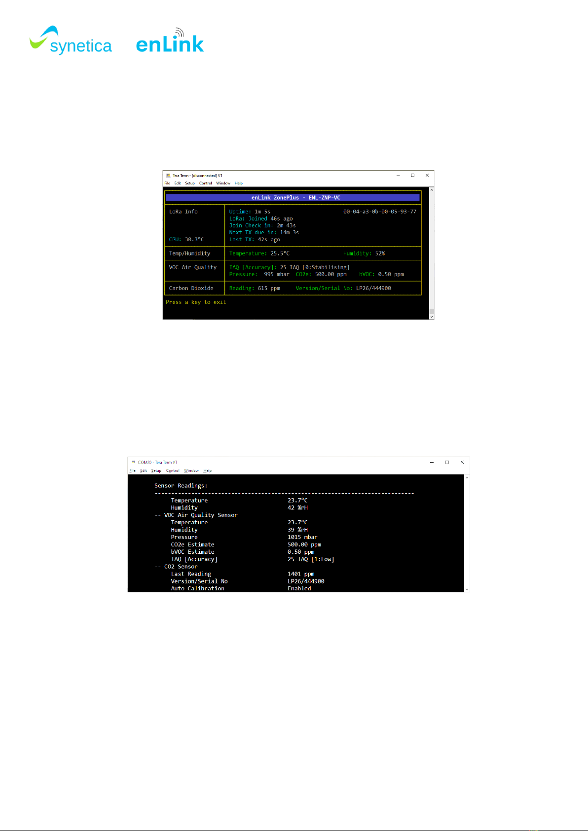
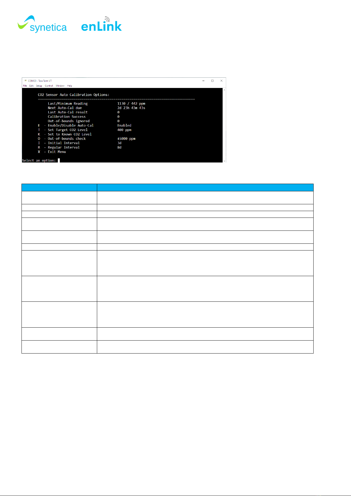
To view and set CO2sensor calibration information, enter c and the screen below will show.
Please see the table below for information on each menu item.
Menu Item
Description / details
Last/Minimum Reading
Shows the last CO2value read and the minimum CO2value read since the last auto
calibration.
Next Auto-Cal due
Shows when the next autocalibration routine will occur
Last Auto-Cal result
Shows the value of the last auto calibration result. Used internally by the sensor.
Calibration Success
This shows the total number of successful auto calibrations since the device was powered
up.
Out-of-bounds Ignored
Shows the number of times that auto calibration did not run due to the Out Of Bounds
setting.
E - Enable/Disable Auto-Cal
Enables or disables the auto calibration routine.
T - Set Target CO2 Level
This is the known CO2corresponding to the minimum value the sensor has read since
power-up or last calibration. It is normally 'fresh air' or the lowest level when the building is
unoccupied
overnight or at weekends. Typically, this is 400 ~ 450 ppm.
K - Set to Known CO2 Level
This will re-calibrate the zero point of the sensor to a known gas concentration. The sensor
should be placed in this gas concentration and allowed to stabilise.
This command runs in the background and will take 8 to 10 seconds to complete.
As an example, fresh air is typically around 400 ~ 450 ppm.
O - Out-of-bounds check
The Out-of-bounds value is used to ignore the calibration if the minimum value the sensor
has read is not within a sensible range of the target concentration level.
So, if the target concentration level is 400, the Out-of-bounds value is ±50 and the minimum
reading is 451 (or more), the calibration routine is ignored.
I - Initial Interval
It is possible for the first auto-calibration to take place more quickly than the regular auto-
calibration events. This can be useful to stabilise the readings quickly after installation.
R - Regular Interval
This is the standard calibration interval; it is set to 8 days by default to accommodate a week
long period where the minimum sensed CO2level should have fallen to background levels.
The CO2sensor needs to be exposed to fresh, clean air periodically for the auto calibration to be successful. Most
occupied areas are unoccupied for some time during a week-long period, typically at night, or at the weekend and therefore
the auto calibration runs every 8 days by default. Background CO2levels are typically around 400-450 ppm, if the
background CO2level is known to be a different value, then this can be set in the “Set Target CO2Level” parameter
If a unit is placed in an area where the CO2level may not fall below a certain level, e.g. 450ppm, during the calibration
interval then the “Out-of-bounds check” parameter can be set so that the auto calibration routine does not run. As an
example, if an area is continuously occupied for a long period and the minimum CO2reading does not fall below, say
450ppm, then it is undesirable to run the autocalibration routine based on a target of 400ppm. In this case, if the “Set
Target CO2 Level” is set to 400ppm and the “Out-of-bounds check” value is set to +/-50 ppm then the autocalibration
routine will not run unless the minimum read value falls below 451ppm in the interval.

SYNETICA enLink Zone Plus User Guide Rev 1.6
8. CO2Monitoring
Measuring CO2levels can serve as a good indicator of the indoor air quality. CO2concentrations within a building often
are used to indicate whether adequate fresh air is being supplied to the space. Indoor CO2concentration is directly
proportional to the number of people in a building and the ability of the ventilation system to dilute the CO2generated by
occupants.
Moderate to high levels of carbon dioxide can cause headaches and fatigue, and higher concentrations can produce
nausea, dizziness, and vomiting. Elevated levels of CO2can also affect performance and productivity. In one study3of 24
employees, cognitive scores were 50% lower when the participants were exposed to 1,400ppm of CO2compared with
550ppm during a working day.
CO2concentration
Remarks / Effect
400ppm
Normal CO2concentration in outdoor ambient air
400-1,000ppm
Concentrations typical of occupied indoor spaces with good ventilation
1,000-2,000ppm
Complaints of drowsiness and poor air.
2,000-5,000 ppm
Headaches, sleepiness and stagnant, stale, stuffy air.
Lack of concentration, loss of attention, increased heart rate and slight nausea may
also be present.
5,000ppm +
Workplace exposure limit (as 8-hour TWA)

SYNETICA enLink Zone Plus User Guide Rev 1.6
9. VOC Monitoring
In both indoor and outdoor environments, poor air quality can greatly impact our health and well-being. Volatile Organic
Compounds (VOC) concentration in an indoor space is a key indicator for air pollution measurement
Official air quality monitoring stations provide only consolidated or averaged data for the outdoor environment without
the corresponding indoor air data. They do not generate personalised information.
The Zone Plus unit incorporates a highly sensitive VOC sensor for air pollution measurement. Gases that can be detected
by the VOC sensor include: Volatile Organic Compounds (VOC) from paints (such as formaldehyde), lacquers, paint
strippers, cleaning supplies, furnishings, office equipment, glues, adhesives and alcohol.
The table below illustrates the IAQ Index level parameter with a description of the air quality, its impact and suggested
action for that level / banding. The unit also outputs a bVOC parameter which is the total VOC’s expressed as a parts per
million (PPM) value instead of an index (see section 13 below for more details).
IAQ Index
Air Quality
Impact (long-term exposure)
Suggested action
0 –50
Excellent
Pure air; best for wellbeing
No measures needed
51 –100
Good
No irritation or impact on wellbeing
No measures needed
101 –150
Lightly polluted
Reduction of wellbeing possible
Ventilation suggested
151 –200
Moderately polluted
More significant irritation possible
Increase ventilation with clean air
201 –2501
Heavily polluted
Exposition might lead to effects like
headache depending on type of VOC
Optimise ventilation
251 –350
Severely polluted
More severe health issue possible if
harmful VOC present
Contamination should be identified
if level is reached even without the
presence of people; maximise
ventilation and reduce attendance
> 351
Extremely polluted
Headaches, additional neurotoxic
effects possible
Contamination needs to be
identified; avoid presence in room
and maximise ventilation
Indoor air quality (IAQ) classification and colour coding 1
1
According to the guidelines issued by the German Federal Environmental Agency, exceeding 25 mg/m3of total VOC leads to headaches and further
neurotoxic impact on health.
Compliant to the ISO16000-29 standard “Test methods for VOC detectors”.

SYNETICA enLink Zone Plus User Guide Rev 1.6
10. PIR Sensor Operation
The PIR Sensor incorporated within some variants of the enLink Zone Plus can be used to indicate occupancy status
within an area.
The implementation incorporates two incrementing counters PIR_COUNT and PIR_OCC_TIME to represent the
occupied/unoccupied historical profile.
The PIR has a concept of an ‘inactivity timeout’. This is set to 30 seconds.
When the PIR detects movement (possibly multiple times) the internal occupancy state changes to the ‘occupied’ state.
If the PIR does not detect any movement for a period of 30 seconds the internal state changes to ‘unoccupied’ (see
diagram below).
The sensor has two LoRa wireless data parameters associated with the PIR operation:
•PIR_COUNT –the number of changes from the ‘unoccupied’ state to the ‘occupied’ state. This is reported in the
data packet as Type 0x13 (Detection Count)
•PIR_OCC_TIME –the total time period spent in the ‘occupied’ state in seconds. This is reported in the data packet
as Type 0x14 (Total Occupied Time).
Each counter is implemented as a 32 bit number so the maximum PIR_COUNT is 4,294,967,295 and the PIR_OCC_TIME
is over 49 thousand days. The counters are stored in non-volatile memory but can be reset via the configuration menu.

SYNETICA enLink Zone Plus User Guide Rev 1.6
PIR data transmission interval
Depending on the enLink Zone Plus settings the PIR_COUNT and PIR_OCC_TIME messages will be sent at a fixed time
interval or when the status changes (within constraints of the regulatory wireless duty cycle).
In some applications it is useful to receive a wireless notification when the PIR state changes without waiting for the
transmit interval. This is known as “Adaptive Transmission Interval”.
When set to a fixed time interval the unit will send a wireless message containing the PIR status at the set Transmit
Interval.
When set to “Adaptive” transmit interval the unit will send a wireless message containing the PIR status when the status
changes with the following constraints:
•The message will be transmitted immediately providing at least the time in the Adaptive Min Interval has passed.
So, for example if the Adaptive Min Interval is set to 5 mins then if the last message was sent 4 minutes ago
transmission will be delayed until the 5 minutes have passed. This prevents messages being sent more frequently
than the Adaptive Min interval setting.
•If the occupancy state does not change then a wireless message will be sent at the Adaptive Max Interval. This
in effect acts as a heartbeat message.
Please note that LoRa operates in unlicensed radio spectrum and therefore each device must obey regulatory duty cycle
regulations. If messages are sent too frequently then the device will delay transmission to comply with the duty cycle limits.
The transmission interval is configured from within the Quick Start menu of the Zone Plus unit (note that this setting is
only present in models incorporating the PIR). To configure the transmit interval, follow the steps below:
Remove the enLink Zone Plus board from its enclosure. Take care when removing the board from the front part
of the enclosure and only use the slots provided at the bottom of the board to gently lift the board up and out of
the enclosure.
Connect a micro-USB cable to the enLink unit. The device will attach to a COM port on your PC. Refer to section
4 for details on connecting to the USB menu.
From the Main Menu, enter Qto enter the Quick Start Menu.
Quick Start Settings Menu
Access the Transmit Interval setting by entering t.

SYNETICA enLink Zone Plus User Guide Rev 1.6
Transmit Interval settings
To select a fixed transmit interval select the required interval from the menu options.
To select Adaptive Transmit Interval select the Aoption and then change the settings for the Adaptive Min
interval and Adaptive Max interval as required.
With adaptive transmit interval set, when a change of PIR status occurs a wireless message is sent immediately,
however messages will not be sent more frequently than the Adaptive Min interval.
The Adaptive Max interval acts like a heartbeat, so if no change of PIR state occurs then a message is sent at
the Adaptive Max interval.
Press Enter when the key is correctly entered to return to the Quick Start Settings Menu.

SYNETICA enLink Zone Plus User Guide Rev 1.6
11. Battery Installation / Replacement
enLink Zone Plus devices use 4 x SAFT LS14500 or EVE ER14505 AA size 3.6 Volt Lithium Thionyl Chloride (Li-SOCl2)
batteries (non-rechargeable) or direct equivalent.
No other batteries are approved for use in the device.
Lithium Thionyl Chloride batteries have very high energy capacity and must be used and handled with care observing the
guidance below.
WARNING
Risk of death or serious injury from explosion or fire.
•Keep out of sight and reach of children.
•Fire, explosion and burn hazard - do not recharge, short circuit, crush, disassemble, incinerate.
•Due to the high terminal voltage (3.6V), they are not suitable as direct replacements for other battery technologies in the same can sizes.
•When not in use the Batteries must be stored in a non-Hazardous Area.
•Do not change batteries in an explosive gas atmosphere.
•When installing batteries, do not snag the battery terminal on the clip or the battery may be damaged. Do not apply excessive force.
•Do not drop. Dropping the battery may cause damage. If a battery is dropped, do not install the dropped battery into the unit. Dispose of dropped
battery promptly per local regulations or per the battery manufacturer’s recommendations.
Guidance
•Always install the batteries correctly as per instructions taking great care to observe the battery polarity.
•Ensure that the contact points are clean and conductive.
•All batteries must be the same model from the same manufacturer.
•Do not mix old and new batteries or batteries from different manufacturers.
•Do not heat or attempt to recharge the battery.
•Do not dispose of in a fire.
•Only install approved batteries: SAFT LS14500 or EVE ER14505 Lithium Thionyl Chloride AA Battery 3.6 Volt, or direct equivalent.
Safe disposal
•Please recycle responsibly, a wide range of schemes are available.
•Do not dispose of in normal waste or in a fire.

SYNETICA enLink Zone Plus User Guide Rev 1.6
12. External Power
The Zone Plus may be powered from an external power source if required. The unit requires 12 –24V DC at 250mA.
Power is supplied to the unit via a 2 pole Molex push button connector as shown below.
The conductor size should be 18-26 AWG (1mm –0.5mm diameter, 0.82mm CSA –0.13mm CSA). Strip the cable to
expose 5mm of conductor.
Zone Plus External Power Connector
Push the stripped end of the power cable into the connector taking great care to observe the correct polarity. The positive
cable should connect to the terminal marked (+) and the negative cable to the terminal marked (-)
Power Wire Insertion
Gently pull on the cable to ensure that that it is correctly inserted. Ensure that no uninsulated cable is showing.
Once complete, move the power switch to the EXT position for external power as shown below. The unit will power up
and attempt to join the LoRaWAN network.
Wire is directly inserted and pushes open
low-insertion force gate-style terminal, which
“traps” wire in place.
Wire strip length is 5mm
Cable Release
Button
Cable Entry Point

SYNETICA enLink Zone Plus User Guide Rev 1.6
Zone Plus power switch, select EXT position
To release the cable, gently press down on the button lever, as shown below and the cable will release freely.
Release Power Cables
Button-style lever is pushed
down, gate-style terminal
opens, and wire can be freely
pulled out.
BATT
EXT

SYNETICA enLink Zone Plus User Guide Rev 1.6
13. LoRaWAN Payload Decoder
The latest LoRaWAN payload decoders and guides are available on the Synetica GitHub repository:
https://github.com/synetica/enlink-decoder
A live payload decoder which allows you to paste LoRa payloads in Hexadecimal or Base 64 and see the correctly decoded
results can be found at the link below:
https://synetica.github.io/enlink-decoder/
14. Technical Support
For technical assistance, please visit the downloads section of our web site at www.synetica.net or email us at
Table of contents
Other Synetica Accessories manuals
Popular Accessories manuals by other brands

Ricoh
Ricoh DataOverwriteSecurity Unit Type A operating instructions

Goobay
Goobay 76778 user manual

Miller Electric
Miller Electric Coolmate Coolmate 4 Specifications

Emerson
Emerson Rosemount 222 Reference manual

SENSTAR
SENSTAR FiberPatrol FP1100X Series Site Planning & Installation Guide

Laird
Laird Sentrius BT610 user guide

Sartorius
Sartorius IS 64 FEG-S0CE Installation and operating instructions

YOKOGAWA
YOKOGAWA DO72 instruction manual

dtm
dtm Azymut Installation and operating manual

Johnson Controls
Johnson Controls WRZ-TTB0000-5 installation guide

PROformance Hoops
PROformance Hoops PROVIEW Series Installation & owner's instructions

Royal
Royal Lounge 260 instructions