Syntec 710CA User manual

710CA Laser Cutting Machine Assembly Manual
匯出日期:2024-01-30
修改日期:2023-12-31

自動化產品(繁體中文)
–
710CA Laser Cutting Machine Assembly Manual
–2
•
•
•
•
•
•
•
•
•
•
•
•
•
•
•
•
•
•
•
•
•
•
•
•
•
•
•
•
•
•
•
Subject
Basic Machine Setting
Hardware Introduction
Installation Process
Mechanical Installation
710CA Controller
FC DI/DO Module
Four-in-One Driver
ADDA
Capacitive Sensor Amplifier Module
Wiring
Overall Wiring
Driver Brake Wiring
Laser Source Wiring
Connection Settings
Controller Setting
PC Setting
ProCAM Setting
Troubleshooting Connection Issues
Parameter Setting
Axis Mechanism Parameters
Extended Parameters
Common Parameters
IO-Related Parameters
Driver Parameters
I/O Settings
Handheld Remote Controller IO Point Settings
IO Mapping Settings
O-Point Software Mapping Table
I-Point Software Mapping Table
序
號
版
本
號
編修日期 編修內容 議題連結 作者 審查 核準
1 V1.0 2023-
11-7
新增 710CA 雷射
切割配機手冊
AUTO-11225 @何
明穎
@
王
亦
恩
@
吳
冠
毅
中文版Mandarin Version: 710CA 雷射切割配機手冊
文件資訊 文件履歷
文件資訊 文件履歷

自動化產品(繁體中文)
–
710CA Laser Cutting Machine Assembly Manual
Subject–3
1 Subject
By following this manual, you can easily install your own laser cutting system.

自動化產品(繁體中文)
–
710CA Laser Cutting Machine Assembly Manual
Basic Machine Setting–4
2 Basic Machine Setting
The laser cutting system includes a controller, laser source, keyboard and mouse interface. This manual will guide
users through the installation process, starting with the mechanical setup, step by step.
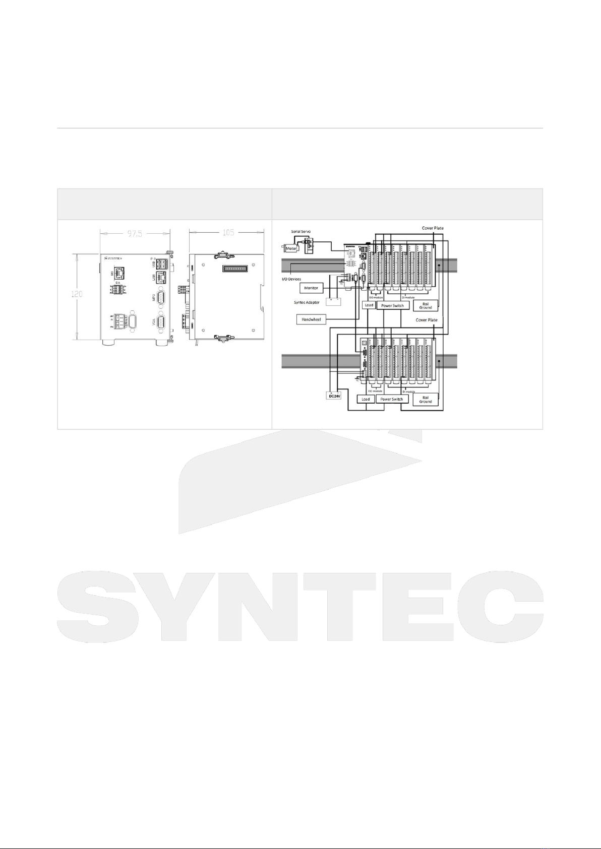
2.1 Hardware Introduction
710CA
Controller
24V Power
Adapter
Four-in-One
Driver
ADDA CapacitiveSensor
AmplifierModule
Motor Motor Power
Cable
Motor Encoder
Cable
M3
Communication
Cable
CapacitiveSensor
AmplifierModule
Communication Cable
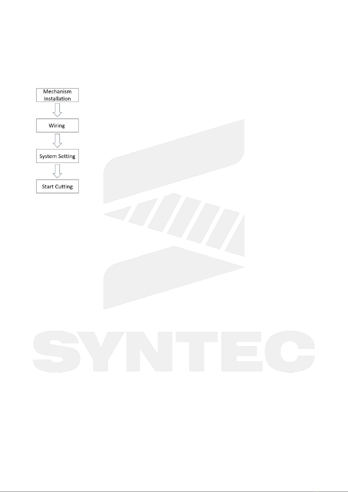
2.2 Installation Process
Mechanical Installation: Complete the installation of the mechanics, including motors, drivers, controller, and
laser source.
Wiring: Connect the wiring between the motors, drivers, controller, and laser source. Once this step is completed,
you can power up the system.

自動化產品(繁體中文)
–
710CA Laser Cutting Machine Assembly Manual
Basic Machine Setting–5
System Setting: This step involves software operations, includingparameter settings, I/O configurations. Once the
system is configured, you will be able to precisely control the laser cutting controller.
Start Cutting: After completing the system setup, you can operate the cutting system.

自動化產品(繁體中文)
–
710CA Laser Cutting Machine Assembly Manual
Mechanical Installation–6
3 Mechanical Installation
3.1 710CA Controller
The 710CA controller's external dimensions and peripheral product installation are as follows:
External Dimensions Peripheral Product Quick Installation Diagram
3.2 FC DI/DO Module
The FC DI/DO module's external dimensions and peripheral product installation are as follows:

自動化產品(繁體中文)
–
710CA Laser Cutting Machine Assembly Manual
Mechanical Installation–7
•
•
•
•
External Dimensions Peripheral Product Quick Installation Diagram
FC DO Module is PNP Interface
FC DI Module can be PNP or NPN Interface
PNP Interface: Connect COM to 24V
NPN Interface: Connect COM to 0V
3.3 Four-in-One Driver
The Four-in-One driver's external dimensions and peripheral product installation are as follows:

自動化產品(繁體中文)
–
710CA Laser Cutting Machine Assembly Manual
Mechanical Installation–8
External Dimensions Peripheral Product Quick Installation Diagram
3.4 ADDA
ADDA's external dimensions and installation method are as follows:

自動化產品(繁體中文)
–
710CA Laser Cutting Machine Assembly Manual
Mechanical Installation–9
•
•
External Dimensions ADDA Installation Diagram
Installation Steps
Remove the dust plug from the right side of the driver and align the
connector on the left side of the expansion card with the connector on
the right side of the driver (Figure 1).
Secure one long screw (nickel-plated round head screw 3*10) provided in
screw hole 1 and four short screws in screw holes 2 to 4 (Figure 2) to
complete the assembly.
3.5 CapacitiveSensor AmplifierModule
The CapacitiveSensor AmplifierModule's external dimensions and installation method are as follows:

自動化產品(繁體中文)
–
710CA Laser Cutting Machine Assembly Manual
Mechanical Installation–10
•
•
External Dimensions CapacitiveSensor AmplifierModule
Installation Diagram
Installation Steps
Connect one end of the
CapacitiveSensor AmplifierModule
Communication Cable to the ADDA ECN
and the other end to the
CapacitiveSensor AmplifierModule.
Use an RF cable to connect the
CapacitiveSensor AmplifierModule to
the cutting head.

自動化產品(繁體中文)
–
710CA Laser Cutting Machine Assembly Manual
Wiring–11
4 Wiring
4.1 Overall Wiring
Note: It is recommended to keep power cables and signal cables separate to avoid signal interference.
4.2 Driver Brake Wiring

自動化產品(繁體中文)
–
710CA Laser Cutting Machine Assembly Manual
Wiring–12
4.3 Laser Source Wiring

自動化產品(繁體中文)
–
710CA Laser Cutting Machine Assembly Manual
Connection Settings–13
5 Connection Settings
5.1 Controller Setting
STEP 1: Ensure that the ethernet cableis connected to the computer.
STEP 2: On the main screen, press F5 for "Electrical Module", then press F1 for "Maintain", and then press F2 for
"Set Kernel Server". Enter the controller's IP address and subnet mask, such as IP address: 192.168.1.200, subnet
mask: 255.255.255.0.
STEP 3: On the network settings screen, press F5 for "Set Kernal Server". Choose "Open" for the "Start server
while boot" option and set the timeout to <30000> (in milliseconds).

自動化產品(繁體中文)
–
710CA Laser Cutting Machine Assembly Manual
Connection Settings–14
STEP 4: After configuring, press F1 to "Start Server", and then press F3 for "OK".
STEP 5: You will return to the network settings screen. Press F1 for "Save Setting" to complete the setup.
STEP 6: Restart the system.
5.2 PC Setting
STEP 1: Connect your computer to the controller using an ethernet cable.
STEP 2: Configure the IP address on your computer, for example: 192.168.1._. The last digit should be different from
the controller's IP.

自動化產品(繁體中文)
–
710CA Laser Cutting Machine Assembly Manual
Connection Settings–15
5.3 ProCAM Setting
STEP 1: Open ProCAM.
STEP 2: Configure the ProCAM connection settings.
STEP 3: Restart ProCAM.

自動化產品(繁體中文)
–
710CA Laser Cutting Machine Assembly Manual
Connection Settings–16
•
•
•
•
•
5.4 Troubleshooting Connection Issues
Controller
Verify if the kernel server is running.
PC
Use Command Prompt to check if you can ping the controller's IP and port (e.g., if the controller's IP is
192.168.1.200, enter "ping 192.168.1.200" in Command Prompt).
If you receive a response, it means your computer can connect to the controller. Restart the controller.
If it shows "Destination host unreachable. Request timed out", check if your computer's IP settings are on
the same network as the controller.
Other:
If all the above steps have been confirmed and you are still having issues, consider changing the IP settings
for either the controller or the computer to be on a different subnet. For example, if the controller's IP is
192.168.1.200, set the computer's IP to 192.168.1.150.

自動化產品(繁體中文)
–
710CA Laser Cutting Machine Assembly Manual
Parameter Setting–17
•
•
•
•
•
•
•
6 Parameter Setting
6.1 AxisMechanism Parameters
Para
meter
s
Item Setti
ng
Value
Description
Pr9 *Servo board
type
Depe
nd on
site
103: M3 Serial
110: EtherCAT Serial
Pr21~
Pr40
*Axis
corresponding
axis card port
number
Depe
nd on
site
When using a single-axis drive, this parameter is set to MM,
representing the corresponding drive station number (MM=022).
When using a multi-axis drive, this parameter is set as MMnnn,
with the following meanings:
MM : Main station number(1~16), refer to the instructions for
drive DIP switch settings in the notes.
nnn: Sub-station number (000~010).
Pr41~
P60
Axial motor
polarity
Depe
nd on
site
This parameter allows you to set the actual motion direction for
each axis of the machine:
0:No reversal
1:Reversal
Pr61~
Pr68
Axial encoder
resolution
Depe
nd on
site
Syntec's motor:4194304
Pr81~
Pr100
Axial encoder
scaling factor
Depe
nd on
site
Syntec's motor:4
Pr121
~Pr16
0
Axial screw side
gear number/
motor side gear
number
Depe
nd on
site
This parameter sets the gear ratio between the screw side and
the motor side in the mechanical structure to allow the system
to determine the speed ratio between the motor and the screw.
Number of gear tooth on screw side: Number of gear tooth on
motor side = 2:1 →Motor speed: Screw speed = 2:1.
Pr161
~Pr18
0
Axial pitch
amount (Pitch)
Depe
nd on
site
This parameter is used to set the linear feed amount for one
revolution of a lead screw.
If it's a rotary axis, this parameter represents the feed amount
for one revolution of the rotary axis.

自動化產品(繁體中文)
–
710CA Laser Cutting Machine Assembly Manual
Parameter Setting–18
•
•
•
•
•
•
•
•
Para
meter
s
Item Setti
ng
Value
Description
Pr201
~Pr22
0
Axis sensor type Depe
nd on
site
0: General encoder (relative encoder).
1: Optical scale.
2: No feedback.
3: Absolute encoder.
4: Single-turn absolute encoder.
If you are using a Syntec's motor with an absolute encoder, set it to 3.
For other encoder types, configure them according to the specific
encoder used.
Pr221
~Pr24
0
Axial type Depe
nd on
site
0:Linear axis type
1~5:Rotary axis types A-E
For a list of rotary axis types, please refer to the Parameter Manual.
Pr321
~Pr34
0
Axis name Depe
nd on
site
Pr321:100
Pr322:200
Pr323:1003
Pr324:201
Pr382
1~P38
22
*Coupling master
and slave axis
number
Depe
nd on
site
Pr3821 and Pr3822 are used to set the corresponding axis
numbers for two axes moving together in master and slave
relationships.
For example, when Pr3821 is set to 1 (representing the X-axis)
and Pr3822 is set to 2 (representing the Y-axis), the Y-axis will
follow the movement of the X-axis, and the movement ratio will
change based on the settings in Pr3823 and Pr3824.
Pr382
3~P38
24
*Coupling master
and slave axis
ratio factor
Depe
nd on
site
Pr3823 and Pr3824 are used to set the synchronous ratio for two
axes moving together in a synchronized manner.
For example, when Pr3823 is set to 1 and Pr3824 is set to 2, when
the master axis moves 1mm, the slave axis will move 2mm.
Pr382
5
*Coupling type Depe
nd on
site
For double-column machine configurations (setting 2 - Equally
synchronous coupling).
In other cases, adjustments should be made based on the site.

自動化產品(繁體中文)
–
710CA Laser Cutting Machine Assembly Manual
Parameter Setting–19
•
•
•
6.2 ExtendedParameters
Parameters Item Setting Value Description
Pr3401 Max. voltage output of
laser(mV)
Depend on site
Pr3402 Arc cutting reference
speed(mm/min)
Depend on site Reference value: 8500
Pr3403 Laser Type Depend on site 0: Raycus, 1: Max Photonics, 5: IPG
YLM, 51: IPG YLR, 7: SwiRoc, 10: YAG
Pr3404 Communication Type Depend on site When using ADDA, set it to 0
(M3).
When using the FC module,
set it to 1 (SRI).
When using the Four-in-One
controller, set it to 2 (Four-in-
One).
Pr3406 *Pressure calibration curve
order
Depend on site 1: first order, 2: second order, 3: third
order
Pr3407 Default speed of cutter
moving down(mm/min)
Depend on site It is recommended not to exceed the
maximum speed of the Z-axis.
Pr3408 Shift speed(mm/min) Depend on site
Pr3409 Frogleap starting
height(mm)
Depend on site
Pr3410 *The maximum DA output
voltage
Depend on site 0: 0~10 V, 1: 0~5 V
Pr3411 Height Sensing Device Depend on site 0: Syntec's capacitor amplifier, 1:
LVDT

自動化產品(繁體中文)
–
710CA Laser Cutting Machine Assembly Manual
Parameter Setting–20
•
•
Parameters Item Setting Value Description
Pr3412 Non-capacitance sensor
touch workpiece value
Depend on site When the height sensor uses
a capacitor amplifier, set it to
0.
When the height sensor uses
a non-capacitor solution, set
it according to the on-site
conditions.
Pr3414 Height following sensitivity Depend on site 1: Weakest, 10: Strongest
Pr3415 Axis Over Travel NC/NO Depend on site 0: NO, 1: NC
Pr3417 Switch platform inner
position
Depend on site
Pr3418 Switch platform outer
position
Depend on site
Pr3419 Simulation coord. sys. Depend on site 0: XYZ, 1: XY, 2: YZ, 3: ZX, 4: YX, 5: YZ,
6: XZ
Pr3420 Auto focus function of
cutting head
Depend on site 0: Close, 1: Serial Axis, 2: Precitec DA,
3: Raytools DA
Pr3421 Switch platform enable Depend on site 1: Enable, 0: Disable
Pr3422 Tracking device Depend on site 0: Driver, communication type
Pr3404 should be set to 0. If it does
not match, an alarm will occur.
1: Four-in-one controller,
communication type Pr3404 should
be set to 2. If it does not match, an
alarm will occur.
2: HYD, communication type Pr3404
cannot be set to 0. If it does not
match, an alarm will occur.
Table of contents
Other Syntec Cutter manuals
Popular Cutter manuals by other brands

KONWA
KONWA KW-123L Instruction manual & parts list

Rustic Woodworking
Rustic Woodworking E-Z Series product manual

Hitachi
Hitachi CM12Y Handling instructions

Weber Rescue Systems
Weber Rescue Systems SPS 270 MK2 E-FORCE3 operating manual

Sandrigarden
Sandrigarden SG-TR 20 instruction manual

Far Tools
Far Tools TCS 200 Original manual translation