Syntec 720CA User manual

720CA Laser Cutting Machine Assembly Manual -
Pulse Driver
匯出日期:2023-12-25
修改日期:2023-12-24

自動化產品(繁體中文)
–
720CA Laser Cutting Machine Assembly Manual - Pulse Driver
–2
•
•
•
•
•
•
•
•
•
•
•
•
•
•
•
•
•
•
•
•
•
•
•
•
Subject
Basic Machine Configuration
Hardware Introduction
Installation Process
Mechanical Installation
720CA Controller
Serial Driver
Capacitive Sensor Amplifier Module
Wiring
Overall Wiring
Z-Axis Encoder Wiring
Capacitive amplifier Wiring
Laser Source Wiring
Parameter Setting
Axis Mechanism Parameters
Extended Parameters
Common Parameters
IO-Related Parameters
I/O Settings
Handheld Remote Controller IO Point Settings
IO Mapping Settings
O-Point Software Mapping Table
I-Point Software Mapping Table
序
號
版
本
號
編修日期 編修內容 議題連結 作者 審查 核準
1 V1.0 2023-
11-7
新增 720CA 雷射
切割配機手冊 - Z
軸泛用型
AUTO-11225 @何
明穎
@
王
亦
恩
@
吳
冠
毅
中文版Mandarin Version: 720CA 雷射切割配機手冊 - Z軸泛用型
文件資訊 文件履歷
文件資訊 文件履歷

自動化產品(繁體中文)
–
720CA Laser Cutting Machine Assembly Manual - Pulse Driver
Subject–3
1 Subject
By following this manual, you can easily install your own laser cutting system.

自動化產品(繁體中文)
–
720CA Laser Cutting Machine Assembly Manual - Pulse Driver
Basic Machine Configuration–4
2 Basic Machine Configuration
The laser cutting system includes a controller, laser source, keyboard and mouse interface. This manual will guide
users through the installation process, starting with the mechanical setup, step by step.
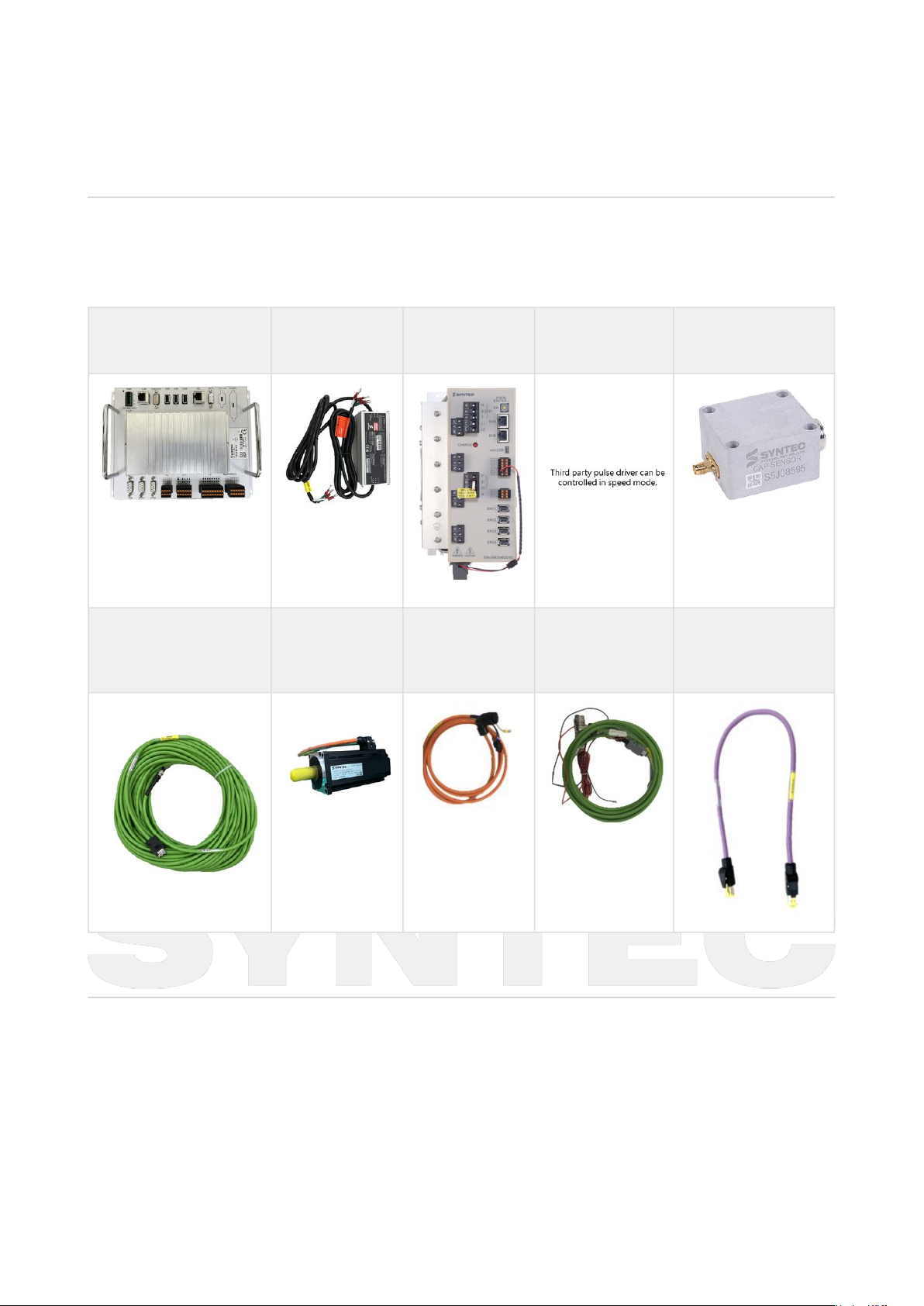
2.1 Hardware Introduction
720CA Controller 24V Power
Adapter
Serial Driver Pulse Driver Capacitive Sensor
Amplifier Module
Capacitive Sensor
Amplifier Module
Communication Cable
Motor Motor Power
Cable
Motor Encoder
Cable
M3 Communication
Cable
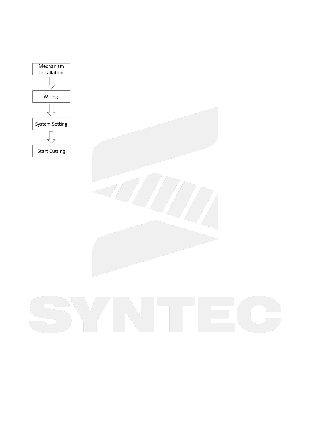
2.2 Installation Process
Mechanical Installation: Complete the installation of the mechanics, including motors, drivers, controller, and
laser source.
Wiring: Connect the wiring between the motors, drivers, controller, and laser source. Once this step is completed,
you can power up the system.
System Setting: This step involves software operations, including parameter settings, I/O configurations. Once the
system is configured, you will be able to precisely control the laser cutting controller.

自動化產品(繁體中文)
–
720CA Laser Cutting Machine Assembly Manual - Pulse Driver
Basic Machine Configuration–5
Start Cutting: After completing the system setup, you can operate the cutting system.

自動化產品(繁體中文)
–
720CA Laser Cutting Machine Assembly Manual - Pulse Driver
Mechanical Installation–6
3 Mechanical Installation
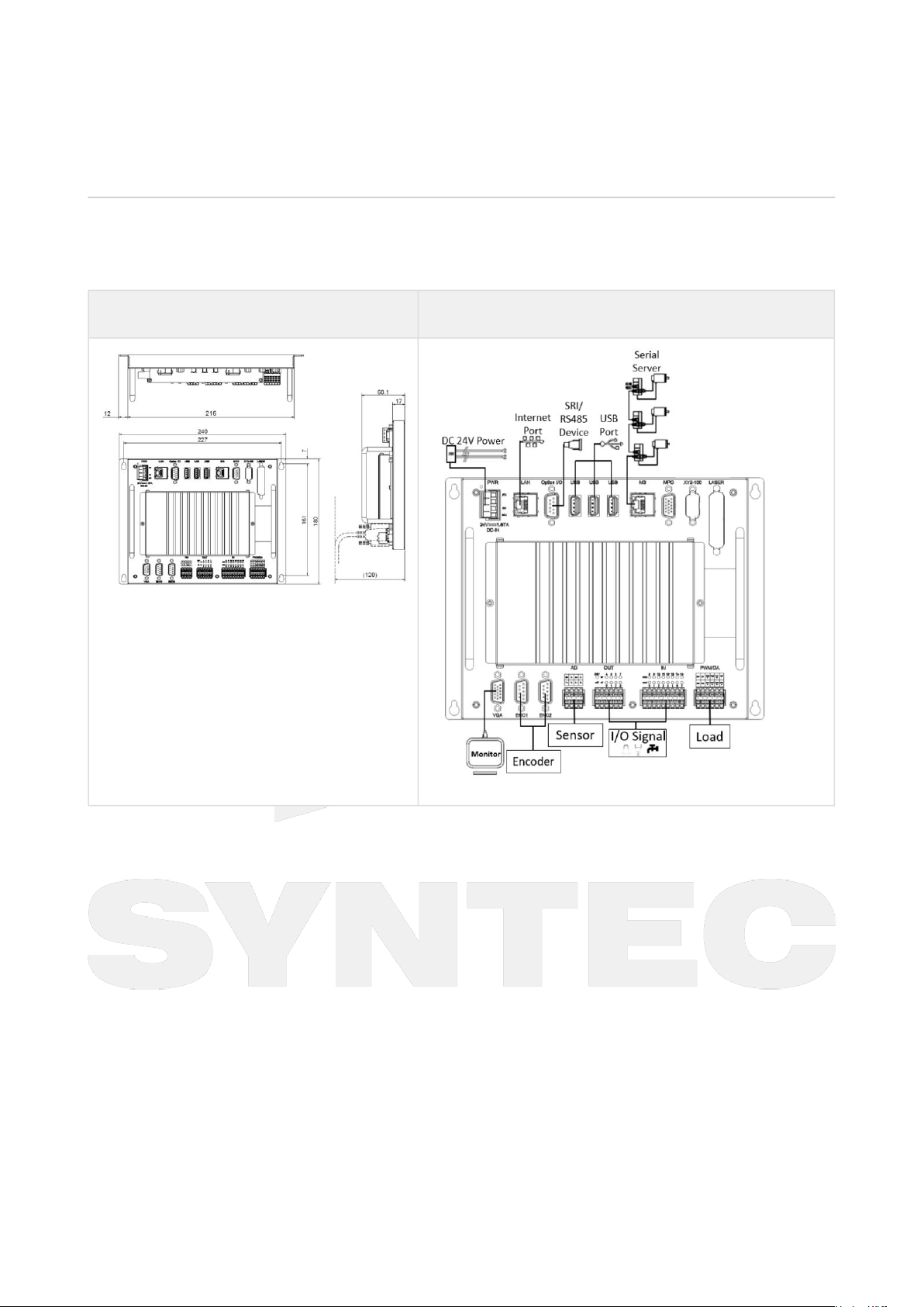
3.1 720CA Controller
The 720CA controller's external dimensions and peripheral product installation are as follows:
External Dimensions Peripheral Product Quick Installation Diagram
3.2 Serial Driver
The serial driver's external dimensions and peripheral product installation are as follows:

自動化產品(繁體中文)
–
720CA Laser Cutting Machine Assembly Manual - Pulse Driver
Mechanical Installation–7
External Dimensions Peripheral Product Quick Installation Diagram
3.3 Capacitive Sensor Amplifier Module
The Capacitive Sensor Amplifier Module's external dimensions and installation method are as follows:
External Dimensions Capacitive Sensor Amplifier Module Installation Diagram

自動化產品(繁體中文)
–
720CA Laser Cutting Machine Assembly Manual - Pulse Driver
Wiring–8
4 Wiring
4.1 Overall Wiring
Note: It is recommended to keep power cables and signal cables separate to avoid signal interference.
4.2 Z-Axis Encoder Wiring

自動化產品(繁體中文)
–
720CA Laser Cutting Machine Assembly Manual - Pulse Driver
Wiring–9
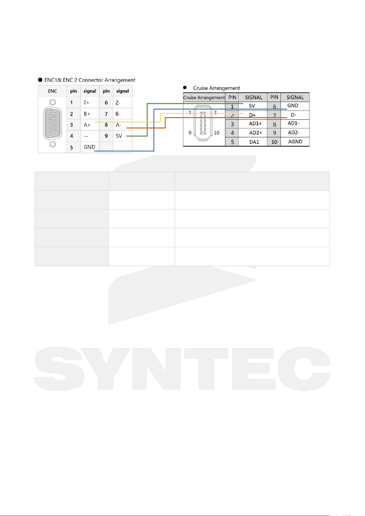
4.3 Capacitive amplifier Wiring
Pinout table for ENC and height adjustment connector
ENCPin Height adjustment connector
1A+ D+
2A- A-
35V 5V
4GND GND

自動化產品(繁體中文)
–
720CA Laser Cutting Machine Assembly Manual - Pulse Driver
Wiring–10
4.4 Laser Source Wiring

自動化產品(繁體中文)
–
720CA Laser Cutting Machine Assembly Manual - Pulse Driver
Parameter Setting–11
•
•
•
•
•
•
•
5 Parameter Setting
5.1 Axis Mechanism Parameters
Para
meter
s
Item Setti
ng
Value
Description
Pr9 *Servo board
type
Depe
nd on
site
103: M3 Serial
110: EtherCAT Serial
Pr21~
Pr40
*Axis
corresponding
axis card port
number
Depe
nd on
site
When using a single-axis drive, this parameter is set to MM,
representing the corresponding drive station number (MM=022).
When using a multi-axis drive, this parameter is set as MMnnn,
with the following meanings:
MM : Main station number(1~16), refer to the instructions for
drive DIP switch settings in the notes.
nnn: Sub-station number (000~010).
Pr41~
P60
Axial motor
polarity
Depe
nd on
site
This parameter allows you to set the actual motion direction for
each axis of the machine:
0:No reversal
1:Reversal
Pr61~
Pr68
Axis encoder
resolution
Depe
nd on
site
Syntec's motor:4194304
Pr81~
Pr100
Axial encoder
scaling factor
Depe
nd on
site
Syntec's motor:4
Pr121
~Pr16
0
Axial screw side
gear number/
motor side gear
number
Depe
nd on
site
This parameter sets the gear ratio between the screw side and
the motor side in the mechanical structure to allow the system
to determine the speed ratio between the motor and the screw.
Number of gear tooth on screw side: Number of gear tooth on
motor side = 2:1 →Motor speed: Screw speed = 2:1.
Pr161
~Pr18
0
Axial pitch
amount (Pitch)
Depe
nd on
site
This parameter is used to set the linear feed amount for one
revolution of a lead screw.
If it's a rotary axis, this parameter represents the feed amount
for one revolution of the rotary axis.

自動化產品(繁體中文)
–
720CA Laser Cutting Machine Assembly Manual - Pulse Driver
Parameter Setting–12
•
•
•
•
•
•
•
•
Para
meter
s
Item Setti
ng
Value
Description
Pr201
~Pr22
0
Axis sensor type Depe
nd on
site
0: General encoder (relative encoder).
1: Optical scale.
2: No feedback.
3: Absolute encoder.
4: Single-turn absolute encoder.
If you are using a Syntec's motor with an absolute encoder, set it to 3.
For other encoder types, configure them according to the specific
encoder used.
Pr221
~Pr24
0
Axial type Depe
nd on
site
0:Linear axis type
1~5:Rotary axis types A-E
For a list of rotary axis types, please refer to the Parameter Manual.
Pr321
~Pr34
0
Axis name Depe
nd on
site
Pr321:100
Pr322:200
Pr323:1003
Pr324:201
Pr382
1~P38
22
*Coupling master
and slave axis
number
Depe
nd on
site
Pr3821 and Pr3822 are used to set the corresponding axis
numbers for two axes moving together in master and slave
relationships.
For example, when Pr3821 is set to 1 (representing the X-axis)
and Pr3822 is set to 2 (representing the Y-axis), the Y-axis will
follow the movement of the X-axis, and the movement ratio will
change based on the settings in Pr3823 and Pr3824.
Pr382
3~P38
24
*Coupling master
and slave axis
ratio factor
Depe
nd on
site
Pr3823 and Pr3824 are used to set the synchronous ratio for two
axes moving together in a synchronized manner.
For example, when Pr3823 is set to 1 and Pr3824 is set to 2, when
the master axis moves 1mm, the slave axis will move 2mm.
Pr382
5
*Coupling type Depe
nd on
site
For double-column machine configurations (setting 2 - Equally
synchronous coupling).
In other cases, adjustments should be made based on the site.

自動化產品(繁體中文)
–
720CA Laser Cutting Machine Assembly Manual - Pulse Driver
Parameter Setting–13
•
•
5.2 Extended Parameters
Parameters Item Setting Value Description
Pr3401 Max. voltage output of
laser(mV)
Depend on site
Pr3402 Arc cutting reference
speed(mm/min)
Depend on site Reference value: 8500
Pr3403 Laser Type Depend on site 0: Raycus, 1: Max Photonics, 5: IPG
YLM, 51: IPG YLR, 7: SwiRoc, 10: YAG
Pr3404 Communication Type Depend on site 0:M3,1:SRI,2:Four-in-One
Pr3406 *Pressure calibration curve
order
Depend on site 1: first order, 2: second order, 3: third
order
Pr3407 Default speed of cutter
moving down(mm/min)
Depend on site It is recommended not to exceed the
maximum speed of the Z-axis.
Pr3408 Shift speed(mm/min) Depend on site
Pr3409 Frogleap starting
height(mm)
Depend on site
Pr3410 *The maximum DA output
voltage
Depend on site 0: 0~10 V, 1: 0~5 V
Pr3411 Height Sensing Device Depend on site 0: Syntec's capacitor amplifier, 1:
LVDT
Pr3412 Non-capacitance sensor
touch workpiece value
Depend on site When the height sensor uses
a capacitor amplifier, set it to
0.
When the height sensor uses
a non-capacitor solution, set
it according to the on-site
conditions.
Pr3414 Height following sensitivity Depend on site 1: Weakest, 10: Strongest

自動化產品(繁體中文)
–
720CA Laser Cutting Machine Assembly Manual - Pulse Driver
Parameter Setting–14
Parameters Item Setting Value Description
Pr3415 Axis Over Travel NC/NO Depend on site 0: NO, 1: NC
Pr3417 Switch platform inner
position
Depend on site
Pr3418 Switch platform outer
position
Depend on site
Pr3419 Simulation coord. sys. Depend on site 0: XYZ, 1: XY, 2: YZ, 3: ZX, 4: YX, 5: YZ,
6: XZ
Pr3420 Auto focus function of
cutting head
Depend on site 0: Close, 1: Serial Axis, 2: Precitec DA,
3: Raytools DA
Pr3421 Switch platform enable Depend on site 1: Enable, 0: Disable
Pr3422 Tracking device Depend on site 0: Driver, communication type
Pr3404 should be set to 0. If it does
not match, an alarm will occur.
1: Four-in-one controller,
communication type Pr3404 should
be set to 2. If it does not match, an
alarm will occur.
2: HYD, communication type Pr3404
cannot be set to 0. If it does not
match, an alarm will occur.
5.3 Common Parameters
Parameters Item Setting Value
Pr3249 *MLC Alarm ID Expansion 32
Pr3804 Part count M code 88
Pr3813 *Number of extended global variables 20000
Pr3851 Tool break handle program No. 999900

自動化產品(繁體中文)
–
720CA Laser Cutting Machine Assembly Manual - Pulse Driver
Parameter Setting–15
•
•
•
Parameters Item Setting Value
Pr3701 *G code Macro call registry -1
Pr3702 *G code Macro call registry 1
Pr3703 *G code Macro call registry 2
Pr3704 *G code Macro call registry 3
Pr3705 *G code Macro call registry 11
5.4 IO-Related Parameters
Parameters Item Setting Value Description
Pr5 *I/O type Depend on site When using a custom IO
mapping table, please set
it to 100.
Pr3271 *Enables SRI in IO mapping
table
(0: Disable 1: Enable)
Depend on site Set to 0 when not using the
FC DI/DO module.
Set to 1 when using the FC
DI/DO module.

自動化產品(繁體中文)
–
720CA Laser Cutting Machine Assembly Manual - Pulse Driver
I/O Settings–16
6 I/O Settings
6.1 Handheld Remote Controller IO Point Settings
STEP 1: Connect the Handheld Remote Controller to the controller while the power is off, then restart the controller.
STEP 2: On the main screen, press F5 for "Electronic Module", then press F2 for "Parameter", press F10 ">>", and
then press F4 "I/O Mapping Table" to enter the I/O Mapping Table screen.
STEP 3: Press F5 "I/O Mapping Table" and find RF-HBB in the I/O Mapping Table screen. Set the start No. I to 480,
start No. O with a length of 15 to 480 , and starting O with a length of 1 to 499.
Note: If you cannot find RF-HBB in the I/O Mapping Table screen, press F5 "Default I/O Setting" to rescan the
hardware.
STEP 4: Restart the controller.
6.2 IO Mapping Settings
STEP 1: On the main screen, press F8 for "Machine Maker", then press F3 for "Set Single I/O", and then press F3
for "SRI".
STEP 2: After entering the Single-Point IO Settings screen, press F8 "Switch Mode" to enter the Single-Point IO
Settings editing mode.
STEP 3: Set the hardware IO points to correspond to the controller's software IO points. If set to -1, it indicates that
the point is disabled.

自動化產品(繁體中文)
–
720CA Laser Cutting Machine Assembly Manual - Pulse Driver
I/O Settings–17
STEP 4: Restart the controller.
6.3 O-Point Software Mapping Table
O Point Function Description
Laser Control Module
Non-SwiRoc laser source(Pr3403≠7)
O2 Enable the laser source
O3 YAG Layer 1
O4 YAG Layer 2
O5 YAG Layer 3
O6 YAG Layer 4
SwiRoc Laser Source(Pr3403=7)

自動化產品(繁體中文)
–
720CA Laser Cutting Machine Assembly Manual - Pulse Driver
I/O Settings–18
O Point Function Description
Laser Control Module
Non-SwiRoc laser source(Pr3403≠7)
O2 Request control
O3 Turn on the power supply
O4 Activate laser output
O5 Initiate system reset
Gas Control Module
O0 No. 1 air blow switch Auxiliary gas solenoid valve O-point.
O8 No. 2 air blow switch Auxiliary gas solenoid valve O-point.
O9 No. 3 air blow switch Auxiliary gas solenoid valve O-point.
Auto Focus Module (O13~O15)
O13 Z1 focus enable
O14 Z1 emergency stop
O15 Z1 home search
External Devices (O21~O28)
O21 Oil injection start
O22 Dust collection for the first
section
O23 Dust collection for the second
section

自動化產品(繁體中文)
–
720CA Laser Cutting Machine Assembly Manual - Pulse Driver
I/O Settings–19
O Point Function Description
Laser Control Module
Non-SwiRoc laser source(Pr3403≠7)
O24 Dust collection for the third
section
O25 Dust collection for the forth
section
O26 Dust collector switch
O27 Pressure relief during
processing
O28 Chiller (cooling machine)
switch
Hardware Panel (O55~O58)
O55 Start processing indicator Correspond to I55.
O56 Stop indicator Correspond to I56.
O58 Laser test indicator Correspond to I58.
Handheld Remote Controller (O480~O495)
O480 Start
O481 Stop Reset
O482 Reset
O483 Dry Run
O484 Frame
O485 Set OriginJog

自動化產品(繁體中文)
–
720CA Laser Cutting Machine Assembly Manual - Pulse Driver
I/O Settings–20
O Point Function Description
Laser Control Module
Non-SwiRoc laser source(Pr3403≠7)
O486 Laser Protection
O487 Laser Test
O488 Red light Break Point Position
O498 Seek Edge
O490 Cruise Switch
O491 Blow Gas
O492 Backward
O493 Return Zero
O494 Forward
O495 Rapid
6.4 I-Point Software Mapping Table
I Point Function Description
Hardware Travel Limits (I1~I8)
I1 First axis positive hardware limit
I2 First axis negative hardware limit
I3 Second axis positive hardware limit
I4 Second axis negative hardware limit
Table of contents
Other Syntec Cutter manuals