联达产品/LEANTEC Products
–
R41-LXC100-917Y Product Manual
•
•
•
•
•
•
•
•
•
•
•
•
•
•
•
•
•
•
•
•
•
•
•
•
•
Operator
Technician
Warranty
The robot and its optional components are delivered after the company's strict quality
control, testing and inspection, and the performance is confirmed to meet the
company's standards.
Within the warranty period of the delivered products, the company will only repair the
faults that occurred during normal use for free. (Please consult a salesperson in your
area for the warranty period.)
However, the customer will be charged for repairs (even within the warranty period) if:
1. Damage or failure caused by improper use and improper use of the manual.
2. Failure caused by the customer's unauthorized disassembly.
3. Damage caused by improper adjustment or unauthorized repair.
4. Damage caused by natural disasters such as earthquake and flood.
Warning
1.If the use of robots or related equipment exceeds the conditions of use and product
specifications described in this manual, the warranty will be invalid.
2. The Company shall not be liable for any fault or accident, or even personal injury or
death caused by the use of the products.
3. The Company cannot foresee all possible risks and consequences. Therefore, this
manual cannot warn the user of all possible risks.
1 Safety
1.1 About this chapter
1.2 Safety term
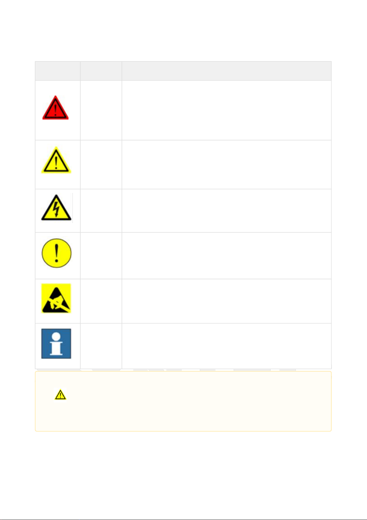
1.2.1 Safety Logo
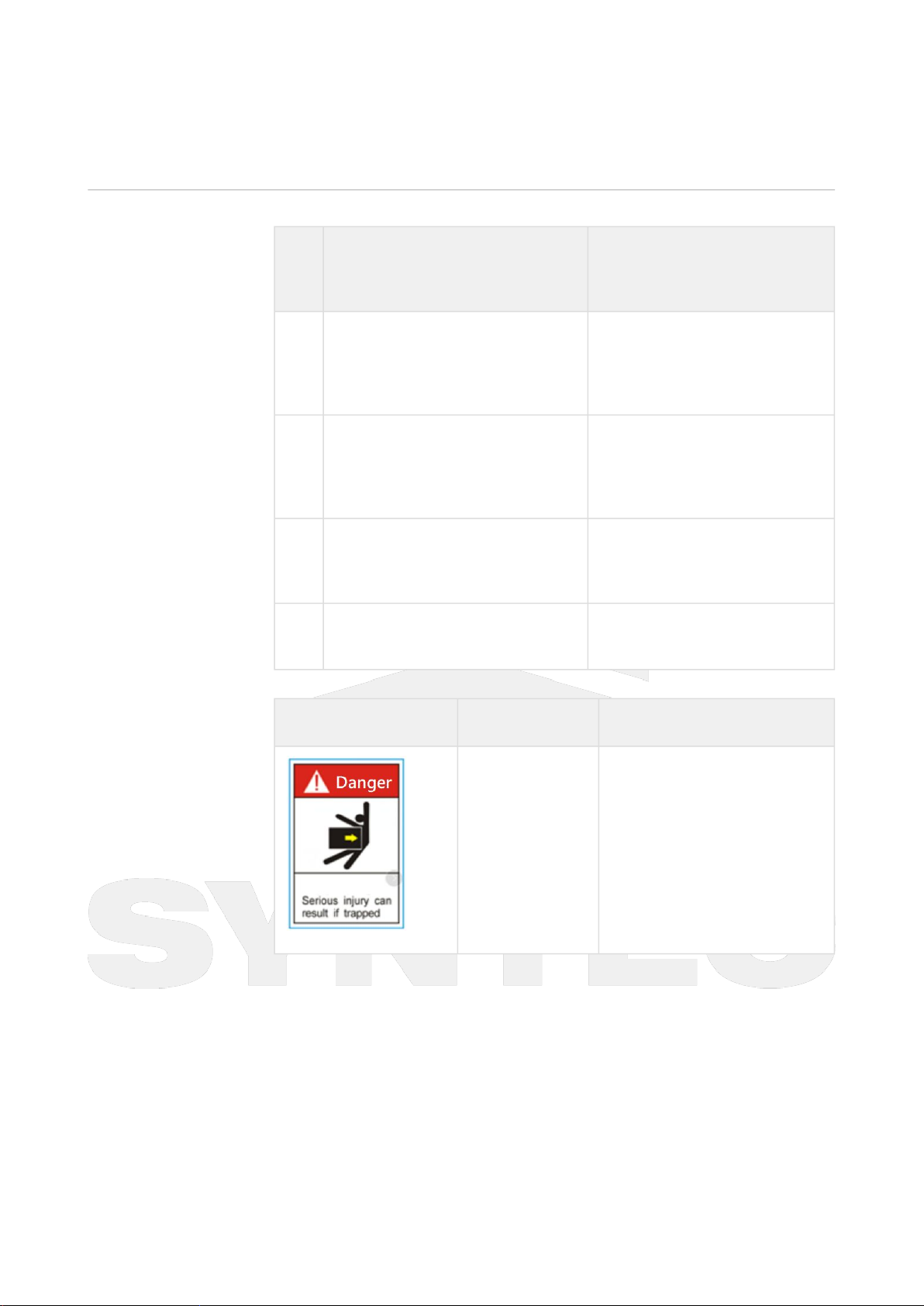
1.2.2 Risk Reminder
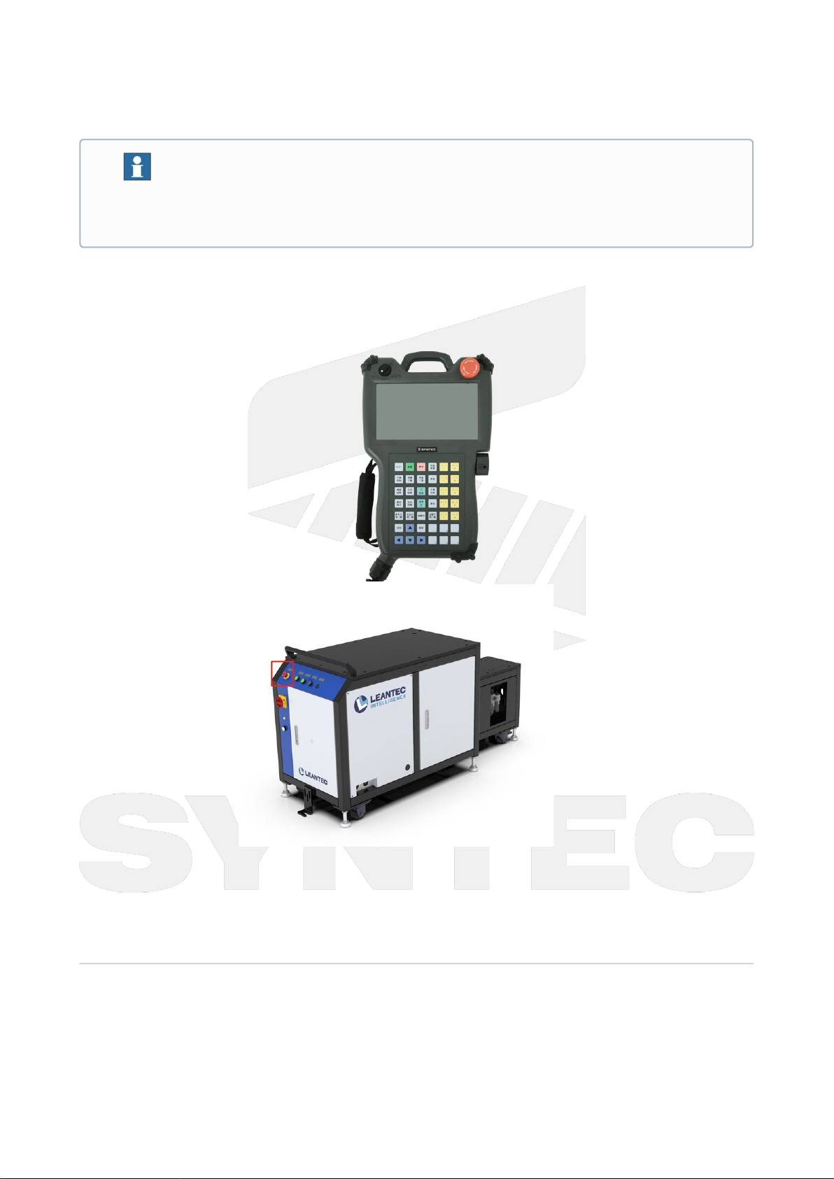
1.2.3 Emergency Stop
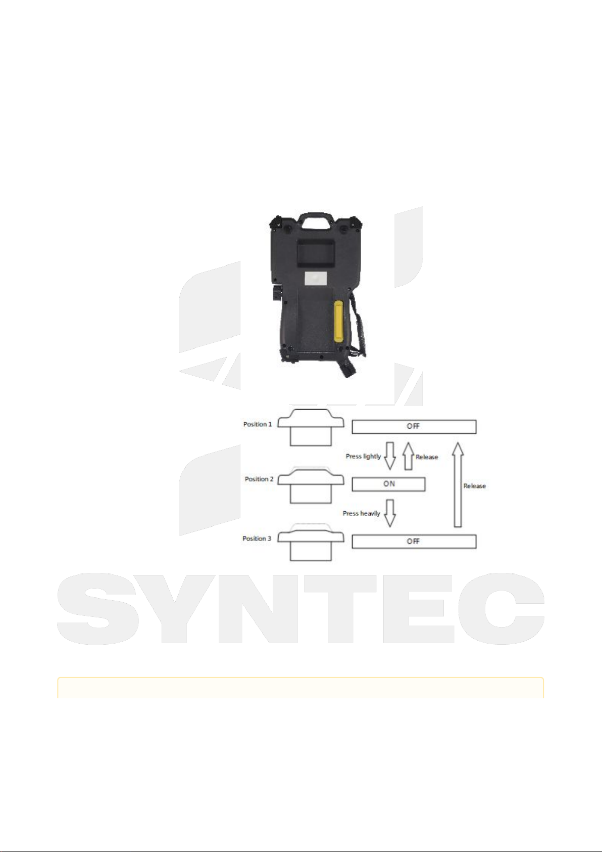
1.2.4 Enabling Switch
1.3 Work Safety Guide
1.3.1 Overview
1.3.2 Self Safety
1.3.3 Operate the teach pendant
1.3.4 Recover from Emergency Stop
1.3.5 Safety Considerations for Manual/Auto Mode
2 Double-Layer Trolley Robot Product Overview
2.1 Product Highlights
2.2 Product Operation Description
2.2.1 Precautions before operation
2.2.2 Operation Description
2.2.3 Alarm Description
2.3 Plate Setting Screen Description
3 Communication
3.1 Communication Description
3.2 NETPLC communication