SYR HF 3425 compact User manual

Bedienungsanleitung
Instruction manual
HF 3425 compact

2
Inhaltsverzeichnis
Table of contents
DE
EN
Inhaltsverzeichnis ......................................................................................................................................... 2
1. Verwendungsbereich ......................................................................................................................................... 3
2. Übersicht ......................................................................................................................................... 3
3. Einbau ......................................................................................................................................... 3
4. Rückspülung, Wartung ......................................................................................................................................... 3
5. Demontage ......................................................................................................................................... 5
6. Technische Daten ......................................................................................................................................... 6
7. Abmessungen ......................................................................................................................................... 7
8. Ersatzteile ......................................................................................................................................... 8
9. Zubehör ......................................................................................................................................... 9
Table of contents ......................................................................................................................................... 2
1. Range of use ....................................................................................................................................... 10
2. Overview ....................................................................................................................................... 10
3. Installation ....................................................................................................................................... 10
4. Backwashing, maintenance ....................................................................................................................................... 10
5. Disassembly ....................................................................................................................................... 12
6. Technical data ....................................................................................................................................... 13
7. Dimensions ....................................................................................................................................... 14
8. Spare parts ....................................................................................................................................... 15
9. Accessories ....................................................................................................................................... 16

3
1. Verwendungsbereich1. Verwendungsbereich
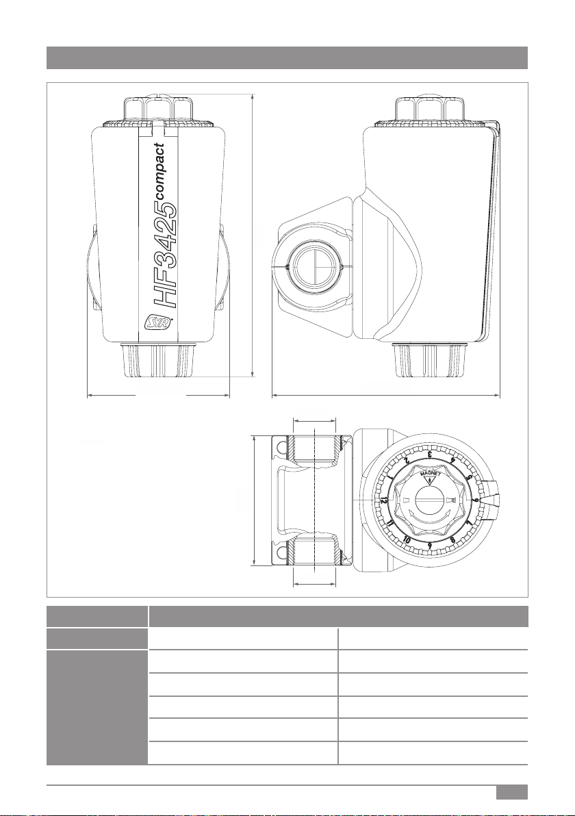
2. Übersicht2. Übersicht
Der Heizungsfilter HF 3425 compact dient zum Schutz und
zur Aufrechterhaltung der Langlebigkeit von Wärmeerzeu-
gern, Heizungspumpen, Thermostatventilen und weiteren
Armaturen in der Heizungsinstallation.
Dies gewährleistet die Kombination aus rückspülbarem
Heizungsfilter und Magnetabscheidung:
Durch den Rückspülvorgang wird der Schlamm in der
Heizungsinstallation gefiltert und ausgespült.
Die magnetischen Sedimente werden am Magnetstab
gesammelt und während der Rückspülung abgestreift und
ausgespült.
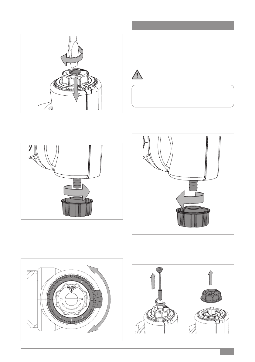
• Vor dem Einbau spülen Sie die Rohrleitungen.
• Bevorzugter Einbau ist im Rücklauf, aber auch im
Vorlauf der Heizungsanlage möglich.
• Die Rohrleitung muss das Gewicht des Heizungsfil-
ters sicher aufnehmen.
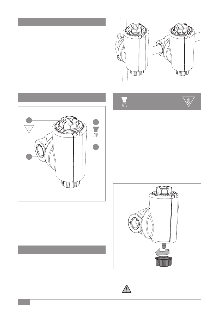
• Der Filter ist zum Flansch 360°drehbar.
• Richten Sie die Hauptachse senkrecht aus
[Bild 2 / Bild 3].
3. Einbau3. Einbau
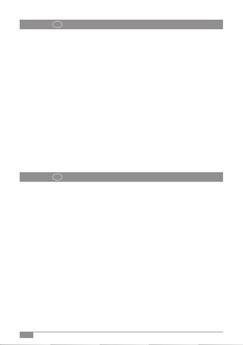
[A] Stopfen mit Magnetstab
[B] Rückspülung
[C] Drehbarer Heizungsflansch
[D] Bügel und Lünette mit Monatsmarkierung
Je nach Verschmutzungsgrad ist festzulegen, in welchen
Zyklen der Heizungsfilter rückgespült werden sollte,
um Verschmutzungen und Verschlammungen aus der
Heizungsanlage zu entfernen.
Im Allgemeinen kann der Rückspülungvorgang zusammen
mit der jährlichen Heizungswartung erfolgen.
Das nächste Rückspül- und Wartungsdatum können Sie
vormerken, indem Sie es auf der Lünette markieren. (Die
Beschreibung hierzu finden Sie auf Seite 5, Bild 12).
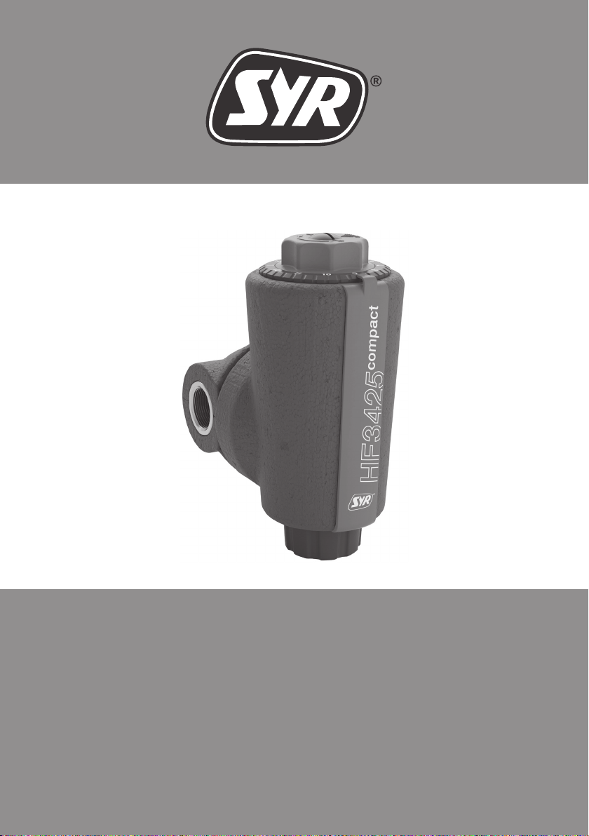
Beim Starten der Rückspülung droht
Verbrühungsgefahr durch heißes Wasser!
• Schrauben Sie zunächst die Kappe incl. Dichtung ab.
• Schieben Sie einen Schlauch über die Tülle und
sichern Sie diesen mittels Schlauchschelle.
Bild 2 Bild 3
Bild 4
Bild 1
4. Rückspülung,4. Rückspülung,
WartungWartung
AB
D
C

4
Die Austrittsmenge muss von der Ablaufleitung
bzw. vom Auffanggefäß aufgenommen werden
können!
DerStopfendarfindieserPhaselediglichGELÖST,
auf keinen Fall komplett ausgeschraubt werden! Der Magnetabscheider darf nur während der
Rückspülung gesäubert werden!
• Führen Sie das Schlauchende zum Abfluss.
• Alternativ können Sie ein Auffanggefäß benutzen.
• Drehen Sie den Stopfen komplett mit der Magnet-
Spindel heraus. Die metallischen Sedimente werden
während des laufendenRückspülvorganges abge-
streift und ausgespült.
• Lösen Sie den Stopfen mittels Schlitzschraubendre-
her so weit, dass eine freie Drehbarkeit des Griffes
gewährleistet ist..
Hinweis: Während des Rückspülvorgangs muss
der Druck der Heizungsanlage konstant gehalten
werden. Wir empfehlen die FüllCombi BA 6628 nach
DIN EN 1717.
• Drehen Sie den Griff gemäß aufgeprägter Markierung
in Pfeilrichtung bis zum Anschlag (ca. vier komplette
Umdrehungen).
• Der Rückspülvorgang ist nun gestartet
Bild 7
Bild 5
Bild 6
Bild 8
• Drehen Sie den Griff gemäß aufgeprägter Markierung
bis zum Anschlag (ca. vier komplette Umdrehungen).
• Der Rückspülvorgang ist abgeschlossen.
Bild 9

5
• Drehen Sie den Stopfen komplett mit der Magnet-
Spindel mittels Schlitzschraubendreher fest.
• Vor der Demontage kontrollieren Sie, dass sich der
Heiungsfilter in Betriebsstellung befindet.
• Schrauben Sie die Kappe incl. Dichtung ab.
• Drehen Sie den Stopfen incl. Spindel mit einem
Schlitz-Schraubendreher heraus [Bild 14].
• Nehmen Sie den Griff ab [Bild 15].
Nicht beseitigte Verschmutzungen können die Funktion des
Filters (z. B. den Durchfluss) beeinträchtigen.
In diesem Fall kann der Austausch des Filterelementes
erforderlich werden.
(Ersatzteil-Bestellnummer 3425.00.900)
• Lösen Sie die Schlauchschelle und entfernen Sie den
Schlauch.
• Drehen Sie die Kappe incl. Dichtung fest.
Bild 13
Bild 10
Bild 11
Bild 14 Bild 15
5. Demontage5. Demontage
Bevor Sie mit der Demontage beginnen, machen
Sie den Filter drucklos!
Hinweis: Wir empfehlen Ihnen, vor und hinter den
Heizungsfilter HF 3425 compact Wartungsabsper-
rungen zu setzen.
Bild 12
Sie haben nun die Möglichkeit, das nächste Rückspül- und
Wartungsdatum zu markieren:
• Wählen Sie die Monatskerbe auf der Lünette und
richten Sie die Markierung zum Bügel aus. Die Pfeil-
kontur rastet in die ausgewählte Kerbe ein.

6
• Lösen Sie die Rastnase des Bügels [A] vorsichtig,
um diesen zusammen mit der Lünette [B] nach oben
abzunehmen.
• Ziehen Sie die Filterisolierschalen zur Seite ab.
• Benutzen Sie den Montageschlüssel, um die Schraub-
kappe abzuschrauben [Bilder 18 / 19].
• Schrauben Sie die neue Schraubkappe + Filtereinheit
(Ersatzteil-Bestellnummer 3524.00.900) mit Hilfe des
Montageschlüssels fest.
• Bauen Sie den Filter in umgekehrter Reihenfolge
[Bilder 17 bis 13] zusammen.
Bild 16
Bild 17
Bild 19
Bild 18
6. Technische Daten6. Technische Daten
Anschlussgröße: DN 25
Max. Betriebsdruck: 10 bar
Betriebstemperatur: 10 °C - 110 °C
Medium: Heizungswasser
Min. Druck Rückspülung:
1,5 bar
Einbaulage: Hauptachse senkrecht
Maschenweite: 100 µm
Durchflussleistung: 2,56 m³/h bei Δp 0,1 bar
3,20 m³/h bei Δp 0,15 bar
3,60 m³/h bei Δp 0,18 bar
Kvs-Wert: 8,0
Die Installation und Wartung darf nur durch einen
autorisierten Fachbetrieb vorgenommen werden.
Wartungshinweise beachten! Kunststoffteile nicht
mit lösungsmittelhaltigen Pflegemitteln reinigen.
Filter vor Frost schützen.
Nach harten Stößen oder Schlägen muss das be-
troffene Kunststoffteil ausgewechselt werden (auch
ohne erkennbare Schäden). Starke Druckschläge,
z.B. durch nachfolgende Magnetventile, sind zu
vermeiden (Berstgefahr).
Die Verpackung dient als Transportschutz. Bei
erheblichen Beschädigungen der Verpackung ist die
Armatur nicht einzubauen!
B
A

7
7. Abmessungen7. Abmessungen
B2B1
A
A
H
B3
Typ Heizungsfilter HF 3425 compact
Nennweite DN 25
Baumaße
A Rp 1“
H 218 mm
B1 110 mm
B2 176 mm
B3 100 mm

8
Position Ersatzteil-Benennung Bestellnummer
1Schraubkappe mit Filtereinheit incl. Montageschlüssel 3425.00.900
2Lünette 3425.00.901
3Bügel 3425.00.902
4Kappe mit Dichtung 3425.00.903
8. Ersatzteile
2
3
4
1

9
9. Zubehör
AnschlussCenter 3200
3200.15.010
FüllCombi BA
6628.20.008

10
1. Range of use1. Range of use
2. Overview2. Overview
The HF 3425 compact heating filter is used to protect and
maintain the longevity of heat generators, heating pumps,
thermostatic valves and other fittings in the heating
installation.
This is ensured by the combination of backwashable heating
filter and magnetic separation:
The backwashing process filters and flushes out the sludge
in the heating installation.
The magnetic sediments are collected on the magnetic rod
and stripped off and flushed out during the backwashing
process.
• Before installation flush the pipes.
• Preferred installation is in the return, but also
possible in the flow of the heating system.
• The filter can be rotated 360° to the flange.
• Align the main axis vertically
[images 2 / 3]
3. Installation3. Installation
[A] Plug with magnetic rod
[B] Backwashing
[C] Rotatable heating flange
[D] Bracket and bezel with month marking
Depending on the degree of contamination, it must be
determined in which cycles the heating filter should be
backwashed in order to remove contamination and sludge
from the heating system.
Generally, the backwashing process can be done together
with the annual heating system maintenance.
You can note the next backwashing and maintenance date
by marking it on the bezel.
(The description for this can be found on page 12,
image 12).
When starting the backwashing process,
there is a risk of scalding from hot water!
• First unscrew the cap incl. seal.
• Slide a hose over the grommet and back it up with a
hose clamp.
image 2 image 3
image 4
image 1
4. Backwashing,4. Backwashing,
maintenancemaintenance
AB
D
C

11
Thedischargequantitymustbeabletobeabsorbed
by the discharge pipe or the collecting vessel!
The plug may only be loosened during this phase,
never completely unscrewed! The magnetic separator may only be cleaned
during backwashing!
• Lead the end of the hose to the drain.
• Alternatively, you can use a collecting vessel.
• Turn the plug completely out with the magnetic rod.
The metallic sediments are wiped off and rinsed out
during the ongoing backwashing process.
• Loosen the plug by means of a slotted screwdriver so
far that free rotation of the handle is ensured.
Note: During the backwashing process, the pressure
of the heating system must be kept constant. We
recommend the FillingCombi BA 6628 according to
DIN EN 1717.
• Turn the handle according to the imprinted marking
in the direction of the arrow as far as possible
(approximate four complete turns).
• The backwashing process has now started
image 7
image 5
image 6
image 8
• Turn the handle according to the imprinted marking
as far as possible (approximate four complete turns).
• The backwashing process is completed.
image 9

12
• Tighten the plug completely with the magnet spindle
using a screwdriver.
• Before disassembly, check that the heating filter is in
the operating position.
• Unscrew the cap incl. seal.
• Unscrew the plug incl. spindle with a slotted
screwdriver [image 14].
• Remove the cap.
Contamination that has not been removed can impair the
function of the filter (e.g. the flow rate).
Inthis case,it maybenecessary,toreplacethefilterelement.
(Spare part order number 3425.00.900)
• Loosen the hose clamp and remove the hose.
• Screw the cap incl. seal tight.
image 13
image 10
image 11
image 14 image 15
5. Disassembly5. Disassembly
Before you start with disassembly, depressurise
the filter!
Note:Werecommendplacingmaintenanceshut-offsin
frontofandbehindtheHF3425compactheatingfilter.
image 12
You now have the option of marking the next backwashing
and maintenance date:
• Select the month notch on the bezel and align the
mark with the bail. The arrow contour snaps into the
selected notch.

13
• Carefully loosen the latching lug of the bracket [A] to
remove it together with the bezel [B] upwards.
• Pull the insulating shells off to the side.
• Use the assembly spanner to unscrew the cap
[images 18 / 19].
• Screw on the new cap + filter unit (spare part
number 3524.00.900) using the assembly spanner.
• Assemble the filter in reverse direction
[images 17 to 13].
image 16
image 17
image 19
image 18
6. Technical data6. Technical data
Nominalsize: DN 25
Max. operating pressure: 10 bar
Operating temperature: 10 °C - 110 °C
Medium: heating water
Min. pressure backwashing:
1,5 bar
Installation position: main axis vertical
Mesh width: 100 µm
Flow rate: 2,56 m³/h at Δp 0,1 bar
3,20 m³/h at Δp 0,15 bar
3,60 m³/h at Δp 0,18 bar
Kvs value: 8,0
Installation and maintenance may only be carried
out by an authorised specialist company. Observe
the maintenance instructions! Do not clean plastic
parts with cleaning agents containing solvents.
Protect filter from frost.
After hard impacts or blows, the affected plastic
part must be replaced (even without visible
damage). Avoid strong pressure shocks, e.g. from
subsequent solenoid valves (danger of bursting).
The packaging serves as transport protection. In
case of considerable damage to the packaging, the
fitting must not be installed!
B
A

14
7. Dimensions7. Dimensions
B2B1
A
A
H
B3
Type Heating filter HF 3425 compact
Nominal size DN 25
Dimensions
A Rp 1“
H 218 mm
B1 110 mm
B2 176 mm
B3 100 mm

15
Position Spare part designation order number
1Screw cap with filter unit incl. mounting key 3425.00.900
2Bezel 3425.00.901
3Bracket 3425.00.902
4Cap with seal 3425.00.903
8. Spare parts
2
3
4
1

16 printed in Germany - 9.3425.00 2138 - Änderungen vorbehalten - subject to changes
Hans Sasserath GmbH & Co. KGHans Sasserath GmbH & Co. KG • Tel.: +49 2161 6105-0 • Fax: +49 2161 6105-20
Mühlenstraße 62 • D-41352 Korschenbroich • info@SYR.de • www.SYR.de
9. Zubehör
Connecting Center 3200
3200.15.010
9. Accessories
BA-Filling-Combi
6628.20.008
This manual suits for next models
1
Table of contents
Languages:
Other SYR Water Filtration System manuals
Popular Water Filtration System manuals by other brands

Metasys
Metasys COMPACT Dynamic Equipment Logbook Assembly, operation and maintenance

Miditech
Miditech MIDI THRU 4/ FILTER owner's manual

Orival
Orival OR-02-PE Operation and maintenance manual

Pentair
Pentair Everpure 2JT Product bulletin

Drinking Fountain Doctor
Drinking Fountain Doctor EFHA8 1G Installation use and care manual

RMS
RMS LTW-4Z1 Operation & installation instructions