211480 | B003
Contents
1 Declaration of Conformity .................................5
2 Disposal and recycling ......................................6
3 Warnings.......................................................6
4 About this document........................................6
5 Product information .........................................6
5.1 General................................................6
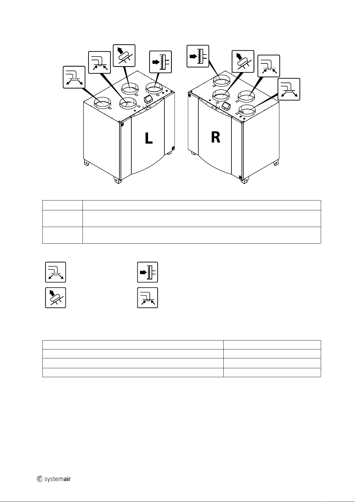
5.2 Left and Right models .............................7
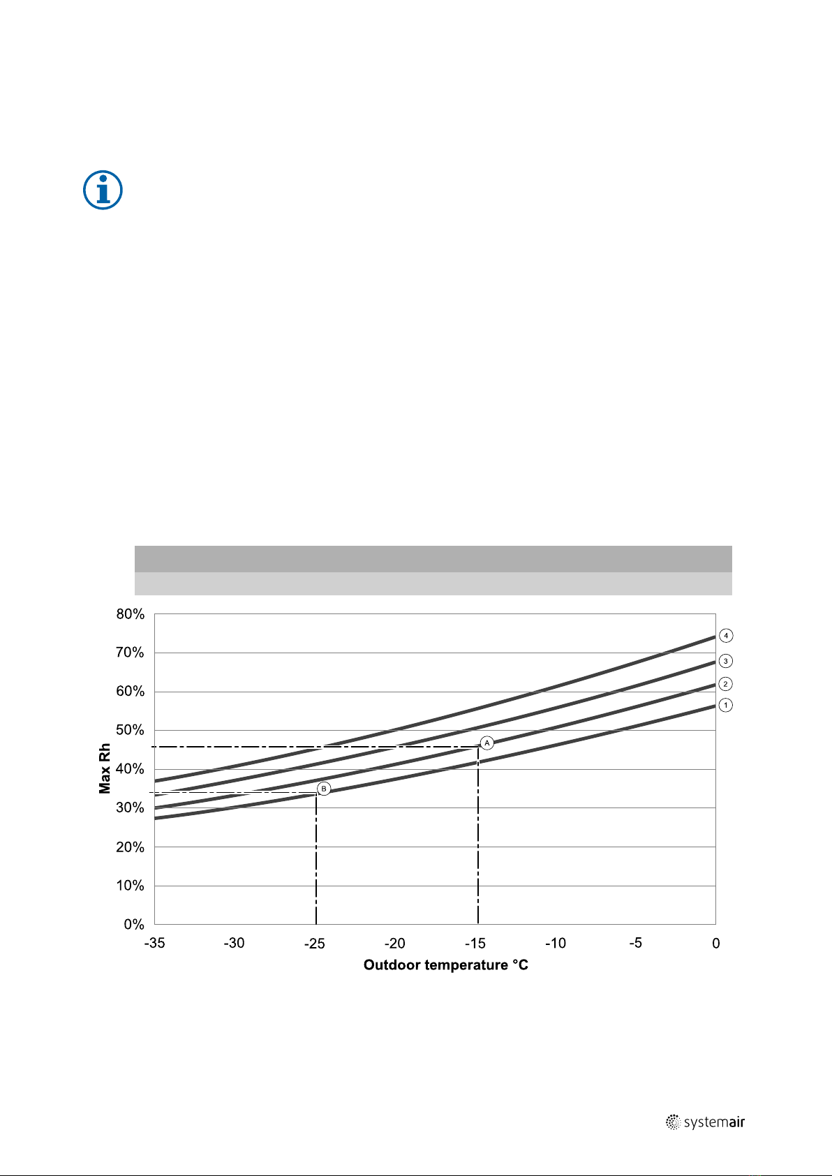
5.3 Installation recommendation regarding
condensation ........................................7
5.3.1 Condensation inside of the
unit.........................................7
5.3.2 Condensation outside of the
unit.........................................7
5.4 Transport and storage .............................8
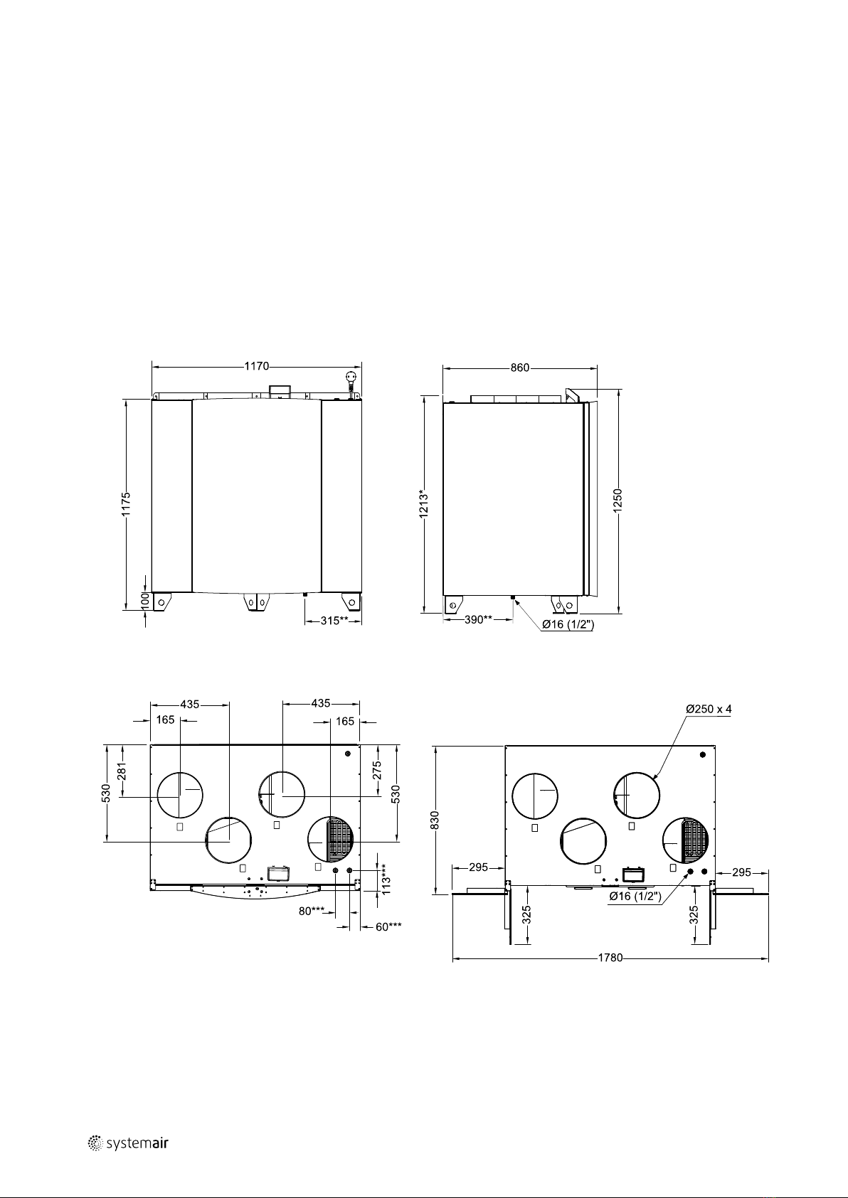
5.5 Technical data .......................................8
5.5.1 Dimensions and Weight, R
model......................................8
5.5.2 Dimensions and Weight, L
model......................................9
5.5.3 Duct connections...................... 10
5.5.4 Power consumption and fuse
size.......................................10
5.5.5 Required space ........................ 10
5.6 System curves..................................... 11
5.6.1 Supply air, M5/ePM10 60%
type filter ............................... 11
5.6.2 Extract air, M5/ePM10 60%
type filter ............................... 12
6 Installation................................................... 12
6.1 Unpacking .......................................... 12
6.2 Where/how to install ............................ 12
6.3 Condensation drainage.......................... 12
6.4 Installing the unit.................................. 13
6.4.1 Installation procedure................ 13
7 Electrical connections..................................... 14
7.1 Main board layout ................................ 14
7.2 External connections (Connection
board) ...............................................16
8 Before starting the system .............................. 16
9 Configuration ............................................... 16
9.1 General.............................................. 16
9.2 Startup wizard ..................................... 17
9.3 Common symbols................................. 17
9.4 Menu overview ................................... 17
9.5 Home screen....................................... 18
9.5.1 User modes ............................ 18
9.5.2 Temperature settings ................ 20
9.5.3 Airflow settings ....................... 20
9.5.4 Indoor Air Quality ..................... 21
9.5.5 Status line .............................. 21
9.6 Description of User function icons ............ 21
9.7 Main menu ......................................... 22
9.7.1 Unit Information ................ 23
9.7.2 Alarms .................................23
9.7.3 Week Schedule......................27
9.7.4 Filter .................................28
9.7.5 System Preferences.............28
9.7.6 Service ...............................28
9.7.7 Help.....................................36
10 Service .......................................................36
10.1 Warnings............................................ 36
10.2 Internal Components............................. 37
10.2.1 Description of
Components ........................... 37
10.3 Troubleshooting................................... 38
11 Accessories.................................................. 40
11.1 Internet Access Module (IAM) ................. 40
11.1.1 Setting up remote control of
the unit .................................. 41
11.2 Indoor air quality sensors ....................... 42
11.3 Temperature control ............................. 44
11.3.1 Internal electrical
reheater................................. 44
11.3.2 Electrical duct pre-
heater ...................................45
11.3.3 Internal water heater ................ 46
11.3.4 Duct water heater .................... 48
11.3.5 Duct water cooler..................... 49
11.3.6 Change-over coil for heating/
cooling function ....................... 50
11.4 Airflow control..................................... 52