System air S-BM2 User manual

S-BM2
Smoke Control Damper - MA Multi
User Manual
Fire Safety Products

2/48 | User Manual S-BM2 | 202010
Table of Contents
Good to know
Current information on all products is
available at www.design.systemair.com
Introduction . . . . . . . . . . . . . . . . . . . . . . . . . . 3
Warnings . . . . . . . . . . . . . . . . . . . . . . . . . . . . 4
Operating Conditions . . . . . . . . . . . . . . . . . . . . . 4
Installation . . . . . . . . . . . . . . . . . . . . . . . . . . . 5
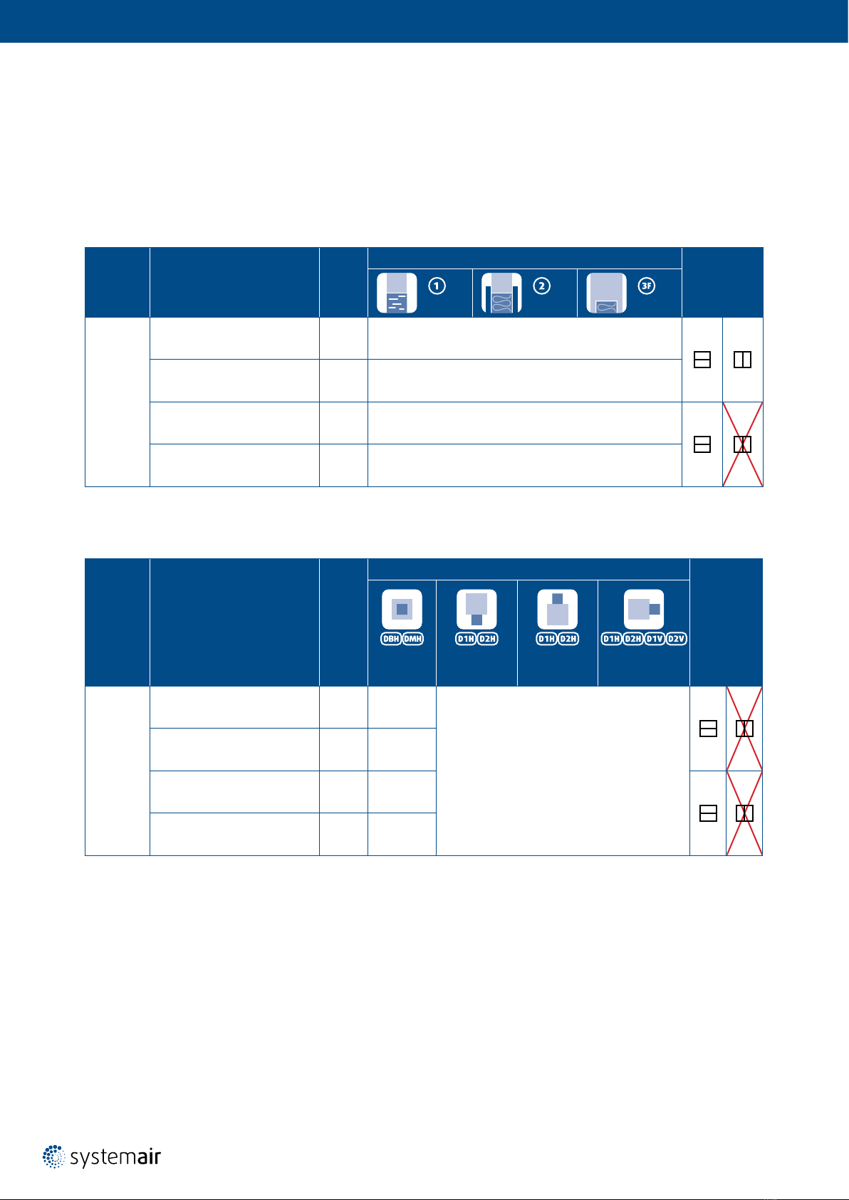
Installation Methods . . . . . . . . . . . . . . . . . . . . 6
Opening Preparation for S-BM2 Installation. . . . . . . . 8
Installation Distances . . . . . . . . . . . . . . . . . . . 10
Manipulation of S-BM2 . . . . . . . . . . . . . . . . . . 11
Wet Installation . . . . . . . . . . . . . . . . . . . . 14
Dry Installation . . . . . . . . . . . . . . . . . . . . . 18
Fit Installation . . . . . . . . . . . . . . . . . . . . . 22
Installation in the Duct Made of Promatect Boards . 26
Installation in the Duct Made of Sheet Metal. . . . . 30
Installation on the Horizontal Duct . . . . . . . . 34
Installation on the Vertical Duct . . . . . . . . . 38
Electrical Connections . . . . . . . . . . . . . . . . . . . . . 42
Operation Manual . . . . . . . . . . . . . . . . . . . . . . . 44
Smoke Control Damper Functionality Check . . . . . . . . . 44
Smoke Control Damper Inspection . . . . . . . . . . . . . . 44
Warranty Conditions . . . . . . . . . . . . . . . . . . . . . . 45
Operating Journal . . . . . . . . . . . . . . . . . . . . . . . 46
Warranty Service . . . . . . . . . . . . . . . . . . . . . . . 48

2/48 | User Manual S-BM2 | 202010 202010 | User Manual S-BM2 | 3/48
Introduction
This is the original installation, inspection and operating instructions document for the S-BM2 smoke control damper.
EVERY S-BM2 SMOKE CONTROL DAMPER NEEDS TO BE INSTALLED IN ACCORDANCE WITH THIS DOCUMENT!
S-BM2
Multiblade smoke control damper with or without mesh for installations in the wall, on the vertical or horizontal duct.
Dimension range (mm): W× H= 200 × 425 up to 1000 × 1225
1396-CPR-0157
Wet Installation
Maximum performance up to EI120S
Using Plaster/Mortar/Concrete Filling
Dry Installation
Maximum performance up to EI120S
Using Mineral Wool and Cover Boards
NOTE: *Fire resistivity depends on the type of installation.
Fit Installation
Maximum performance up to EI120S
Wall Installation Using Mineral Wool
Installation in the Duct Made of Promatect Boards
Installation in the Duct Made of Sheet Metal
Installation on the Horizontal Duct - Flush with Edges
Installation on the Horizontal Duct - Surface
Installation on the Vertical Duct - Flush with Edges
Installation on the Vertical Duct - Surface

4/48 | User Manual S-BM2 | 202010
Warnings
Some damper parts may have sharp edges – therefore, to protect yourself from harm, please use gloves during
damper installation and manipulation. In order to prevent electric shock, re or any other damage which could result
from incorrect damper usage and operation, it is important to:
1. ensure that installation is performed by a trained person.
2. follow the written and depicted instructions provided within this User Manual closely.
3. perform damper inspection in accordance with this User Manual.
4. check the damper’s functionality as per the “Smoke Control Damper Functionality Check” chapter before you
install the smoke control damper. This procedure prevents the installation of a damper that has been damaged
during transportation or handling.
IMPORTANT: Do not install non-functioning dampers!
Operating Conditions
S-BM2 smoke control damper is intended:
• for installation in places which are protected against weather disruptions.
• for ducts distributing air without any mechanical or chemical contamination.
• for maximum air ow velocity 12 m/s.
• for storage temperature minimum -20°C and maximum 50°C.
Accessory:
• K1-S-BM2: Kit for Duct Installation

4/48 | User Manual S-BM2 | 202010 202010 | User Manual S-BM2 | 5/48
Installation
• The duct connected to the smoke control damper must be supported or hung in such a way that the damper does
not carry its weight. The damper must not support any part of the surrounding construction or wall which could
cause damage and consequent damper failure.
• Easy access to mechanism and internal parts during inspection must be considered during damper placement.
• According to the standard EN 1366-2, the distance between the smoke control damper bodies must be at least 200 mm.
• The distance between smoke control damper and the adjacent wall/ceiling and the smoke control damper must be
at least 75 mm.
• When the S-BM2 smoke control damper is installed into a smoke and re partition structure, it must be placed
so that the damper blades in its closed position are located inside this structure.
• The gap in the installation opening between the smoke control damper and the wall/ceiling can be increased
by up to 50% of the gap area or decreased to the smallest amount possible that still provides sufcient space
for the installation of the seal.
• When using non-original grilles, the gap between the damper blade in open position and the self-standing grill,
mesh, louvre must be at least 200 mm according to EN 1366-10.
• The smoke control damper must be earthed after being installed into or onto the duct.
• Lists of all permitted installation methods are provided on following pages.

6/48 | User Manual S-BM2 | 202010
Installation Methods
S-BM2 Smoke control dampers are CE certied following the Construction Products Regulation according to EN 12101-8:2011.
Tested according to EN 1366-10:2011 + A1:2017, EN 1366-2:2015 and classied according to EN 13501-4:2016.
The smoke control damper together with its installation form an inseparable part of the re resistivity rating.
Tab. 1: Fire resistivity of S-BM2 - wall mounted
Dimension
Range
(mm)
Classication
Supporting
Construction
Construction Type/Minimal Thickness (mm) Allowed
Blade Axis
Orientation
Wet Dry Fit
200 × 425
up to
1000 × 1225
EI90 (vew i ↔ o) S1000 Cmod MAmulti Wall Rigid/125
Flexible/125
EI90 (how i ↔ o) S1000 Cmod MAmulti Floor/
ceiling -
EI120 (vew i ↔ o) S1000 Cmod MAmulti Wall Rigid/125
Flexible/125
EI120 (how i ↔ o) S1000 Cmod MAmulti Floor/
ceiling -
Dimension
Range
(mm)
Classication
Duct Orientation
Applicable Duct Tested per Standard
Allowed
Blade Axis
Orientation
In the Duct On the Duct/
Bottom Mounted
On the Duct/
Top Mounted
On the Duct/
Side Mounted
200 × 425
up to
1000 × 1225
EI90 (ved i ↔ o) S1000 Cmod MAmulti Horizontal
duct
EN 1366-9,
EN 1366-8
EN 1366-9,
EN 1366-8
EI90 (hod i ↔ o) S1000 Cmod MAmulti Vertical
duct -
EI120 (ved i ↔ o) S1000 Cmod MAmulti Horizontal
duct
EN 1366-9,
EN 1366-8
EI120 (hod i ↔ o) S1000 Cmod MAmulti Vertical
duct -
Tab. 2: Fire resistivity of S-BM2 - duct mounted

6/48 | User Manual S-BM2 | 202010 202010 | User Manual S-BM2 | 7/48
Legend
Wet Installation
Dry Installation
Fit Installation
Damper placed on duct surface, bottom side of the duct
Damper placed on duct surface, top side of the duct
Damper placed on duct surface, left and right side of the duct
Damper placed within the duct canal, outside of supporting construction
Installation in the duct made of promatect boards
Installation in the duct made of sheet metal
Installation on the horizontal duct - ush with edges
Installation on the horizontal duct - surface
Installation on the vertical duct - ush with edges
Installation on the vertical duct - surface
Horizontal blade axis orientation of the damper
Vertical blade axis orientation of the damper

8/48 | User Manual S-BM2 | 202010
Opening Preparation for S-BM2 Installation
The S-BM2 smoke control damper can be installed in a supporting construction between zones classied
as “multi-multi”, “multi-single” and “single-multi”.
Opening Preparation for a Rigid Wall
Fig. 1: Rigid wall/ceiling with a rectangular opening
NOTE: Dimensions W1and H1 are dened in every installation
Tab. 3: Thickness of tested wall
Fire Resistivity
Minimum s(mm)
Wall
Concrete/Masonry/Cellular Concrete
90 125 ± 10
120 150 ± 10
Legend
1 Concrete/Masonry/Cellular Concrete
s
1
W
1
H1

8/48 | User Manual S-BM2 | 202010 202010 | User Manual S-BM2 | 9/48
Opening Preparation for a Flexible Wall
Fig. 2: Flexible (plasterboard) wall with a rectangular opening and vertical cross-section (right)
Tab. 4: Thickness of tested wall
Fire Resistivity
Minimum sMinimum sCW Allowed Metal
Stud Group
Thickness
of Plasterboards
Insulation
Thickness Cubic Density
(mm) (mm) (kg/m3)
90 125 75 B, C 12,5 40 ... 50 80 ... 115
120 150 100 C 60 ... 70 85 ... 115
Legend
1On each side - 2 layers of plasterboard reproof plate type F, EN 520 (thickness see Tab. 4)
2Vertical CW-proles (proles with sCW based on re resistivity, see Tab. 4)
3Horizontal UW-proles (prole with sCW based on re resistivity, see Tab. 4)
4 Mineral wool; thickness/cubic density see Tab. 4)
4
1
3
H1× W1
s
sCW
s
H1
W
1
ma
x
.
6
25
3
4
2
1
A
A
B
B

10/48 | User Manual S-BM2 | 202010
Installation Distances
According to the EN 1366-2 standard, the minimum distance from the wall or ceiling to the damper body is 75 mm.
For multiple crossings through a re resistive wall, the minimum distance between two damper bodies is 200 mm.
This applies for distances between the damper body and a nearby foreign object crossing the re resistive wall.
Damper clearances vary from the type of mechanism and their rotation (see Fig. 3).
Fig. 3: Installation distances between damper bodies
≥200
≥75 s
≥200≥75

10/48 | User Manual S-BM2 | 202010 202010 | User Manual S-BM2 | 11/48
Manipulation of S-BM2
The S-BM2 is made of boards and can thus be considered fragile. Handling and manipulation must be done with care.
Smaller dimensions can be manipulated and placed in the installation opening by two persons. Bigger dimensions are
supplied with wooden blocks, those serve as support for suitable lifting equipment (forklift, crane).
Please follow both textual and graphic instructions (Fig. 4 up to Fig. 10):
1. Unpack the damper and place it in vertical position.
2. Remove grille and place the holder between the upper-most blade and the frame.
3. Carefully lift the smoke control damper with the forklift, crane.
4. Prepare the opening, damper hanger, connection surfaces and/or lling as per the desired installation type.
5. Place the smoke control damper in the opening (wall installation) or on the opening (duct installation).
6. Once the smoke control damper has been placed x the damper to ductwork:
a) For wall installation - insert the lling as per desired installation.
b) For duct installation – x the hangers so that the weight of the damper is supported.
7. Carefully remove the fork.
8. Remove the wooden support.
9. If the ductwork ends with the damper – install a grille or grilles.
Fig. 4: Unpack the damper and place it in vertical position
Fig. 5: Remove grille and place the holder between the upper-most blade and the frame.
NOTE: Y1 = Cutting plane
Y₁
180
50
25
1.
2.

12/48 | User Manual S-BM2 | 202010
Y₂
Fig. 6: Carefully lift the smoke control damper with the forklift, crane.
NOTE: Y2= Cutting plane
Fig. 7: Prepare the opening, damper hanger, connection surfaces and/or lling as per the desired installation type
Place the smoke control damper in the opening (wall installation) or on the opening (duct installation).
3.
4. 5.

12/48 | User Manual S-BM2 | 202010 202010 | User Manual S-BM2 | 13/48
Y₃
Fig. 8: Once the smoke control damper has been placed x the damper to ductwork:
a) For wall installation - insert the lling as per desired installation.
b) For duct installation – x the hangers so that the weight of the damper is supported.
NOTE: Y3= Cutting plane
b)
a)
Fig. 9: Carefully remove the fork. Remove the wooden support.
6.
7. 8. 9.
Fig. 10: If the ductwork ends with the damper – install a grille or grilles.
NOTE: Y4= Cutting plane
Y₄

Wet
14/48 | User Manual S-BM2 | 202010
Wet Installation
Wall Installation Using Plaster/Mortar/Concrete Filling
1. The supporting construction opening must be prepared in a way depicted in the “Opening Preparation for
S-BM2 Installation” section (as per Fig. 1 and Fig. 2). Opening surfaces must be even and cleaned off.
The exible wall opening must be reinforced as per the standards for plasterboard walls.
The opening dimensions are driven by the nominal dimensions of the damper with added clearance.
The opening will be with the dimensions of W1and H1( Fig. 11).
2. Insert the closed damper as per the “Manipulation of S-BM2” section into the middle of the opening so that
the damper blade is in the wall. For damper widths greater than 600 mm, it is recommended to use a duct support
inside the damper during installation to avoid any damage caused to the damper housing by the weight of the lling.
3. Fill in the area between the wall and the damper with gypsum plaster or mortar or concrete lling (3)
while paying attention to prevent the fouling of the damper’s functional parts, which could limit its correct
functionality. The best way is to cover the functional parts during installation.
To prevent seepage of the lling material, use of boards is recommended.
First, let the plaster or mortar or concrete lling harden and then perform the next steps.
4. After the lling hardens, remove the duct support from inside of the damper.
5. If needed, uncover and clean the damper after installation.
6. Check the functionality of the damper.
Dimension
Range
(mm)
Classication Supporting
Construction
Construction Type/Minimal Thickness (mm) Allowed
Blade Axis
Orientation
Wet
200 × 425
up to
1000 × 1225
EI90 (vew i ↔ o) S1000 Cmod MAmulti Wall Rigid/125
Flexible/125
EI90 (how i ↔ o) S1000 Cmod MAmulti Floor/ceiling -
EI120 (vew i ↔ o) S1000 Cmod MAmulti Wall Rigid/125
Flexible/125
EI120 (how i ↔ o) S1000 Cmod MAmulti Floor/ceiling -
Legend for gures of Wet installation
1 Smoke control damper S-BM2
2 Connected ductwork made of Promatect-L500 boards (min. 500 kg/m3, Promat)
3Plaster/mortar/concrete lling
4 Grille
5 Nails or pins per ductwork manufacturer instructions
6 Fire resistive coating Promat K84 (Promat)
Y Cutting plane
Horizontal blade axis orientation of the damper
Vertical blade axis orientation of the damper

Wet
14/48 | User Manual S-BM2 | 202010 202010 | User Manual S-BM2 | 15/48
Fig. 11: Wet installation of S-BM2 smoke control damper
H₁=(H+80)+40
2
13 Y
W₁=(W+270)+40

Wet
16/48 | User Manual S-BM2 | 202010
Y₁
10
2
5
50
20
H₁ × W₁
≥50 3 1
6
≥50
≥10≥10
240
≥50
≥50
12,5
125
Y₂
Y₃ Y₄
Y1Cross-section of Wet installation in exible wall (aligned on the outside)
Y2Cross-section of Wet installation in rigid wall (aligned on the outside)
Y3Cross-section of Wet installation in exible wall (aligned on the inside)
Y4Cross-section of Wet installation in rigid wall (aligned on the inside)
Y5Cross-section of Wet installation in exible wall ended with grille (aligned on the outside)
Y6Cross-section of Wet installation in rigid wall ended with grille (aligned on the outside)
Y7Cross-section of Wet installation in exible wall ended with grille (aligned on the inside)
Y8Cross-section of Wet installation in rigid wall ended with grille (aligned on the inside)
Y9Cross-section of Wet installation in exible wall ended with grille on both sides
Y10 Cross-section of Wet installation in rigid wall ended with grille on both sides
Legend

Wet
16/48 | User Manual S-BM2 | 202010 202010 | User Manual S-BM2 | 17/48
Y₅
10
2
5
50
20
H₁ × W₁
43 1
6
≥50
≥10≥10
240
≥50
12,5
125
Y₆
Y10
Y₇ Y₈
Y₉
H₁ × W₁
20
13
≥50 4
≥10≥10
240
12,5
125

Dry
18/48 | User Manual S-BM2 | 202010
Dry Installation
Wall Installation Using Mineral Wool and Cover Boards
1. The supporting construction opening must be prepared in a way depicted in the “Opening Preparation for
S-BM2 Installation” section (as per Fig. 1 and Fig. 2). Opening surfaces must be even and cleaned off.
The exible wall opening must be reinforced as per the standards for plasterboard walls.
The opening dimensions are driven by the nominal dimensions of the damper with added clearance.
The opening will be with the dimensions of W1and H1( Fig. 12).
2. Insert the damper as per the “Manipulation of S-BM2” section into the middle of the opening so that the damper
blade is in the wall. For damper widths greater than 600 mm, it is recommended to use a duct support inside
the damper during installation to avoid any damage caused to the damper housing by the weight of the lling.
3. Fill in the area between the wall and the damper with mineral wool (3) with a density of at least 100 kg/m3
thoroughly but in such a way that will not deform the duct.
4. Close the gap between the damper and the mounting opening, use gypsum boards (7) with screws (8)
which x the gypsum boards to wall.
5. All the gaps between gypsum boards and the wall and between gypsum boards and the connected ductwork
made of Promatect boards need to be lled with putty for gypsum boards (9; e.g. Rigips Super)
6. Check the functionality of the damper.
Dimension
Range
(mm)
Classication Supporting
Construction
Construction Type/Minimal Thickness (mm) Allowed
Blade Axis
Orientation
Dry
200 × 425
up to
1000 × 1225
EI90 (vew i ↔ o) S1000 Cmod MAmulti Wall Rigid/125
Flexible/125
EI90 (how i ↔ o) S1000 Cmod MAmulti Floor/ceiling -
EI120 (vew i ↔ o) S1000 Cmod MAmulti Wall Rigid/125
Flexible/125
EI120 (how i ↔ o) S1000 Cmod MAmulti Floor/ceiling -
Legend for gures of Dry installation
1 Smoke control damper S-BM2
2 Connected ductwork made of Promatect-L500 boards (min. 500 kg/m3, Promat)
3Mineral wool lling (min. 100 kg/m³)
4 Grille
5 Nails or pins per ductwork manufacturer instructions
6 Fire resistive coating Promat K84 (Promat)
7 Gypsum boards
8Screws for xing gypsum boards to: exible wall (TN 3,5×35)/rigid wall (HUS-CR 8×65)
9 Putty for gypsum boards, e.g. Rigips Super
Y Cutting plane
Horizontal blade axis orientation of the damper
Vertical blade axis orientation of the damper

Dry
18/48 | User Manual S-BM2 | 202010 202010 | User Manual S-BM2 | 19/48
Fig. 12: Dry installation of S-BM2 smoke control damper
Y
2
713
H₁=(H+80)+40
W₁=(W+270)+40

Dry
20/48 | User Manual S-BM2 | 202010
Y1Cross-section of Dry installation in exible wall (aligned on the outside)
Y2Cross-section of Dry installation in rigid wall (aligned on the outside)
Y3Cross-section of Dry installation in exible wall (aligned on the inside)
Y4Cross-section of Dry installation in rigid wall (aligned on the inside)
Y5Cross-section of Dry installation in exible wall ended with grille (aligned on the outside)
Y6Cross-section of Dry installation in rigid wall ended with grille (aligned on the outside)
Y7Cross-section of Dry installation in exible wall ended with grille (aligned on the inside)
Y8Cross-section of Dry installation in rigid wall ended with grille (aligned on the inside)
Y9Cross-section of Dry installation in exible wall ended with grille on both sides
Y10 Cross-section of Dry installation in rigid wall ended with grille on both sides
Legend
Y₁
≥50
≥10
240
≥10
H₁ × W₁
10020
13
≥50
50
10
6
8
5
2
79
12,5
125
12,5
Y₂
Y₃ Y₄
Table of contents
Other System air Industrial Equipment manuals

System air
System air SAVE-P VTR 250/B User manual

System air
System air SAVE-P VTR 150/B User manual

System air
System air PAW-200W5APAC Manual

System air
System air SAVE VTR 150/K User manual

System air
System air SAVE VTR 700 Manual

System air
System air SAVE VTC 300 User manual

System air
System air KBR 280DV User manual

System air
System air SAVE VTR 250/B User manual

System air
System air GEO User manual