FIGURE 7. OSI-RE-SS TERMINALS
T1
Terminals
T3
T4
T5
T2
OSI-RE-SS Terminals
External
Jumper
10k ohm
External
Resistor
Remote Alarm Output
Remote Trouble Output
Remote Test/Reset Input
AUX -
T2-1
T2-3
T2-2
T2-4
C2058-00
FIGURE 8. REMOTE LED CONNECTIONS
Alarm
Signal
Circuit
Trouble
Signal
Circuit
Yellow
Red
T2-1
T2-2
T2-4
C2059-00
INITIALIZATION AND COMMISSIONING
Ensure that neither you nor any other objects are in the line of sight between
the detector and the reflector and start to manually align the Imager to the
reflector (See Figure 9.)
The OSP-002 Laser Alignment Tool can be used for the rough alignment if
the system is to be installed at longer distances or in heavy lit environments.
Follow these steps to adjust the optical sphere of the detector component to
align the system (See Figure 10.):
• Make sure the lever is the 3 o’clock position.
• The 4 arrows will intuitively guide the user to optimal eyeball alignment.
Likely the alignment process will start with all arrows red.
• Gently move the eyeball until all arrows and the middle green LED blink
green for the eyeball to be optimal aligned (See Figure 11.).
• When all arrows are green, gently lock the eyeball by moving the lever
down till the eyeball is solidly locked. The lever is now in the 5 o’clock
position and you feel the resistance of the locked position.
FIGURE 9. COARSE ALIGNMENT
OSP-002 Laser
Alignment Tool
C2060-00
FIGURE 10. ARROW ARRAY
C2061-00
FIGURE 11. LOCKING AND SECURING EYE BALL
C2062-00
By locking the eyeball an internal switch is activated and the detector will
now start its initiation or commissioning process. A normal commissioning
process takes roughly 10 seconds. During the commissioning process, the
beam path must remain clear from object intrusions.In this process cycle, the
detector will measure size of the reflector in the FOV and set the sensitivity
automatically to the optimum sensitivity for the specific distance.
Before going in operational mode, the detector will show its set sensitivity.
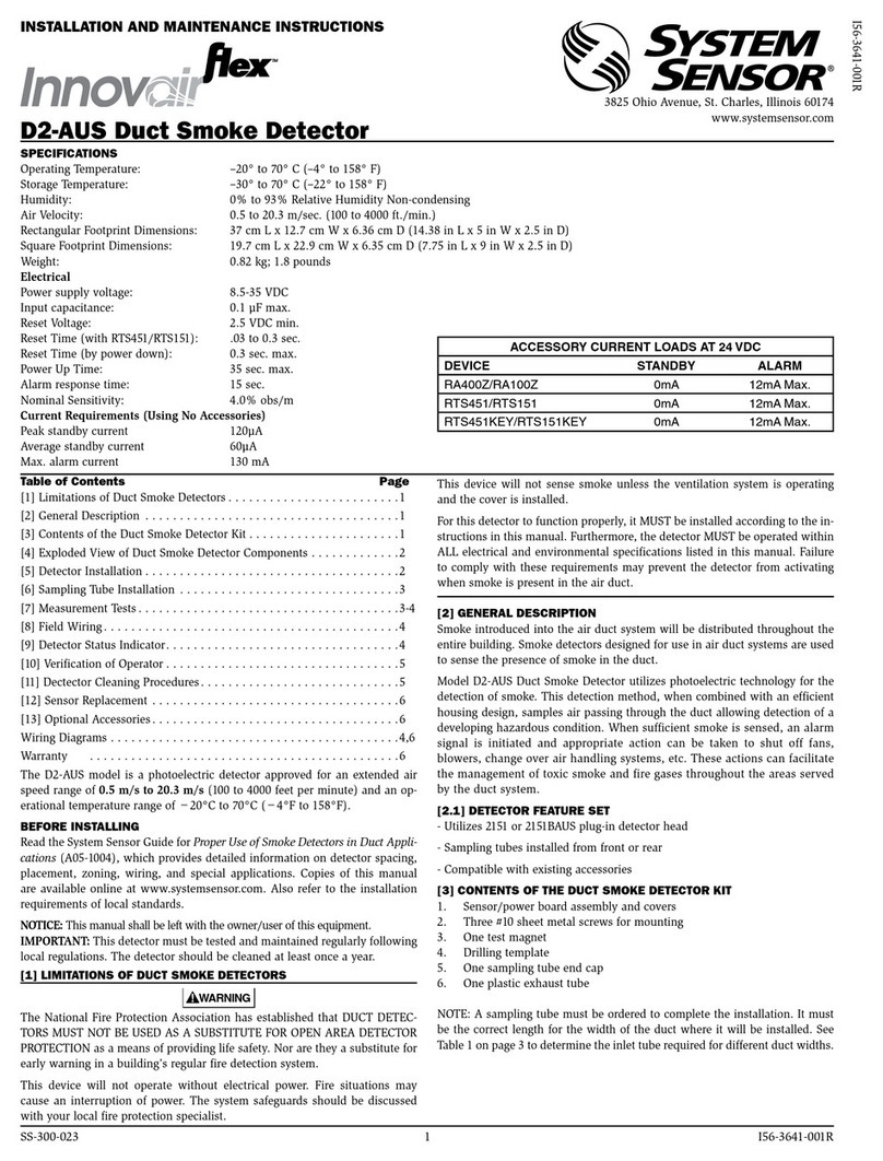
This is shown by blinking the 4 arrows to the colour yellow, reflecting the %
of selected obscuration/sensitivity. The key is; 1 blink = 25%, 2 blinks =
30%, 3 blinks = 40% and 4 blinks = 50%. After 5 seconds, the scenario will
be repeated a second time and the arrows LEDs go out and the front OK LED
blinks green. The detector is now in operation and working correctly.
The paintable rim can now be snapped over the front to secure the locking
lever and to hide the alignment LEDS and locking mechanism.
Applying the cover also secures the locking lever in position.
TESTING THE INSTALLATION
After the commissioning, the detector must be tested for correct alarming by
using the OSP-004 test filter at the reflector or using the remote test station.
When using the RTS151KEY for testing the detector, the remote fault LED will
blink the set sensitivity of the detector. The number of blinks, similar to sec-
tion 5, will represent the set sensitivity and the sequence is repeated every 3
seconds till the detector is reset.
IMAGER RESET
The fault relay is non-latching but the alarm relay is latching. The Imager
alarm can be reset by shortly dropping the supply voltage or by using a reset
station.
OPERATION AFTER A POWER FAILURE
After a power failure of any duration, when the supply is restored, the detec-
tor will check the possible new situation against its memorized data.
If the reflector is found in the same position and all parameters are within
acceptable limits, the detector will resume its operation and go out of fault
condition.
If any significant parameters have changed, it will remain in a fault condition
and a re-initialization will be required.
3 I56-6654-000
13/10/2020
