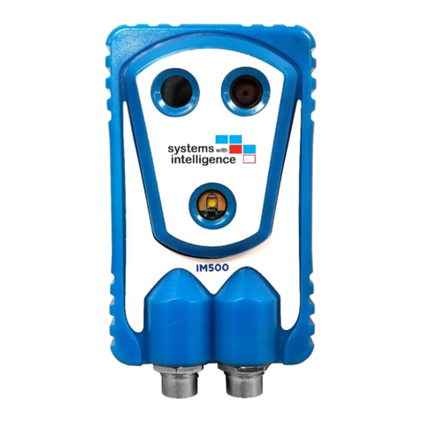
Systems With Intelligence IM500 User manual

D017-0025-301-01 IM500-SM500 Installation Guide
© 2020 Systems With Intelligence. All rights reserved.
www.SystemsWithIntelligence.com
supportSystemsWithIntelligence.com
1
Note: Please read this manual thoroughly before operating this unit and retain it for future reference.
IM500/SM500 –Industrial IoT Module
2020.08.10
Installation Guide
support@SystemsWithIntelligence.com
www.SystemsWithIntelligence.com

D017-0025-301-01 IM500-SM500 Installation Guide
© 2020 Systems With Intelligence. All rights reserved.
www.SystemsWithIntelligence.com
supportSystemsWithIntelligence.com
2
Copyright
COPYRIGHT © 2020 Systems With Intelligence Inc. ALL RIGHTS RESERVED.
Dissemination or reproduction of this document, or evaluation and communication of its contents, is not
authorized except where expressly permitted. Violations are liable for damages. All rights reserved, particularly
for the purposes of patent application or trademark registration.
This document contains proprietary information, which is protected by copyright. All rights are reserved. No part
of this document may be photocopied, reproduced or translated to another language without the prior written
consent of Systems With Intelligence Inc.
Disclaimer of Liability
We have checked the contents of this manual against the hardware and software described. However, deviations
from the description cannot be completely ruled out.
Systems With Intelligence shall not be liable for any errors or omissions contained herein or for consequential
damages in connection with the furnishing, performance, or use of this material.
The information given in this document is reviewed regularly and any necessary corrections will be included in
subsequent editions. We appreciate any suggested improvements. We reserve the right to make technical
improvements without notice.
Contacting Systems With Intelligence
6889 Rexwood Road, Unit #9, Mississauga, Ontario, L4V 1R2 Canada
Phone: +1-289-562-0126 Email: info@SystemsWithIntelligence.com
www.SystemsWithIntelligence.com
Technical Support
International +1-289-562-0126 Fax: +1-289-562-0152
Email: support @SystemsWithIntelligence.com

D017-0025-301-01 IM500-SM500 Installation Guide
© 2020 Systems With Intelligence. All rights reserved.
www.SystemsWithIntelligence.com
supportSystemsWithIntelligence.com
3
1Federal Communications Commission Radio Frequency
Interference Statement
This equipment has been tested and found to comply with the limits for a Class A digital device
pursuant to Part 15 of the FCC Rules. These limits are designed to provide reasonable protection
against harmful interference when the equipment is operated in a commercial environment. This
equipment generates, uses and can radiate radio frequency energy and, if not installed and used
in accordance with the instruction manual, may cause harmful interference to radio
communications. Operation of this equipment in a residential area is likely to cause harmful
interference in which case the user will be required to correct the interference on his own
expense.
CAUTION
This product contains no user-serviceable parts. Attempted service by unauthorized personnel
shall render all warranties null and void. Changes or modifications not expressly approved by
Systems With Intelligence Inc. could void the user’s authority to operate the equipment. Should
this device require service please contact Systems With Intelligence.
Contacting Systems With Intelligence
6889 Rexwood Road, Unit #9, Mississauga, Ontario, L4V 1R2 Canada
Phone: +1-289-562-0126 Email: info@SystemsWithIntelligence.com
www.SystemsWithIntelligence.com
Technical Support
International +1-289-562-0126 Fax: +1-289-562-0152
Email: support @SystemsWithIntelligence.com

D017-0025-301-01 IM500-SM500 Installation Guide
© 2020 Systems With Intelligence. All rights reserved.
www.SystemsWithIntelligence.com
supportSystemsWithIntelligence.com
4
2Important Safety Instructions
READ THESE INSTRUCTIONS
1. Keep these instructions.
2. Heed all warnings.
3. Follow all instructions.
4. Install in accordance with the manufacturer’s instructions.
5. Only use attachments/accessories specified by the manufacturer.
6. Refer all servicing to qualified service personnel. Servicing is required when the
apparatus has been damaged in any way, such as power supply cord or plug is
damaged, liquid has been spilled or objects have fallen into the apparatus, the
apparatus has been, does not operate normally, or has been dropped.
7. Installation should be done only by qualified personnel and conform to all local codes.
8. Use only installation methods and materials capable of supporting four times the
maximum specified load.
9. Use stainless steel hardware to fasten the mount to outdoor surfaces.
10.To prevent damage from water leakage when installing a mount outdoors on a roof or
wall, apply sealant around the bolt holes between the mount and mounting surface.
11.Only use replacement parts recommended by Systems With Intelligence.
12.Avoid aiming the camera directly to bright objects (e.g. sun) as this may damage the
image sensor and thermal sensor of the camera.
13.Do not drop the object or apply strong blows to it.
14.Keep away from locations subject to excessive vibration.

D017-0025-301-01 IM500-SM500 Installation Guide
© 2020 Systems With Intelligence. All rights reserved.
www.SystemsWithIntelligence.com
supportSystemsWithIntelligence.com
5
3Table of Contents
1Federal Communications Commission Radio Frequency Interference Statement..................... 3
2Important Safety Instructions........................................................................................................................ 4
3Table of Contents............................................................................................................................................... 5
4Introduction ......................................................................................................................................................... 6
5Components required for a typical installation ...................................................................................... 6
6Installation instructions.................................................................................................................................... 7
6.1 Step 1: Mounting of the junction box............................................................................................... 7
6.2 Step 2: Junction box electrical connections .................................................................................... 8
6.3 Step 3: Mounting the arm ...................................................................................................................10
6.4 Step 4: Connecting the power ...........................................................................................................12
6.5 Hardware interface connections .......................................................................................................12
6.6 Optional: External Antenna .................................................................................................................13

D017-0025-301-01 IM500-SM500 Installation Guide
© 2020 Systems With Intelligence. All rights reserved.
www.SystemsWithIntelligence.com
supportSystemsWithIntelligence.com
6
4Introduction
This document describes the steps to mount, connect and verify the electrical connections of the
IM500 and SM500 systems.
5Components required for a typical installation
Figure 5-1 displays and lists the components you have to purchase from SWI or supply yourself
for a typical installation. Please note that each item can be order individually.
1. Mounting Arm (p/n SM-A01); you need one arm for each camera.
2. IM500 IoT module–visual and thermal camera or SM500 IoT Modbus Sensors module.
3. Power cable (p/n PCSM-MF4P-10); you need one power cable for each camera.
4. Optional - Interface cable (p/n PTSM-M8P-01).
5. Junction box with wall-mounting brackets; part number CJBSM-05. The junction box
provides the power supply for up to five IM500/SM500 units. Optionally you could
supply 12Vdc/0.5A per camera instead of using the junction box.
Figure 5-1 Packaged items

D017-0025-301-01 IM500-SM500 Installation Guide
© 2020 Systems With Intelligence. All rights reserved.
www.SystemsWithIntelligence.com
supportSystemsWithIntelligence.com
7
6Installation instructions
6.1 Step 1: Mounting of the junction box
The junction box can be mounted on a flat surface using the included brackets. You can order
optional brackets to mount the box on a pole. The dimensions of the enclosure are presented
in Figure 6-1.
Figure 6-1 Dimensions Junction Box

D017-0025-301-01 IM500-SM500 Installation Guide
© 2020 Systems With Intelligence. All rights reserved.
www.SystemsWithIntelligence.com
supportSystemsWithIntelligence.com
8
6.2 Step 2: Junction box electrical connections
The internal components of the junction are presented in Figure 6-2.
Figure 6-2 Junction box connections

D017-0025-301-01 IM500-SM500 Installation Guide
© 2020 Systems With Intelligence. All rights reserved.
www.SystemsWithIntelligence.com
supportSystemsWithIntelligence.com
9
Connections located at the bottom of the enclosure:
a. Main power –strain relief on the left side.
b. 4-pin connectors to supply power to maximum five IM500/SM500.
c. Ground lug connection –located on the right.
The main power can be AC or DC and the specifications are listed below. There is a label
located at the bottom-right of the junction box that lists the terminal connections and input
specifications.
AC Input
•Voltage: 100Vac –240Vac 50/60Hz
•Typical current: 0.6A
•Maximum current: 3A; limited by internal breaker.
DC Input
•Voltage: 120Vdc –340Vdc
•Typical current: 0.6A
•Maximum current: 3A; limited by internal breaker.
The junction box provides power to up to five IM500/SM500 units through the 4-pin
connectors located at the bottom. The signals are shown in Table 6-1.
Table 6-1 Power Connector: Front View
Pin
Signal
1
Power (+)
2
Power (-)
3
Not connected
4
Not connected

D017-0025-301-01 IM500-SM500 Installation Guide
© 2020 Systems With Intelligence. All rights reserved.
www.SystemsWithIntelligence.com
supportSystemsWithIntelligence.com
10
6.3 Step 3: Mounting the arm
The mounting arm is shown in Figure 6-3 or Figure 6-5 and contains three parts: Mounting
base (1), Arm (2) and Camera cradle (3).
Figure 6-3 Arm, base and cradle
Instructions:
1. Disassemble the arm by turning the butterfly nut (4) and separate the mounting base (1)
and the camera cradle (3).
2. Mount the base (1) - you must mount this plate on the wall or pole. See dimensions in
Figure 6-4 or Figure 6-6.
3. Mount the camera cradle (3) on the back of the IM500/SM500 using the camera
mounting screw (5). Do not assemble the arm, proceed to the next section.
Figure 6-4 Mounting base dimensions

D017-0025-301-01 IM500-SM500 Installation Guide
© 2020 Systems With Intelligence. All rights reserved.
www.SystemsWithIntelligence.com
supportSystemsWithIntelligence.com
12
6.4 Step 4: Connecting the power
In this section you will apply power to the installation and verify the functionality. Prerequisites:
the junction box is mounted and powered is wired. Instructions:
1. Turn on the main power to the junction box if not already on.
2. Turn on the breaker in the junction box if not already on. Verify that the LED (light) of
the power supply inside the box is on.
3. Connect the IM500 power cable (4-pin connector at both ends) to the junction box. It is
possible to extend the power cable by daisy-chaining cables.
4. Connect the 4-pin connector to the IM500/SM500 and verify that the LED (light) on the
back is on (flashing or solid).
5. Assemble back the arm with the base and the IM500/SM500. For IM500 only adjust the
direction of the camera and tighten the adjusting screw (5) at the end of the installation.
6.5 Hardware interface connections
SM500 only: you must connect the RS485 serial connection to the Modbus sensors as indicated
in Table 6-3. The IM500/SM500 provides one 8-pin connector for the Digital I/O interface and
RS485 for SM500 only. The specifications of the interface are listed in Table 6-2 and the signals
are defined in Table 6-3.
Table 6-2 Digital Input/ Output specifications
Interface
Specifications
Additional Information
Two Digital
Inputs
Wetting voltage: 12Vdc (±10%)
Wetting current: 5mA
Requires an external power source to
supply the wetting voltage.
One Digital
Output
Relay output: Type-1A contact
Maximum voltage: 30Vdc
Maximum current: 500mA
This is a momentary contact.
Table 6-3 Hardware interface connections
Pin
Color
Signal
Connections
1
White
Digital Input 1 (+)
Typical connections –see Figure 6-7
2
Brown
Digital Input 1 (-)
3
Green
Digital Input 2 (+)
Typical connections –see Figure 6-7
4
Yellow
Digital Input 2 (-)
5
Gray
Relay contact 2
6
Pink
Relay contact 1
7
Blue
RS485 (+) [may be marked B]
SM500 only
8
Red
RS485 ( - ) [may be marked A]
SM500 only

D017-0025-301-01 IM500-SM500 Installation Guide
© 2020 Systems With Intelligence. All rights reserved.
www.SystemsWithIntelligence.com
supportSystemsWithIntelligence.com
13
Figure 6-7 Typical Digital Input Connections
6.6 Optional: External Antenna
The unit can be ordered with the optional external antenna using the SWI part number EA-E01.
The manufacturer part number is Taoglas Limited GSA.8821.B.301111and has a 3 meters cable
terminated with the SMA Male connector. The connector must be connected to the top of the
IM500/SM500 and the antenna must be mounted using the self-adhesive tape.

D017-0025-301-01 IM500-SM500 Installation Guide
© 2020 Systems With Intelligence. All rights reserved.
www.SystemsWithIntelligence.com
supportSystemsWithIntelligence.com
15
Systems With Intelligence Inc.
6889 Rexwood Road, Unit #9
Mississauga, Ontario, CANADA
Sales Inquiries:
sales@SystemsWithIntelligence.com
Product Support:
Other manuals for IM500
1
This manual suits for next models
1
Table of contents
Other Systems With Intelligence Control Unit manuals