SYStronics TIC-4M User manual

TIC-4M MANUAL
1
1404, 301, Bucheon Techno park, 345, Seokcheon-ro, Bucheon-si, Gyeonggi-do, Republic of Korea
Phone : +10-32-324-2777 Fax : +10-32-324-2717 Homepage : www.ss22.com
TIC-4M
USER MANUAL
Compact Temperature Controller
VER 1.0SYStronics. Co. ltd.,

TIC-4M MANUAL
2
Be sure to read and ensure that your safety precautions are used to protect your safety and prevent property
damage. We shall not accept any liability for any loss caused by the use or carelessness caused by the use
or handling of this manual.
Warning
If this product is not intended as a safety device, use a double safety device for fear of accidents, damage of
critical peripheral equipment, and equipment that is feared to cause extensive property damage.
Safety instructions
1. Be sure to check the equipment after disconnecting mains.
2. Do not disassemble and repair this product ; it is not possible to manufacture any product.
3. Do not spray water directly or clean it with benzene, jazzy, or alcohol.
Notes on the Environment
Do not install this product in the following locations and environments :
1. Places directly exposed to mechanical vibration or shock
2. Places exposed to corrosive gases or combustible gases
3. Position directly exposed directly to direct sunlight
4. Places affected by electromagnetic waves
5. Places where high temperature or humidity is high (sites with over 85 % of ambient humidity)
6. Places where dust and salt are plentiful
Precautions on installation
1. Make sure that the installation work is related to the installation or qualified personnel only.
2. Do not place any device or wiring that caused noise (NOISE) near the product.
3. Avoid near heating apparatus.
4. Disconnect all appliances (OFF) after disconnecting them from the wiring.
5. Do not work with wet hands. Risk of electric shock.
6. Install and use the method described in the User Manual as instructed in the Instructions for Use.
7. Do not turn on (power on) prior to the connection between the unit of manufacture of this unit.
8. Do not use any load exceeding the opening and closing capacity of the output contacts.
Immunity condition
1. In addition to the contents set forth herein, no warranties and responsibilities shall be made regarding this
product.
2. Whether or not this product is likely to be unforeseen defects and natural disasters due to the use of this
product, the user or the third person We shall not be held liable for any indirect damage.
Precautions

TIC-4M MANUAL
3
Product Overview
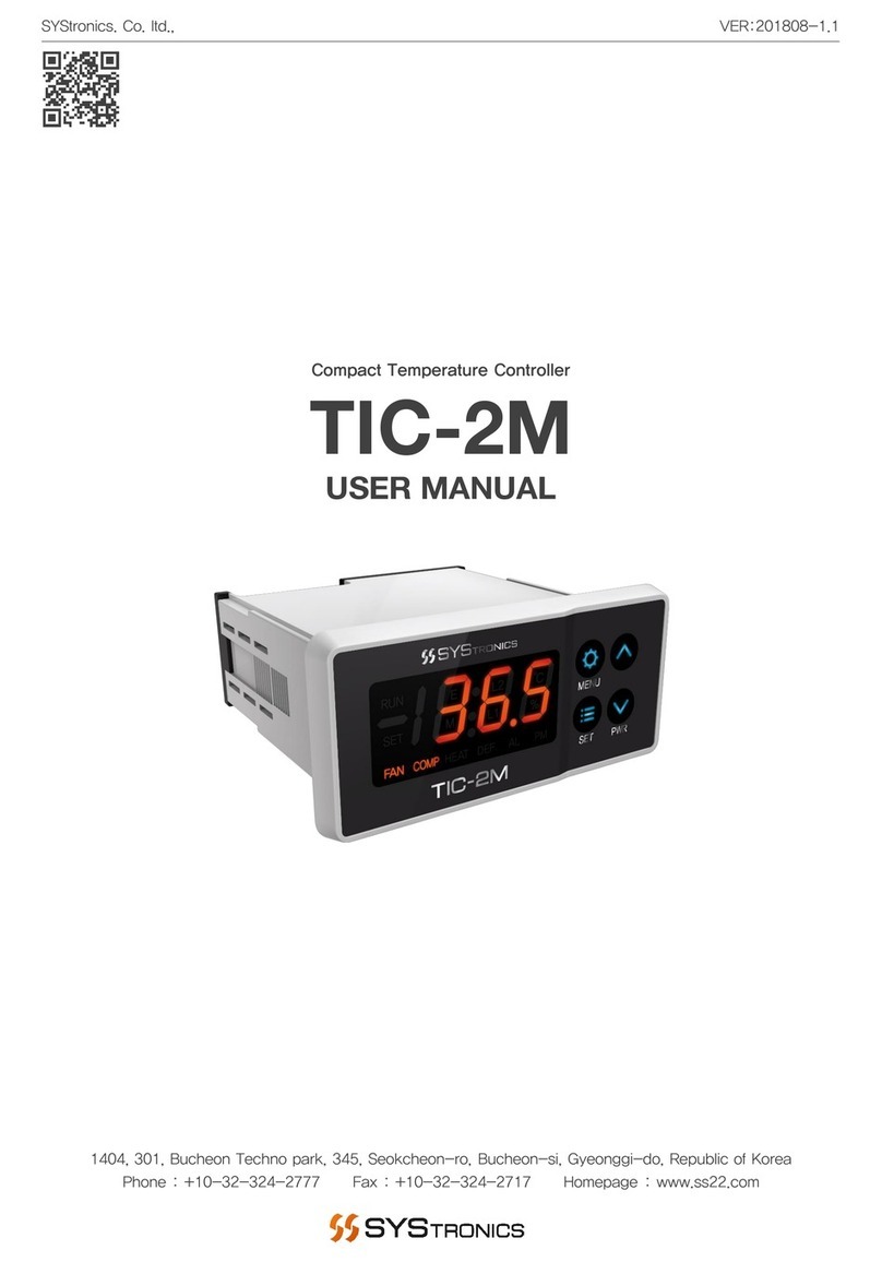
The TIC-4M Temperature Controller is a dedicated controller for cooling, refrigerating, cooling,
and heating operation, It is possible to use up to 4 ports of output and 1 ports of temperature
sensing port.You can also change the temperature monitoring port to input 2 ports by setting the
temperature monitoring port according to the setting conditions, and customize it to suit the site conditions. This
is a product that is equipped with a built-in communication 1port (up to 2 ports), which enables remote
monitoring and control.
·User setting function for various field conditions
· Digital Input 2 Port / Digital Output 4 Port
· RS-232 communication 1 port / NTC temperature monitoring port 3 port
· Application of coolers, heaters, units coolers, Showcase, etc.

TIC-4M MANUAL
4
Product Component
Controller
(1EA / TIC-4M)
Bracket
(2EA)
Normal type
NTC sensor
(1EA / SCTS-01)
Sensor Component
Advanced NTC
sensor
(1EA / SCTS-02)
High temperature
type NTC sensor
(1EA / SCTS-03)
Well type NTC
sensor
(1EA / SCTS-04)
(Choose one of the four sensor)

TIC-4M MANUAL
5
Product Specifications
Controller Specifications
Input Power 220VAC, 50/60Hz
Output Voltage 220VAC, 50/60Hz
Output Capacity 250VAC, 5A (Relay output)
Output Port 4 Port (Input power output)
Input Port 2 Port (Non-power source) / Changeable to temperature sensor input
Sensor Port 1 Port (NTC : 10K at 25℃ ±1℃)
Communication Port 1 Port (RS-485)
Operation Temperature -10 ~ 60℃ (Non condensation)
Operation Humidity 5 ~ 90% (Non condensation)
Storage Temperature -20 ~ 60℃ (Non condensation)
Controller Weight 282g

TIC-4M MANUAL
6
Sensor Specifications
Normal type cable sensor (SCTS-01)
Temperature Range -45 ~ 80℃ (NTC : 10K at 25℃ ±1%)
Sensor Weight 58g (Cable 3M standard)
Advanced type cable sensor (SCTS-02)
Temperature Range -45 ~ 105℃ (NTC : 10K at 25℃ ±0.5℃)
Sensor Weight 37.5g (Cable 3M standard)
High temperature type cable sensor (SCTS-03)
Temperature Range -45 ~ 150℃ (NTC : 10K at 25℃ ±1%)
Sensor Weight 64.5g (Cable 3M standard)
Well type cable sensor (SCTS-04)
Temperature Range -45 ~ 80℃ (NTC : 10K at 25℃ ±1%)
Sensor Weight 84g (Cable 3M standard)

TIC-4M MANUAL
7
Front view
Product Dimension
Top view
Side view
Front view Side view
Bracket Dimension
Controller Dimension
Display
42.5 x 20.3

TIC-4M MANUAL
8
Product Installation Method
1. After performing the work (72 mm x30 mm) in accordance with the specification, insert the controller into
the perforated holes.
2. Push the controller onto the wall and secure it firmly by pushing the bracket. When disconnecting, remove
the controller by separating it from the reverse side of the installation.

TIC-4M MANUAL
9
Product Wiring Diagram
L+ L- Sensor INPUT
+ - COM DI1 DI2
DO1 DO2 DO3 DO4 220VAC
Relay 220VAC / 5A
COMP
FAN DEF AL
circuit
breaker
R
N
220VAC
Set output function (DO3, DO4)
Input function,
input contact
setting possible
DEF
CP
RS-485
+ -

TIC-4M MANUAL
10
Operating Function
Name Image Contents
MENU key Return to Settings screen or return to previous screen.
Cancel the Optional menu data value.
SET key Select and save data value on the setup screen.
Alarm generated for 2 seconds by pressing for 2 seconds.
DEF / UP key Defrost ON / OFF.
Detailed menu movement and increased menu data value.
PWR / DOWN
key
Controller power ON/OFF.
Detailed menu movement and decreased menu data value.
Manual
Menu lamp
Engineer
Menu lamp
Comms.2
lamp
Comms.1
lamp
Temp.
lamp
Fan
lamp
Heater
lamp
Defrost
lamp
Alarm
lamp
Setting menu
lamp
Operating
Status lamp
Comp.
lamp

TIC-4M MANUAL
11
Setting Menu
Setting menu Explanation
Category Display Set.value Start value Contents
Setting
Temp.
Min. ~
Max. Temp. 20.0℃ The ability to set the desired temperature when operating the controller.
Cooling
Deviation 0.1~9.9℃ 2.0℃
Temperature variation in cooling operation and cooling point.
(Temperature of current climate setting temperature + cooling deviation)
Set temperature : 20℃ for 20℃ at 2℃. If the current temperature is at 22℃, the
cooling output will be kept at the temperature of 22℃.
Stop cooling output at the current temperature of 20℃ or below.
Heating
Deviation
OFF /
0.1~9.9℃OFF
The function of setting up the heater while operating the controller while
operating the controller.
OFF : Without auxiliary heater output.
Deviation setting : In each mode the current temperature is outputted to the set
temperature, if the temperature is lower than the heater deviation.
Setting menu Flow Chart
Run or stop display
Setting temperature
Deviation setting
Cooling deviation
Heating deviation
Change cooling deviation
Change Heating deviation
Change completed
Change completed
Change completed
Change setting temperature
Change Cancel
If you want to cancel the data change
In the menu, press the MENU key to
go to The previous menu.

TIC-4M MANUAL
12
Manual Menu
Manual menu Flow Chart
Fan mode
Comp. Restart
Heating Delay
Cooling Delay
Stop Delay
Power
Recovery
Equip. Number
Parameter Set.
Main Display
Cooling
Delay After
Defrosting
Fan Delay after
Defrosting
Defrosting
Time
Defrost Cycle
Defrost Mode
Defrost Set.
High Temp.
Alarm
Heater Alarm
Comp. Alarm
Alarm Set.
Comp.
Integration
Time
Fan Integration
Time
Integration
Time
High Temp. Alarm
Delay After Defrosting
Low Temp. Alarm
Heater Integration
Time
Push for more the 5sec.

TIC-4M MANUAL
13
Parameter Setting
Category Display Set.value Start value Contents
Equip.
Number 1~99 1 Set the address by setting the equipment number when using Remote
Supervisory Control.
Power
Recovery
OFF /
1~250sec 5 sec
Set the delay time for the blackout and the driver to operate the concurrent
controller.
Apply differential time to multiple equipment simultaneously to prevent loss of power
after returning to power.
OFF : No outage returns.
Stop
Delay
OFF /
1~250sec 60 sec
During shutdown of the equipment, all outputs are stopped sequentially
and the fan completes after the shutdown delay.
OFF : Output Off without stop delay.
Cooling
Delay 1~250sec 5 sec
Set the delay time for the compressor output to ON after the fan output has
been put on the cooling condition.
Heating
Delay 1~250sec 3 sec Set the delay period for the auxiliary heater output after the fan output is
turned on in the heating conditions.
Comp.
Restart
OFF /
1~250sec 20 sec Set standby delay setting for the Compton output to ON after the Comp
output is turned ON and OFF.
Fan Mode ON / Au ON
Set the air flow mode.
ON : The fan output is ON whenever the controller is in operation.
Auto:flower is driven in conjunction with the Compton output output output.
Manual Menu
Defrost Setting
Category Display Set.value Start value Contents
Defrost
Mode
OFF / FAN
/ H.t H.t
Set defrosting mode when defrosting.
OFF: Defrosting prohibited. / FAN: Only blower operates during defrost time after
driving cycle stop.
H.t: In defrosting condition, blower stops after pump down and defrost
heater output
is ON during defrost time.
Defrost
Cycle 1~24H 6H The cycle at which defrosting begins during operation
Defrosting
Time 1~60min 20 min Set defrosting time.
Fan Delay
after
Defrosting
OFF /
1~250sec 60 sec Setting delay time of blowing operation after defrost termination.
OFF: Fan output operation without delay after defrosting.
Cooling
Delay After
Defrosting
OFF /
1~250sec OFF Cooling operation delay time after defrost termination.
OFF: Cooling operation without delay after defrosting.
High Temp.
Alarm
Delay After
Defrosting
OFF /
1~250sec 30 sec Set the high alarm detection time after defrosting operation.
OFF: High temperature alarm is detected without delay after defrosting.

TIC-4M MANUAL
14
Manual Menu
Alarm Setting
Category Display Set.value Start value Contents
Comp.
Alarm
OFF /
1~250sec 5 sec
If the input to the COMP status input is detected or not detected during the
set time after the COMP output Set the detection time so that an alarm
occurs.
OFF: Alarm is not checked when set.
Heater
Alarm
OFF /
1~250sec 5 sec
If the input to the auxiliary heater status input is detected or set during the
set time after the auxiliary heater output If not, set the detection time to
trigger an alarm.
OFF: Alarm is not checked when set.
High Temp.
Alarm
OFF /
-40.0
~150.0℃
OFF
If the current temperature is higher than the high alarm set temperature, an
alarm is generated.
If the temperature is 1 degree below the set point of
the high temperature alarm, the alarm is cleared.
Heater operation stops when high temperature alarm occurs. / OFF: Alarm is not
checked when set.
Low Temp.
Alarm
OFF /
-40.0
~150.0℃
OFF
If the current temperature drops below the set low temperature alarm, an
alarm is generated. If the temperature rises 1 degree above the low \
temperature alarm setpoint, the alarm is cleared.
Cooling operation stops when low temperature alarm occurs. / OFF: Alarm is not
checked when set.
Integration Time
Category Display Contents
Fan, Comp.
Heater
Integration
Time
A function that can check the operation time of each port.
The display is expressed as 1 per 24 hours. (Eg display 2 = 48 hours
operation)
To delete the accumulated time, select the delete list and press the DEF
key for about 5 seconds to delete

TIC-4M MANUAL
15
Engineer Menu
Engineer menu Flow Chart
Parameter Setting
Main Screen
Input Contact 1
Input 2 Set.
Input 1 Set.
Output 4 Set.
Output 3 Set.
System Set.
Comp. Alarm Return
Alarm Set.
Temp. Filtering
Temp. Display
Interval
Display Set.
Input Contact 2
Temp. Sensor
Calibration
Lower Temp.
Setting
Upper Temp.
Setting
Push for more
the 5sec.
Push for more
the 5sec.

TIC-4M MANUAL
16
Engineer Menu
System Setting
Category Display Set.value Start value Contents
Output 3
Set. H.T / dEF Def Output The function to set the output of 3 port.
H.t (heater) / dEF (defrost)
Output 4
Set. AL / dEF AL Output The function to set the output of 4 ports.
dEF (defrost) / AL (comprehensive alarm)
Input 1 Set.
Fan / C.P
/ H.t / Def
/ rE
Def Input 1 A function that sets the alarm and status functions of the port.
FAn (fan) / C.P (compressor) / H.t (heater) / dEF (defrost) / rE (remote)
Input 2 Set.
Fan / C.P
/ H.t / Def
/ rE
rE Input 2 Function to set alarm and status function of port.
FAn (fan) / C.P (compressor) / H.t (heater) / dEF (defrost) / rE (remote)
Input
Contact 1 n.o / n.C n.C
Input 1 The function to set the input contact method of the port.
n.o: Operates normally when the corresponding input is detected.
n.C
: Normal operation should be performed if no corresponding input is detected
during operation.
Input
Contact 2 n.o / n.C n.C
Input 2 Set the input contact method of the port.
n.o: Operates normally when the corresponding input is detected.
n.C: Normal operation should be performed if no corresponding input is detected
during operation.
Alarm Setting
Category Display Set.value Start value Contents
Comp.
Alarm
Return
Su / Au Su Function to set Comp alarm release method.
Su (manual return) / Au (automatic return)
Display Setting
Category Display Set.value Start value Contents
Temp.
Display
Interval
0.1~
5.0 sec 0.5 sec The function to set the change time interval of the current control
temperature.
Temp.
Filtering
32 / 64 /
128 times 128 times Function to set temperature sensor sensitivity.
Temp.
Sensor
Calibration
-9.9~
9.9℃0.0℃
Function to correct the temperature value when the current temperature
differs from the actual temperature value in the room.
When the actual temperature is 20.0℃ and the display temperature is 18.0℃, if the
correction value is changed to 2.0℃, Converted to 20.0℃.
Upper
Temp.
Setting
-40.0~
150.0℃50.0℃Function to set upper limit temperature range of set temperature.
Lower
Temp.
Setting
-40.0~
150.0℃-40.0℃Function to set lower limit temperature range of set temperature.

TIC-4M MANUAL
17
Alarm List
Category Display Occur Cause Alarm Occurrence
Fan Alarm
An alarm occurs if fan alarm input is detected or
not detected according to input contact set
value for more than 5 seconds after fan output
(DO1). AI1,2 Alarm must be set to Fan.
All outputs stop when an alarm occurs. When
the alarm returns, the alarm is canceled and the
controller operates normally.
Comp.
Alarm
An alert is generated if the comp alarm input is
detected or not detected according to the input
contact set value during the alarm detection time
after the comp output (DO2).
Alarm must be set
to AI1,2 Comp.
Comp output is stopped when an alarm
occurs, The alarm is released upon return of the
operation alarm, Normal operation.
Heater
Alarm
An alarm is generated if the heater alarm input is
detected or not detected according to the input
contact set value during the alarm detection time
after the heater output (DO3). AI1,2 setting must
be set as heater to generate an alarm.
When an alarm occurs, the heater output is
stopped, The alarm is released upon return of the
operation alarm, Normal operation.
High Temp.
Alarm
Alarm occurs when control temperature is higher
than high temperature alarm during controller
operation.
Heating operation stops when an alarm occurs.
(Cooling operation operation) When the alarm is
returned, the alarm is released, and the controller
is in normal operation. (Current temp. ≤ high
temp. alarm -1 degree)
After defrosting operation, after defrosting, high
temperature alarm setting is detected.
Low Temp.
Alarm
Alarm occurs when control temperature is lower
than low temperature alarm during controller
operation.
Cooling operation stops when an alarm occurs.
(Heating operation operation) Alarm reset at alarm
return, controller normal operation. (Current
temp.e
≥ low temp. alarm +1 degree) Alarm release.
Control
Sesnor
Alarm
Alarm occurs when the control temperature
sensor is open or shorted.
All output stops when an alarm occurs. When
the alarm returns, the alarm is released and the
controller is in normal operation.
Remote
Detection
The remote operation is applied when the
controller is detected or not detected according
to the input contact set value for more than 2
seconds on the remote sensing input during
operation or stop.
Only when the controller is running Operation by
remote contact / stop.

TIC-4M MANUAL
18
Factory Reset
Push for more
the 2sec.
Notice : All settings on the controller
will return to their initial state.
Push for more
the 10sec.
Main Screen Factory Reset Menu
Factory Reset Complete
Factory Reset Cancel
Push for more
the 2sec.

TIC-4M MANUAL
19
The Service Guide is to protect the safety of the user and prevent property damage, so please read it carefully
and use it correctly. Please note that the warranty service does not apply to any case where the product is
used or handled arbitrarily without complying with the instructions specified in this Service Guide or manuals.
Use the product according to the specified method.
Regarding controller problems
Before submitting a service request, be sure to first read the details concerning the alarms or troubleshooting
checklist in the product manual of the corresponding model and follow the directions accordingly. The user
manual contains the troubleshooting procedure for the alarms and errors occurred to the controller.
What if the measures taken still don`t work?
Record the corresponding alarm or symptoms by taking a picture or video, and contact the equipment
manufacturer or supplier first. If this still doesn't resolve the problem, contact Systronics.
Service Charge
The warranty period for Systronics products is 1 year after purchase. (Warranty period for humidifier parts is
4,000 hours of operation time.) To ensure use of the product in a mint condition for a long period of time, be
sure to familiarize yourself with the precautions and instructions specified in the manual. For more information
on the service, refer to the product warranty statement in the user manual.
1. Please note that any problem/failure caused by the customer's inadvertent, unskilled handling and/or
negligence is not and will not be eligible for our warranty service.
2. This warranty service expires after 1 year of purchase. From that point on, your service request will be
charged for repairs or visits by our engineer.
3. Warranty service is not applicable to any failures caused by natural disasters (e.g., fire, flood, lightning, etc.).
Refund Policy
1. If you choose to return the product after 14 days have passed upon purchasing the product,you will have
to pay a refund fee even if you haven't used it.
2. Your refund request will be refused even when the request is made before 14 days pass upon purchasing
the product if you have installed or used the product.
Purchase Tip for Warranty Service
1. Before buying the product for warranty service, please listen carefully to the explanations offered by
Systronics and make a decision accordingly.
2. In principle, Systronics transacts with corporate clients. Therefore, restrictions may apply to the users at the
worksite who want to buy our product.
3. Let us know the information of the controller installed at the site (e.g., production no., program name,
Shipping date) through submission of an image or message form to quicken the order process.
Service Guide

TIC-4M MANUAL
20
Electronic control equipment has different operating characteristics from electromechanical equipment. Safety
instructions for the application, installation and maintenance of the electronic control unit, important differences
between the electrical and electronic control unit and the electric machine, and contents of the use for the
electric control unit. Due to these differences and the various uses of electronic equipment, the person
responsible for the application of this equipment must use and install this equipment only within the permitted
scope of application.
Overview of electrical noise control
Electrical noise can be caused by normal operation of components or components of the system due to
voltage spikes. The conduction mechanism may interfere with the operation of parts or elements of other
systems (noise interference), resulting in malfunction.
Generate noise source
1. Mechanically switched inductive loads generate strong noise intermittently. (MC, MCCB, etc.)
2. PWM drive power output generates severe continuous noise.
3. Switch mode DC power supply (SMPS) may continue to generate noise.
4. Noise source may occur due to contact switching.
Among the causes of the above noise sources, the noise that the system manufacturer can reduce is only
the contact switching noise.
Conduction noise
Electrical noise interferes with the normal operation of the equipment. In the case of electrical noise
conduction, noise may be directly conducted by the system power wiring, and may be emitted to the outside
through the wiring of the industrial control device (inverter).
ACㆍDC power cable installation
For AC·DC power installation, it is recommended to use junction, isolation, shielding and filter for power
supply and related wiring.
Motor power cable installation
If possible, do not extend the motor power cable. In principle, the cable between the drive and the motor can
not be used in extended connection. The universal reason for changing (extending) cables in the middle is
for applications that require flexible cables. Observe the following guidelines when handling the remaining
cables.
1. Do not detect different types of cables together. A transformer which is valid in HF is formed.
2. Cable length should be cut to fit the application.
3. If you can not cut the remaining cable, please arrange it in '8' or 'S' form. Never roll it round.
Precautions
Good example Good example Incorrect example
Table of contents
Other SYStronics Temperature Controllers manuals
Popular Temperature Controllers manuals by other brands

THORLABS
THORLABS TED4015 Operation manual

Honeywell
Honeywell PERFECT CLIMATE COMFORT CENTER owner's guide

Ekinex
Ekinex EK-ET2-TP user manual

MULTISPAN
MULTISPAN UTC-4203 operating manual

Lutron Electronics
Lutron Electronics LR-TEMP-FLSH installation instructions

Store It Cold
Store It Cold CoolBot Trouble error codes list

AKO
AKO AKO-D14412 installation instructions

Specac
Specac 523-211 quick start guide

Keysight Technologies
Keysight Technologies E2307A user guide

Auber Instruments
Auber Instruments WS-1510DPM Operation & instruction manual

Lowrance
Lowrance EP-80R Temp Installation and configuration instructions

Omron
Omron CJ Series Operation manual