I-134 Modular Temperature Controller E5ZN
Nomenclature
E5ZN-2
E5ZN-SDL
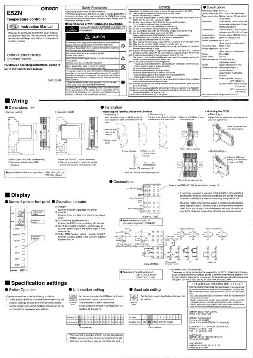
The following diagram shows the names and functions of the E5ZN-SDL parts for when it is connected to the E5ZN-2@@@@@@@.
Operation Indicators
POWER
Lights when power is turned ON.
ERROR
Lights when a fatal error (e.g., memory
error or sensor error) occurs.
SD/RD (Communications Operation)
Flashes during communications with the host.
OUT1 (Control Output 1)
Lights when the control output 1 is ON.
OUT2 (Control Output 2)
Lights when the control output 2 is ON.
SUB1 (Auxiliary Output 1)
Lights when the auxiliary output 1 is ON.
SUB2 (Auxiliary Output 2)
Lights when the auxiliary output 2 is ON.
POWER
ERROR
SD/RD
OUT1
OUT2
SUB1
SUB2
Unit Number Setting
Setting range of 0 to F allows up
to 16 Units to be set.
Baud Rate
No. 1 Display
Displays the PV or the type of
setting data.
No. 2 Display
Displays the target value, the
control variable, or the set value
for setting data (setting contents).
Up Key
Each time this key is pressed, the
value displayed in No. 2
Display increases. If it is held
down, the rate of increase
becomes faster.
It can also be used to move to the
next setting item.
Down Key
Each time this key is pressed, the
value displayed in No. 2
Display decreases. If it is held
down, the rate of decrease
becomes faster.
It can also be used to return to the
previous setting item.
Channel Key
Press this key to change the
channel number.
Copy Key
Press this key to read all the
settings from the Temperature
Controller to the Setting Display
Unit, or to write from the Setting
Display Unit to the Temperature
Controller.
UNIT Key
Press to switch the unit number.
Level Key and Mode Key
Press together to switch to protect mode.
Mode Key
Press this key to switch setting
data within the setting level.
Level Key
Press this key to switch setting
levels.
Unit/Channel Indicator
Indicates the unit number and
the channel number.
• SUB3 (Auxiliary Output 3)
Pulse output models: Always not lit.
Analog output models: Not lit when the
auxiliary output drops to 0% or lower.
Lit when the auxiliary output is above 0%.
• CMW (Communications Write Control)
Lights when communications write is permitted
and remains unlit when it is prohibited.
• STOP
Lights when operation stops. Lights for an
event or when RUN/STOP is set to STOP
during control. Remains unlit at other times.
• SUB1, SUB2 (Auxiliary Output 1, Auxiliary
Output 2)
Light when the auxiliary output 1 or the
auxiliary output 2 functions are ON.
• OUT1, OUT2 (Control Output 1, Control
Output 2)
Light when the control output 1 or the control
output 2 functions are ON.
• These indicators indicate the terminal
operations for the E5ZN-2@@@@@@@.
Operation Indicators Temperature Unit
Displayed when the display unit for setting
data is temperature. The display is
determined by the setting for temperature unit,
with either “°C” or “°F” displayed accordingly.
• SUB4 (Auxiliary Output 4)
Pulse output models: Always not lit.
Analog output models: Not lit when the
auxiliary output drops to 0% or lower.
Lit when the auxiliary output is above 0%.
