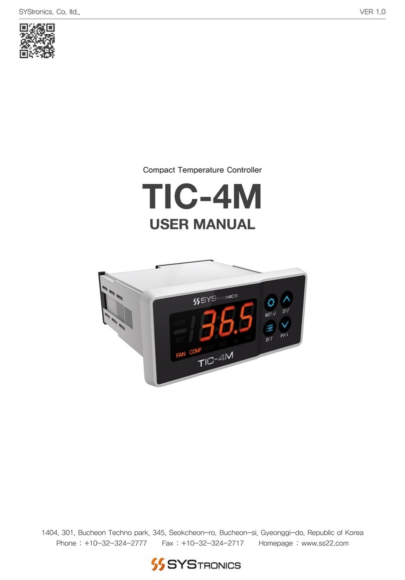
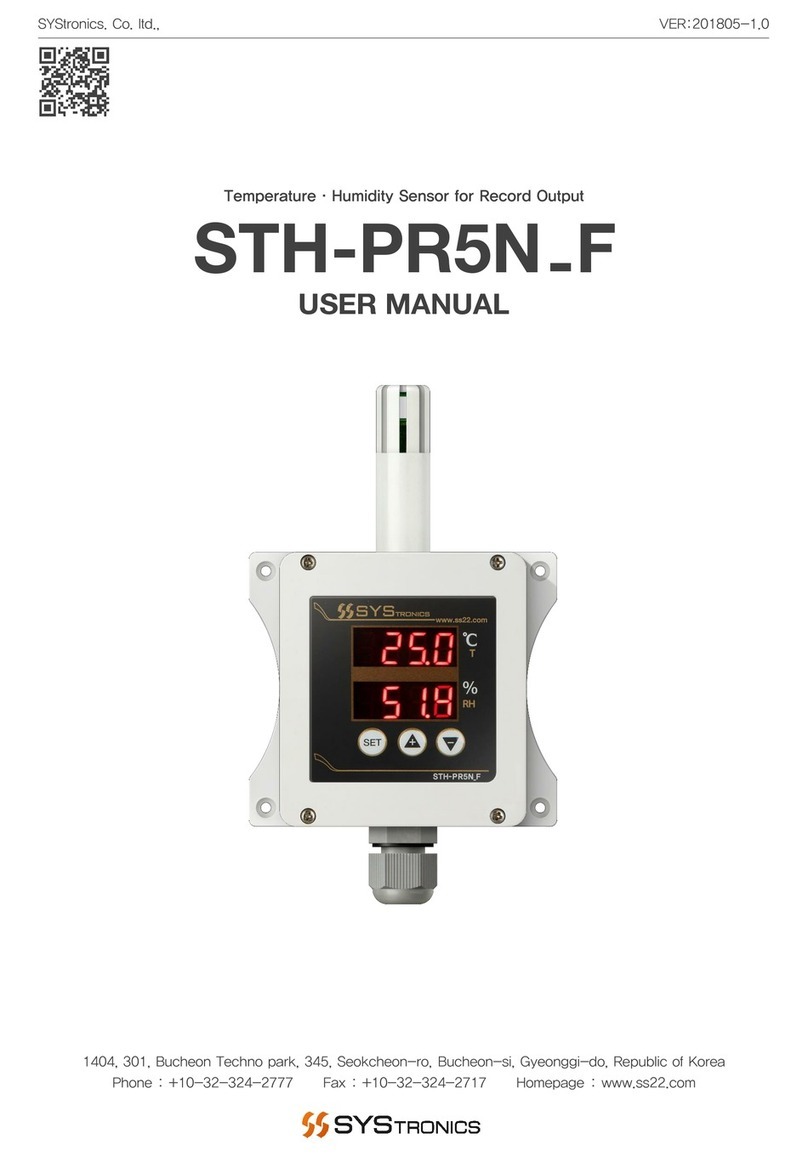
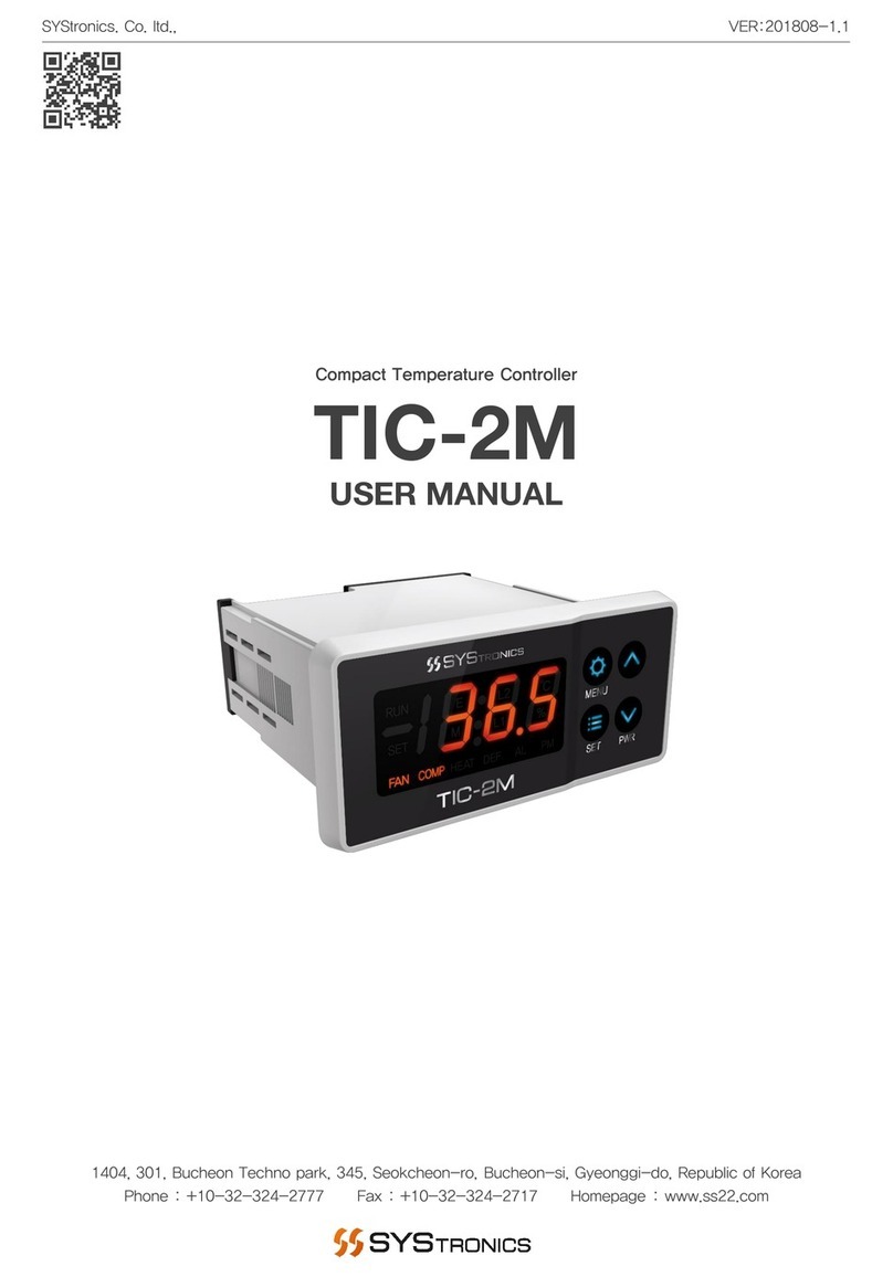
SYStronics STH-PD5N F User manual

STH-PD5N_F MANUAL
1
USER MANUAL
Duct Type Temperature·Humidity Sensor for Record Output
VER:201805-1.0
STH-PD5N F
-
SYStronics. Co. ltd.,
1404, 301, Bucheon Techno park, 345, Seokcheon-ro, Bucheon-si, Gyeonggi-do, Republic of Korea
Phone : +10-32-324-2777 Fax : +10-32-324-2717 Homepage : www.ss22.com

STH-PD5N_F MANUAL
2
Be sure to read and ensure that your safety precautions are used to protect your safety and prevent property
damage. We shall not accept any liability for any loss caused by the use or carelessness caused by the use
or handling of this manual.
Warning
If this product is not intended as a safety device, use a double safety device for fear of accidents, damage of
critical peripheral equipment, and equipment that is feared to cause extensive property damage.
Safety instructions
1. Be sure to check the equipment after disconnecting mains.
2. Do not disassemble and repair this product ; it is not possible to manufacture any product.
3. Do not spray water directly or clean it with benzene, jazzy, or alcohol.
Notes on the environment
Do not install this product in the following locations and environments :
1. Places directly exposed to mechanical vibration or shock
2. Places exposed to corrosive gases or combustible gases
3. Position directly exposed directly to direct sunlight
4. Places affected by electromagnetic waves
5. Places where high temperature or humidity is high (sites with over 85 % of ambient humidity)
6. Places where dust and salt are plentiful
Precautions on installation
1. Make sure that the installation work is related to the installation or qualified personnel only.
2. Do not place any device or wiring that caused noise (NOISE) near the product.
3. Avoid near heating apparatus.
4. Disconnect all appliances (OFF) after disconnecting them from the wiring.
5. Do not work with wet hands. Risk of electric shock.
6. Install and use the method described in the User Manual as instructed in the Instructions for Use.
7. Do not turn on (power on) prior to the connection between the unit of manufacture of this unit.
8. Do not use any load exceeding the opening and closing capacity of the output contacts.
Immunity condition
1. In addition to the contents set forth herein, no warranties and responsibilities shall be made regarding this
product.
2. Whether or not this product is likely to be unforeseen defects and natural disasters due to the use of this
product, the user or the third person We shall not be held liable for any indirect damage.
Precautions

STH-PD5N_F MANUAL
3
Product Overview
STH-CD5N_F is equipped with temperature·humidity sensor elements. This sensor is designed
for duct installation. It is easy to use in the field where the temperature and humidity need to be precisely
monitored such as the thermo-hygrostat, low-temperature warehouse. And It is a product that can
output temperature and humidity data as analog signals. In addition, by positioning the FND and
buttons on the front, you can easily control the temperature and humidity monitoring and setting of industrial
sites and equipment.
· Digital temperature·humidity sensor
·Monitoring with front panel FND
·Designed for air duct
·Temperature·humidity data analog signal output

STH-PD5N_F MANUAL
4
Product Component
Duct bracket
Aluminum
Body fastening screw 4EA
M3 ×8
FND Display
4 Digit FND x 2EA
Control unit
Button Key
Sensor sintering
Nickel Plating
Detailed Structure of Product
Sensor probe
Aluminum
Sensor body
ABS
Cable grand
PG9
Duct fastening screw 4EA
M4 ×6

STH-PD5N_F MANUAL
5
Product Specifications
Temperature Sensor Specifications
Measuring Range -20.0 ~ 80.0℃
Accuracy ±0.3℃ (Max ±0.4℃)
Resolution 0.015℃
Reaction Time 2.0 sec
Controller Specifications
Input Power DC 24Vdc
Power Consumption 75mA / 1.8W (at 24Vdc)
Operating Temp. -20 ~ 80℃ (Non condensing)
Operating Humi. 5 ~ 95% (Non condensing)
Storage Temp. 0 ~ 60℃ (Non condensing)
Body Weight 324.5g (Cable basic 3M / Including probe)
Bracket Weight 54.5g (Meterial : Aluminum)
Cable Weight 94.0g
Cable Length Basic 3M (Can be changeable / AWG standard : More than 20)
Humidity Sensor Specifications
Measuring Range 0 ~ 100% RH
Accuracy ±3% RH (Max ±4.5% RH)
Resolution 0.01% RH
Reaction Time 8.0 sec
Temperature Accuracy Graph
0.0
0.5
1.0
1.5
-40 -20 020 40 60 80 100 120
Temperature (%)
±
±
±
±
T (℃)
0
1
2
3
4
5
6
7
8
010 20 30 40 50 60 70 80 90 100
Relative Humidity (%RH)
±
±
±
±
±
±
±
±
±
RH (%RH)
Humidity Accuracy Graph
Maximal Tolerance
Typical Tolerance
Maximal Tolerance
Typical Tolerance

STH-PD5N_F MANUAL
6
Top view
Front view Side view
Duct bracket
Product Dimension (Unit : mm)

STH-PD5N_F MANUAL
7
Product Installation Method
1. Perform perforation (Ø16.5) according to the duct installed the sensor. Please take into consideration the
depth at which the sensor probe is to be inserted and the installation environment.
2. Position the protruded part of the duct bracket so that it faces outward and fix it with 4 duct fixing screws
(M4).

STH-PD5N_F MANUAL
8
Product Installation Method
3. Duct bracket Insert the sensor probe into the hole at the required depth and direction, and fix it firmly to
the bracket using the sensor fixing screw (MX).

STH-PD5N_F MANUAL
9
Product Wiring Method
Wiring Precautions
1. When wiring, check the polarity and connect the wiring correctly.
2. To avoid malfunction, avoid the use of the same conduit or the same duct for the wiring of high-voltage
lines and power lines and sensors.
3. When changing the supplied cable, connect the communication shield cable of AWG20 or higher standard.
Wiring Diagram
Color Contents Function
RED Sensor power supply (DC 24V / + ) Power supply terminal
GREEN Sensor power supply (DC 24V / - )
WHITE Temperature / humidity record output common terminal (- Terminal)
Record output terminalBLUE Temperature record output terminal (+ Terminal)
BLACK Humidity record output terminal (+ Terminal)
HUMI (+)
TEMP (+)
GND (-)
PWR (-)
PWR (+)
PWR (+)
PWR (-)
GND (-)
TEMP (+)
HUMI (+)

STH-PD5N_F MANUAL
10
How to set up the product
Notes on Setting
1. Since it is set as follows inside the sensor when opening the front cover, refer to it when connecting.
2. When shipped from the factory, it will be shipped with the specifications requested in advance. Please
refer to the following documents when changing the analog output specifications.
Image
Item TEMP: 4~20mA
HUME : 4~20mA
TEMP : 4~20mA
HUMI : 1~5V
TEMP : 1~5V
HUMI : 4~20mA
TEMP : 1~5V
HUMI : 1~5V
How to Set the Output
TEMP HUMI TEMP HUMI TEMP HUMI TEMP HUMI

STH-PD5N_F MANUAL
11
Operating Function
Name Image Contents
Setting Button
Enter setting screen. (Hold for 2 seconds)
Go to settings menu. (Short press)
Save setting value and return to monitoring screen. (Hold for 2
seconds)
Increase Button Increase setting value. (Short or long press)
Decrease Button Decrease setting value. (Short or long press)
Temp. Display
Humi. Display
Decrease
Button
Increase
Button
Setting
Button
Function of the Control Panel
Structure of Operation Part

STH-PD5N_F MANUAL
12
Setting Screen Flow Chart
Lower Limit Temp.Humi. Record Output
Upper Limit Temp.Temp. Record Output
Lower Limit Humi.Humi. Calibration
Upper Limit Humi.Temp. CalibrationMain Display
Hold for 3 seconds
Hold for 3 seconds
Save set value and return to
the main screen
Pressing the setting button for 3
seconds on each setting screen
save the setting value and return
to the main screen.
Go to the menu below
Pressing the setting button for 1
second on each setting screen
moves to the menu below.

STH-PD5N_F MANUAL
13
Setting Screen
Setting Operation
Name Image Contents
Setting Button Go to settings menu. (Short press) / Save setting value and return
to monitoring screen. (Hold for 2 seconds)
Increase Button Increase setting value. (Short or long press)
Decrease Button Decrease setting value. (Short or long press)
Item
Set. Value
Start Value
Contents
Temp.
Calibration
-
9.9 ~
9.9℃ 0℃
Temperature
compensation function when current temperature differs
from
actual room temperature value.
If the temperature of the room is 20.0 ℃and the temperature of the monitor is 18.0℃,
changing the set value to 2.0 ℃will convert the current temperature value of the
monitor to 20.0 ℃.
Humi.
Calibration
-9.9
~
9.9℃ 0%
Humidity
value correction function when the current humidity is different
from
the actual humidity value inside the room.
If the room humidity is 45.0% and the monitor humidity is 43.0%, changing the
setting value to 2.0% will convert the current humidity value of the monitor to 45.0%.
Temp.
Record
Output
0 ~
100℃0℃
As a temperature record output test, it can be confirmed that the temperature
record output is normally output from 0.0% to 100%.
Humi.
Record
Output
0 ~
100% 0%
As a humidity record output test, it can be confirmed that the humidity record
output is normally output from 0.0% to 100%.
Lower
Limit Temp.
-50 ~
100℃ -20℃
Set
the operating temperature range of the temperature record.
When the lower limit temperature value is set to -50℃and the upper limit temperature
value is set to 50℃, the operating temperature range is set to -50 ~50℃, the setting
range is divided into 100 equal parts and output based on that temperature value.
A value of 0% is output when the current temperature is -50℃/50%at 0℃/100%at 50℃.
Upper
Limit Temp.
-50 ~
100℃ 60℃
Lower
Limit
Humi
.
0 ~
100% 0%
Set
the operating humidity range of the humidity record.
When the lower limit humidity value is set to 0% and the upper limit humidity value is
set to 100%, the operating humidity range is set to 0 ~ 100%, the setting range is
divided into 100 equal parts and output based on that humidity value.
A value of 0% is output when the current humidity is 0% / 50%at 50% / 100%at 100%.
Upper
Limit
Humi
.
0 ~
100% 100%
Setting Screen Description
Monitor Set. Value
Current output (4 ~ 20mA)
Voltage output (1 ~ 5V)
0% 4mA 1V
50% 12mA 3V
100% 20mA 5V
Monitor Set. Value
Current output (4 ~ 20mA)
Voltage output (1 ~ 5V)
0% 4mA 1V
50% 12mA 3V
100% 20mA 5V

STH-PD5N_F MANUAL
14
Alarm Screen
Alarm Screen Description
Item Setting Range Causes Solution
Temp.
Sensor
Check
Alarm occurs when the temperature
sensor is Short or Open.
1
. Confirm that you are using the
temperature measurement within
the
possible range.
Humi.
Sensor
Check
Alarm occurs when the humidity
sensor is Short or Open.
1
. Confirm that you are using the
humidity measurement within the
possible range.
2
.If it is higher than the current
humidity
or if it is impossible to measure, dry
the sensor in a well-ventilated area
for a certain period of time and reco-
nnect it.

STH-PD5N_F MANUAL
15
The Service Guide is to protect the safety of the user and prevent property damage, so please read it carefully
and use it correctly. Please note that the warranty service does not apply to any case where the product is
used or handled arbitrarily without complying with the instructions specified in this Service Guide or manuals.
Use the product according to the specified method.
Regarding controller problems
Before submitting a service request, be sure to first read the details concerning the alarms or troubleshooting
checklist in the product manual of the corresponding model and follow the directions accordingly. The user
manual contains the troubleshooting procedure for the alarms and errors occurred to the controller.
What if the measures taken still don`t work?
Record the corresponding alarm or symptoms by taking a picture or video, and contact the equipment
manufacturer or supplier first. If this still doesn't resolve the problem, contact SYStronics.
Service Charge
The warranty period for SYStronics products is 1 year after purchase. (Warranty period for humidifier parts is
4,000 hours of operation time.) To ensure use of the product in a mint condition for a long period of time, be
sure to familiarize yourself with the precautions and instructions specified in the manual. For more information
on the service, refer to the product warranty statement in the user manual.
1. Please note that any problem/failure caused by the customer's inadvertent, unskilled handling and/or
negligence is not and will not be eligible for our warranty service.
2. This warranty service expires after 1 year of purchase. From that point on, your service request will be
charged for repairs or visits by our engineer.
3. Warranty service is not applicable to any failures caused by natural disasters (e.g., fire, flood, lightning, etc.).
Refund Policy
1. If you choose to return the product after 14 days have passed upon purchasing the product, you will have
to pay a refund fee even if you haven't used it.
2. Your refund request will be refused even when the request is made before 14 days pass upon purchasing
the product if you have installed or used the product.
Purchase Tip for Warranty Service
1. Before buying the product for warranty service, please listen carefully to the explanations offered by
SYStronics and make a decision accordingly.
2. In principle, SYStronics transacts with corporate clients. Therefore, restrictions may apply to the users at the
worksite who want to buy our product.
3. Let us know the information of the controller installed at the site (e.g., production no., program name,
Shipping date) through submission of an image or message form to quicken the order process.
Service Guide

STH-PD5N_F MANUAL
16
Table of contents
Other SYStronics Temperature Controllers manuals
Popular Temperature Controllers manuals by other brands

Haswill
Haswill AL8010F+ user manual

La Crosse Technology
La Crosse Technology Tomorrow's Weather Today TX28U manual

Phoenix
Phoenix DryTAG RH installation instructions

PSG
PSG DC10 operating manual

Masimo
Masimo Radius T quick start guide

Johnson Controls
Johnson Controls TE-6800 Series installation guide