manuals.online logo
Brands
  1. Home
  2. •
  3. Brands
  4. •
  5. SyxthSense
  6. •
  7. Control Unit
  8. •
  9. SyxthSense SFT Series Dimensions

SyxthSense SFT Series Dimensions

Online store: www.syxthsense.com
Enquiries: T: 0844 840 3100 F: 0844 840 3200 PS TH6.95 - 1/6
SFT Series Digital Fan Coil Unit
Controllers
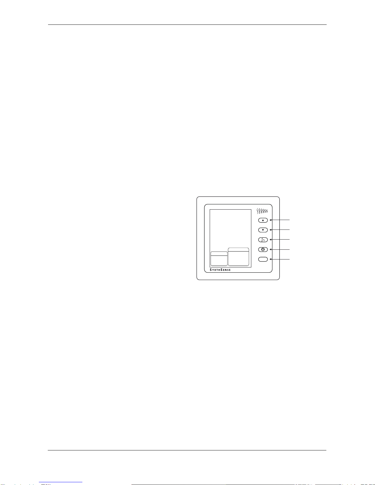
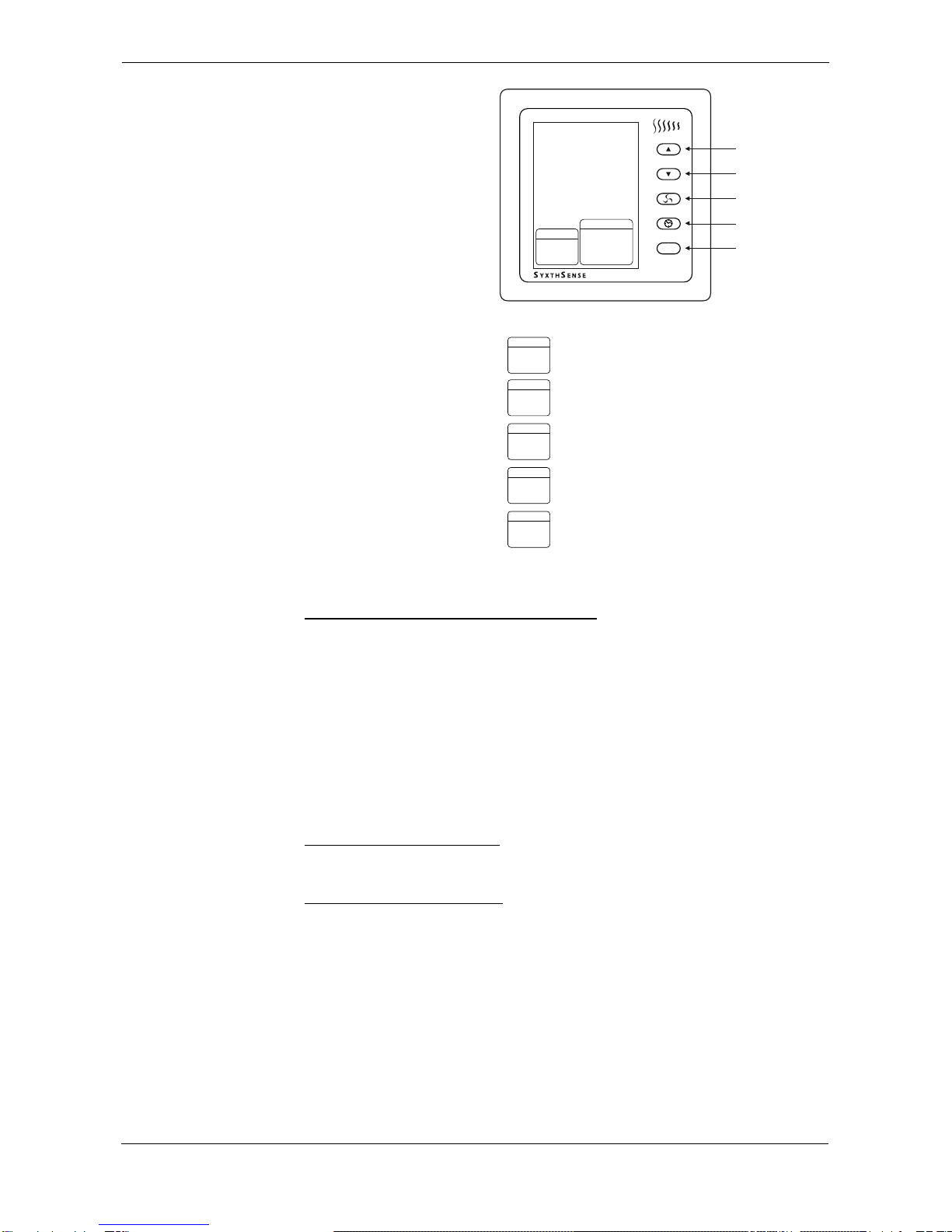
SFT series are elegant fan coil unit controllers with a large clear
LCD screen. The units are operated with five high quality buttons.
The SFT range of fan coil unit controlers is available with a range
of models to suit most applications.
The SFT controllers can be extensively applied for residential,
industrial and commercial environments. The Controllers have
switching rating of up to 16A 230V making them suitable for both
wet systems and electrical heating systems.
Depending on the model, the SFT controllers can operate using
internal or external sensor and have 7 day time programme.
The SFT range has RS485 communication capability making them
ideal for all commercial applications.
Features
• 24VAC/110VAC/230VACPower Supply (depend on models)
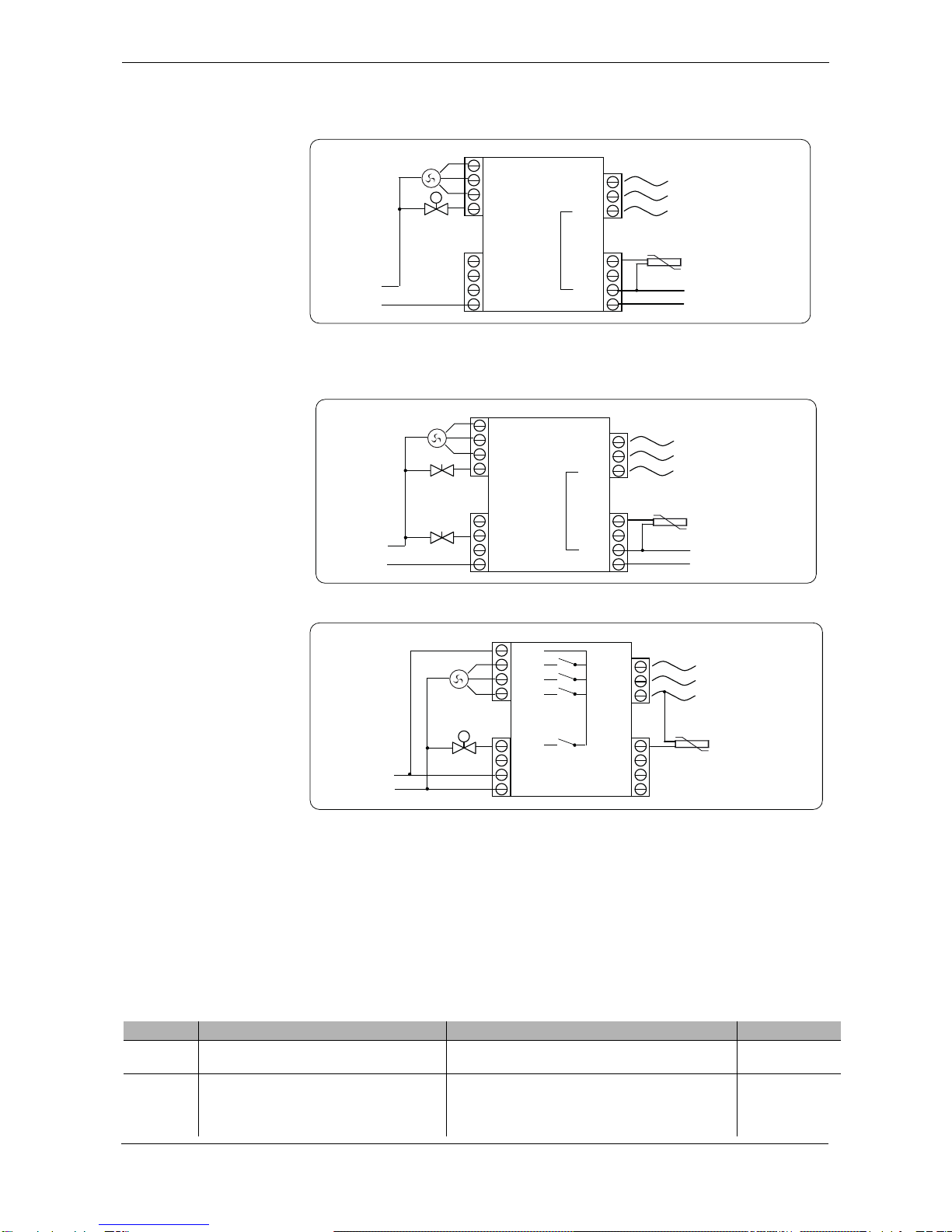
• 2-Pipe FCU Systems
• 4-Pipe FCU Systems
• Large Digital Display with Back-Light
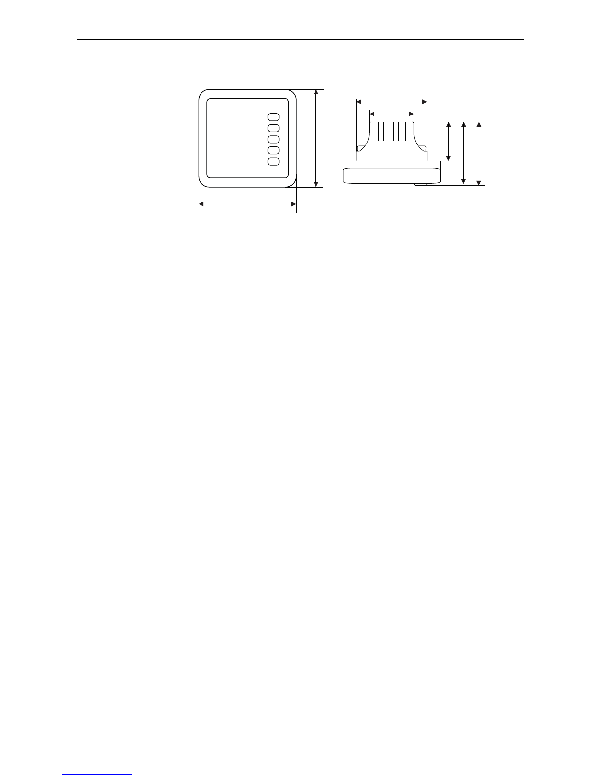
• Flush Mounted for Sophisticated Look
• 5+2/7 Day Time Programme ("P"-models)
• Inside Temperature Display
• Celcius / Fahrenheit Display
• 12/24 Hour Time Mode
• Auto/Manual Fan Speed Programmable
Product sheet TH6.95
Controller Type SFT
Model Type Model Description
SFT-A24-505 2-Pipe Fan Coil Unit Controller, 24Vac Power, Heating or Cooling
(configurable), Modbus Communication
SFT-A24-506 2-Pipe Fan Coil Unit Controller, 24Vac Power, Heating or Cooling
(configurable), 3-Speed Fan Control, Modbus Communication
SFT-A24-P505 2-Pipe Fan Coil Unit Controller, 24Vac Power, Heating or Cooling
(configurable), Modbus Communication, Time Clock
SFT-A24-P506 2-Pipe Fan Coil Unit Controller, 24Vac Power, Heating or Cooling
(configurable), 3-Speed Fan Control, Modbus Communication, , Time Clock
SFT-A110/230-505 2-Pipe Fan Coil Unit Controller, 110Vac/230Vac Power, Heating or Cooling
(configurable), Modbus Communication
SFT-A110/230-506 2-Pipe Fan Coil Unit Controller, 110Vac/230Vac Power, Heating or Cooling
(configurable), 3-Speed Fan Control, Modbus Communication
SFT-A110/230-P505 2-Pipe Fan Coil Unit Controller, 110Vac/230Vac Power, Heating or Cooling
(configurable), Modbus Communication, , Time Clock
SFT-A110/230-P506 2-Pipe Fan Coil Unit Controller, 110Vac/230Vac Power, Heating or Cooling
(configurable), 3-Speed Fan Control, Modbus Communication, Time Clock
SFT-A24-605 4-Pipe Fan Coil Unit Controller, 24Vac Power, Heating and Cooling, Modbus
Communication
SFT-A24-606 4-Pipe Fan Coil Unit Controller, 24Vac Power, Heating and Cooling,
3-Speed Fan Control, Modbus Communication
SFT-A24-P605 4-Pipe Fan Coil Unit Controller, 24Vac Power, Heating and Cooling, Modbus
Communication, Time Clock
SFT-A24-P606 4-Pipe Fan Coil Unit Controller, 24Vac Power, Heating and Cooling,
3-Speed Fan Control, Modbus Communication, , Time Clock
Technical Data Power Supply A24 Models: AC24V ± 10%z or DC24V
A110/230 Models: AC110V-AC240V
SyxthSense Ltd
Copyright © 2012 SyxthSense Ltd. All rights reserved - 02/2012
PS TH6.95 - 2/6
Online store: www.syxthsense.com
Enquiries: T: 0844 840 3100 F: 0844 840 3200
Operating Instructions
(2-Pipe FCU Controller) MODE Button
Pressing the MODE button the unit
operating mode can be changed.
The available options are: HEAT,
VENT, COOL, OFF.
In HEAT position the controller
operates in heating mode. When
the temperature drops below the
setpoint the valve output is
switched ON.
In COOL position the controller
operates in cooling mode. When
the temperature increases above
the setpoint the valve output is
switched ON.
In VENT position the unit only runs the fan. It is not possible to change the setpoint or set the fan to
operate in automatic mode. The required fan speed(LOW/MED/HIGH) is set by pressing the FAN
button.
In OFF position the FAN and VALVE outputs are switched OFF. The controller provides low limit frost
protection.
Temperature Setting
When the controller is ON, press UP or DOWN buttons to set the desired temperature.
Fan Speed Selection
Press the FAN button until the required fan speed is selected. In AUTO position the fan speed is
modulated automatically.
The available options are LOW, MED, HIGH, AUTO
Setting Controller Time (only available in P-models)
SETTING Controller TIME
When the Controller is ON, press the CLOCK button. The hours will flash. Press UP or DOWN buttons
to set the desired hour.
Press CLOCK button again to set the minutes (time). The minutes will flash. Press UP or DOWN
buttons to set the desired minutes.
Press CLOCK icon gain, and Weekday will flash. Then press UP or DOWN buttons to set the correct
weekday.
Fan Speed Output 3 x 3(1)A 230VAC SPST Relays
Control Valve 1 x 230VAC SPST Relay
Measurement Range 5..95°C
Accuracy 0.5°C/F
Working Temperature 0..70°C
Setpoint Range 5 to 95°C/F
Terminals Max 2.5 mm2(min 0.5mm2)
Communication RS485 Modbus RTU, up to 63 devices (logical address range 1..255)
(extended range available on special order)
Modbus Settings 9600 baud, 8 Data Bits, None Parity, 1 Stop Bit
Color White with glass panel
Housing ABS Flame Retardant
Mounting Flush Mounting (wall mounting using a separate box)
Dimensions W86 x H86 x D14.5 mm
Weight 0.15kg
Environmental Conditions Operating Temp 0..+50°C
Humidity Limits 0..95% rH non-condensing
Storage Temp -20..+50°C, Humidity <95% rH
Environmental
Standards IEC721-3-3, Climatic Conditions Class 3K5
EN 60730
UP button
DOWN button
FAN button
CLOCK button
MODE button
M
SYSTEM
FAN
LOW
MED
HIGH
AUTO
HEAT
COOL VENT
SyxthSense Ltd
Copyright © 2012 SyxthSense Ltd. All rights reserved - 02/2012
PS TH6.95 - 3/6
Online store: www.syxthsense.com
Enquiries: T: 0844 840 3100 F: 0844 840 3200
Operating Instructions
(4-Pipe FCU Controller) MODE Button
Pressing the MODE button the unit
operating mode can be changed.
The available options are: AUTO
(HEAT or COOL), HEAT, VENT,
COOL, OFF.
In AUTO position the controller
operates in automatic heating or
cooling mode depending on the
relevant setpoints and the
measured temperature.
In HEAT position the controller
operates in manual heating mode.
When the temperature drops below
the HEATING setpoint the valve
output is switched ON.
In COOL position the controller
operates in cooling mode. When
the temperature increases above
the COOLING setpoint the valve
output is switched ON.
In VENT position the unit only runs
the fan. It is not possible to change
the setpoint or set the fan to
operate in automatic mode. The
required fan speed
(LOW/MED/HIGH) is set by
pressing the FAN button.
In OFF position the FAN and
VALVE outputs are switched OFF.
The controller provides low limit frost protection.
Temperature Setting
WHEN IN AUTOMATIC HEATING OR COOLING MODE
When the controller is in automatic HEAT or COOL mode, press UP or DOWN buttons to set the
HEATING AND COOLING temperature setpoints. First the current active setpoint is displayed. After
approx 3 seconds the controller shows the not active setpoint.
For Example: If the controller is is in AUTO HEAT mode, when UP and DOWN arrows are pressed
text HEAT is displayed together with the HEATING setpoint. Pressing UP and DOWN arrows allows
the heating setpoint to be altered. Once the required HEATING setpoint has been set after approx 3
seconds the COOLING setpoint is displayed and it can be altered by pressing UP and DOWN arrows.
In the AUTO COOL mode the COOLING setpoint is displayed first.
Note: If the COOLING setpoint is set below the HEATING setpoint, the HEATING setpoint is
automatically reset to COOLING SETPOINT - 1°C to prevent simultaneous heating and cooling.
Similarly if the HEATING setpoint is above the COOLING setpoint the COOLING setpoint is rest to
HEATING setpoint + 1°C.
WHEN IN MANUAL HEATING MODE
When the controller is in manual HEAT mode, press UP or DOWN buttons to set the HEATING
temperature setpoint. COOLING setpoint is not displayed.
WHEN IN MANUAL COOLING MODE
When the controller is in manual COOL mode, press UP or DOWN buttons to set the COOLING
temperature setpoint. HEATING setpoint is not displayed.
Fan Speed Selection
Press the FAN button until the required fan speed is selected. In AUTO position the fan speed is
modulated automatically.
The available options are LOW, MED, HIGH, AUTO
Setting Controller Time (only available in P-models)
SETTING Controller TIME
When the Controller is ON, press the CLOCK button. The hours will flash. Press UP or DOWN buttons
to set the desired hour.
Press CLOCK button again to set the minutes (time). The minutes will flash. Press UP or DOWN
buttons to set the desired minutes.
UP button
DOWN button
FAN button
CLOCK button
MODE button
M
SYSTEM
FAN
LOW
MED
HIGH
AUTO
HEAT
COOL VENT
AUTO
SYSTEM
COOL
AUTO
System Modes
SYSTEM
HEAT
AUTO
SYSTEM
COOL
SYSTEM
HEAT
Automatic Cooling Mode
Automatic Heating Mode
SYSTEM
VENT
Manual Cooling Mode
Manual Heating Mode
Manual Ventilation Only Mode
SyxthSense Ltd
Copyright © 2012 SyxthSense Ltd. All rights reserved - 02/2012
PS TH6.95 - 4/6
Online store: www.syxthsense.com
Enquiries: T: 0844 840 3100 F: 0844 840 3200
Press CLOCK icon gain, and Weekday will flash. Then press UP or DOWN buttons to set the correct
weekday.
Wiring Details - 24VAC
2-Pipe FCU Versions
WARNING: The electrical wiring is to be carried out by qualified electricians and is required to
comply with the local wiring and electrical regulations.
Wiring Details - 24VAC
4-Pipe FCU Versions
Wiring Details - 110/230VAC
Versions
Advanced Parameter
Settings Advanced parameter settings are used to re-configure the SFT controller operation. Exact settings
available depend on the model.
To enter the configuration mode, switch the controller OFF (from MODE button). Then press the FAN
button continuously up to 10 seconds to display the first of the configuration paratemers. To adjust the
setting press UP or DOWN button until the required setting is displayed.
To advance to the next parameter press FAN button again. Continue until all required parameters
have been set. At any time the configuration can be exited by pressing the MODE button, and the
normal operation resumes.
WARNING: Use care when changing the advanced configuration parametes as these affect the
operation of the thermostat.
0V
B
A
L
0V COMMON
L
A
B
RS Remote Sensor*
RS-485
Modbus
* Depending on model
SFT CONTROLLER
230 VAC
M
Valve
LOW
MED
HI
VAL
N 0V
24V
AC24VN / DC24V 0V
AC24VL / DC24V 24V
0V
B
A
L
0V COMMON
L
A
B
ST1 Remote Sensor*
RS-485
Modbus
* Depending on model
SFT CONTROLLER - 4-PIPE
230 VAC
24 VAC
Cooling Valve
LOW
MED
HI
CLG/NO
N 0V
24V
AC24VN / DC24V 0V
AC24VL / DC24V 24V
ST2
CLG/NC
HTG/NO
HTG/NC
Heating Valve
GND
B
A
N
0V
L
N
A
B
ST1 Remote Sensor*
RS-485
Modbus
* Depending on model
SFT CONTROLLER
230 VAC
M
Valve
LOW
MED
HI
VAL
ST2
110 VAC
L
L
SwL
SwL
SwL
SwL R1
R2
R3
R4
Parameter Parameter Description Available Settings Default
PS Thermostat Operation when power is
Applied 0 - Thermostat OFF when power is applied
1 - Thermostat ON when power is applied 1
HL Highest Setpoint Allowed 5..35
(The value of the highest setpoint that a user can
program into the SFT. Any setpoint attempted to be
higher than this setting willbe returned to this value)
35
SyxthSense Ltd
Copyright © 2012 SyxthSense Ltd. All rights reserved - 02/2012
PS TH6.95 - 5/6
Online store: www.syxthsense.com
Enquiries: T: 0844 840 3100 F: 0844 840 3200
Modbus Networking
Diagram
CL Lowest Setpoint Allowed 5..35
(The value of the lowest setpoint that a user can
program into the SFT. Any setpoint attempted to be
lower than this setting willbe returned to this value.)
5
CF Unit Selection C - Celcius display enabled
F - Fahrenheit display enabled C
RC Room Temperature Offset +/-10°C 0
TC 12/24 Time Mode 12 - 12 Hour Clock
24 - 24 Hour Clock 12
PP Controller Mode 2P or 4P
2-pipe or 4-pipe application. Select always 2P mode. 4P
SL Sleep Mode 0 - Disabled
1 - Enabled
FA Fan Mode Selection DA - fan keeps working when valve closes
DB - fan closes when valve closes DA
FD Fan Off Delay 0..5 minutes 0
AN System Mode A - Cool and Heat
C - Cool
H - Heat
1
SE Sensor Selection OU - External Sensor
IN - Internal Sensor
AU - Average Sensor
OO - energy saving mode enabled when sensor is
not connected
OF - energy saving mode enabled when sensor is in
short circuit
IN
FE Defrost Function 0 - Disabled
1 - Enabled 1
CH Energy Saving Heating Temperature 0..35°C 5
CC Energy Saving Cooling Temperature 7..37°C 37
SP Temperature Switching Hysteresis 1..3°C 1
RE Pre-Operation 0 - Disabled
1 - Enabled 0
0C Remote Sensor Offset -4.5..+4.5°C 0
AD Modbus Slave Address 1..255 1
BD Modbus Baud Rate 4k8/9k6/19k2 9k6
TS Test Mode Set to 2 to Activate Relay Test Mode 0
Parameter Parameter Description Available Settings Default
Modbus RTU RS-485 Communication, Up to 32 Devices
SFT-x-505
Digital
Fan Coil Unit
Controller
SFT-x-P506
Digital
Fan Coil Unit
Controller
Typical Modbus Variables Available
- Fan Speed Status
- Valve Status
- Room Temperature
- External / Floor Temperature
- Unit, Sleep Mode, Keypad Lock Status
- Unit Time
- Temperature Switching Times (4 per Day)
- Temperature Switching Setpoints (4 per Day)
- Configuration Information
Modbus Master
e.g. FDX-2025
SFT-x-P505
Programmable
Fan Coil Unit
Controller
SFT-x-P506
Programmable
Fan Coil Unit
Controller
SyxthSense Ltd
Copyright © 2012 SyxthSense Ltd. All rights reserved - 02/2012
PS TH6.95 - 6/6
Online store: www.syxthsense.com
Enquiries: T: 0844 840 3100 F: 0844 840 3200
Dimensions Please find the below diagrams fro the Controller dimensions. The dimensions are in millimetres. The
mounting hole center points are 60 mm apart.
86
86
41
62
41
39.5
25

This manual suits for next models

12

Popular Control Unit manuals by other brands

Walther Systemtechnik VMS-05 Assembly instructions

Walther Systemtechnik

Walther Systemtechnik VMS-05 Assembly instructions

Weidmüller DPA/AVX operating instructions

Weidmüller

Weidmüller DPA/AVX operating instructions

Konica Minolta Pi1803e quick guide

Konica Minolta

Konica Minolta Pi1803e quick guide

Tyco Varec 2440 Installation and maintenance instructions

Tyco

Tyco Varec 2440 Installation and maintenance instructions

Korenix JetWave 1402 user manual

Korenix

Korenix JetWave 1402 user manual

Eaton VICKERS SystemStak manual

Eaton

Eaton VICKERS SystemStak manual

Joy-it ESP-01S quick start guide

Joy-it

Joy-it ESP-01S quick start guide

GE WH18X28174 Part Install Instructions

GE

GE WH18X28174 Part Install Instructions

Quectel BG96 Application note

Quectel

Quectel BG96 Application note

Millenium HD-120 user manual

Millenium

Millenium HD-120 user manual

DSC PC6216 installation instructions

DSC

DSC PC6216 installation instructions

FONESTAR ZS-2000M instruction manual

FONESTAR

FONESTAR ZS-2000M instruction manual

Sanela SLS 01AKB Instructions for use

Sanela

Sanela SLS 01AKB Instructions for use

BETAFPV Micro TX user manual

BETAFPV

BETAFPV Micro TX user manual

Velbus VMB1BLS Short manual

Velbus

Velbus VMB1BLS Short manual

Ansell Alphatec K72 141 100 instruction manual

Ansell

Ansell Alphatec K72 141 100 instruction manual

WAGO 750-538 manual

WAGO

WAGO 750-538 manual

National Instruments DAQCard-DIO-24 user manual

National Instruments

National Instruments DAQCard-DIO-24 user manual

manuals.online logo
manuals.online logoBrands
  • About & Mission
  • Contact us
  • Privacy Policy
  • Terms and Conditions

Copyright 2025 Manuals.Online. All Rights Reserved.