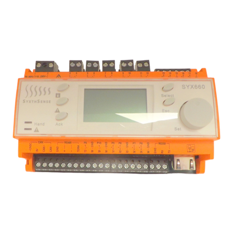
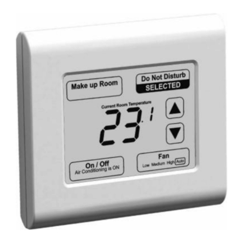
SyxthSense SRC-P-700 Series Instruction manual

Online store: www.syxthsense.com
Enquiries: T: +44 (0)1392 875 414 E: info@syxthsense.com PS CT2.161 V4.13 - 1/34
SRC-P-700 Series Touchscreen
Room Controllers
The SRC-P-700 series controllers have been designed for climate
control in room spaces with modern sharp slim line 3.5" colour
touchscreen interface. The controllers have up to two heating and
cooling temperature control stages, fan speed control, optional
CO2 level and humidity control. The units can be in various climate
control applications fan coil units, chilled ceiling and zone
heating/cooling systems. The SRC-P-700 series controllers have
built-in 7-day schedule and real-time clock.
The controllers are available with wide range of input and output
configurations. The controllers offers PI-control for accurate
energy efficiency.
The devices are available with both Modbus RTU and BACnet
MS/TP communication.
Features
• 24VAC/DC Power Supply
• 3.5" Backlit Touchscreen Display
• BACnet and Modbus Communication Models
• Flush Mounting in the US, UK or EURO Wall Mounting Box
• Built-In Temperature Sensor, up to 2 x Remote NTC10 Sensors
• Wide Range of Input and Output Configurations
• Digital Input for Overrides
• Control of up to four control stages; Boost, Comfort, ECO and
OFF Control Modes
• 7-Day Schedule and Real-Time Clock for Switching Between the
Operating Modes
• Automatic Summer/Winter Time Change-Over
Product sheet CT2.161
Type SRC-P-700
Product Selection Table
123456
1Device type Touchscreen Room Controller, 2RI, 1DI, 3AO (htg/clg/fan), Schedule SRC-P-700
Touchscreen Room Controller, 1RI, 1DI, 2AO (htg/clg), 3RO (fan), 0.5A, Schedule SRC-P-701
Touchscreen Room Controller, 1RI, 1DI, 2AO (htg/clg), 3RO (fan), 7A, Schedule SRC-P-701H
Touchscreen Room Controller, 2RI, 1DI, 1AO (fan), 2DO (htg/clg), Schedule SRC-P-702
Touchscreen Room Controller, 2RI, 1DI, 1AO (EC fan), 3RO (fan), 1RO (htg/clg), Sc
SRC-P-703
Touchscreen Room Controller, 2RI, 1DI, 3RO (fan), 2DO (htg/clg), 7A, Schedule SRC-P-704H
2CommunicaƟon Modbus -MOD
BACnet -BAC
3Power Supply 24 Vac/dc -24
4AddiƟonal measurements No addiƟonal measurement
CO2 -CO2
RelaƟve Humidity -RH
RelaƟve Humidity + CO2 -CO2-RH
6Advanced opƟons No advanced opƟons
0...10 Vdc input(s) (replaces RI input(s)) -AI
5Body color Standard "chrome"
White RAL9010 -W
Black RAL8022 -B
Touchscreen SRC-P-700 Series Room Controllers
Technical Data
Power Supply Power: 24VAC/DC -10%/+15%, 80mA
Display Touchscreen 3.5" Backlit Touchscreen, 320 x 480 pixels, 255K colours
Signal Outputs Analogue Outputs SRC-P-700: 3 x 0..10V < 5mA
SRC-P-701(H): 2 x 0..10V < 5mA
SRC-P-702/703: 1 x 0..10V < 5mA
Relay Outputs SRC-P-701: 3 x 0.5A (res.) at 230VAC
SRC-P-701H/704H: 3 x 7A (res.) / 2.2A (inductive) at 230VAC /
3 x 7A (res.) / 1.3A (inductive) at 115VAC
SRC-P-703: 4 x 0.5A (res.) at 230VAC
Digital Outputs SRC-P-702/704H: 2 x 24VAC 1A Triac (switching to 0V)
Note: Requires 24VAC power supply.
Signal Inputs Built-In Sensor 0..50°C (32..122°F) ±0.5°C (0.9°F) @ 25°C (77°F)

SyxthSense Ltd
Copyright © 2020 SyxthSense Ltd. All rights reserved - 11/2020
PS CT2.161 - 2/34
Online store: www.syxthsense.com
Enquiries: T: +44 (0)1392 875 414 E: info@syxthsense.com
External Sensor Inputs SRC-P-700/702/703/704H: 2 x External NTC10K3 Sensors
(RI1 & RI2)
SRC-P-701: 1 x External NTC10K3 Sensor (RI1)
Note: Resistive Inputs can also act as Volt-Free Digital Inputs
Digital Input 1 x Digital Input, Volt-Free Contact, Impedance <1KOhm
Optional Sensing Characteristics Carbon Dioxide (CO2
Models)
Range 0...5000ppm CO2
Accuracy ± 50ppm + 3% of the reading @ 25°C (@77°F)
Technology Auto Calibrating; Patented Non-Dispersive Infrared (NDIR)
Non-Linearity <1% FS
Warm-Up Time <20 seconds
Response Time 2 minutes
Humidity (RH Models)
Range 0..100%rH
Accuracy ±2% rH (within 20..80% rh)
Communication Modbus (-MOD models)
Protocol Modbus RTU
Interface RS485; maximum 63 devices
Addressing 1..247 via Touchscreen
Communication 9k6/19k2/38k4/57k6/76k8 Baud; Parity None/Even/Odd, 1 or
2 Stop Bits (adjustable through Touchscreen)
BACnet (-BAC models)
Protocol BACnet MS/TP
Interface RS485; maximum 63 devices
MAC Addressing 0.127 via Touchscreen
Device ID Default 651000 + MAC Address, Adjustable
Communication 9k6/19k2/38k4/57k6/76k8 Baud; Parity None/Even/Odd, 1 or
2 Stop Bits (adjustable through Touchscreen)
Connections Terminal Connections
(Power Supply & Analogue
Outputs)
Solid and Stranded Cable
Maximum Size: Solid; 0.05-2.5mm2, Stranded: 0.05-1.50mm2
/ 14 to 30 AWG (UL)
Rising Clamp: Size 2.5 x 2.2mm
Terminal Connections
(Comms and Inputs)
Solid and Stranded Cable; 90° Angle for Wiring
Maximum Size: 0.05 to 1.5mm2 (EN ISO) / 14 to 30 AWG (UL)
Rising Clamp: Size 2.5 x 1.9mm
Environmental Conditions Operating
Temperature 0°C...+50°C (32..122°F)
Humidity 0...95%rh (non-cond.)
Storage
Temperature -30°C...+70°C (-22..158°F)
Humidity 0...95%rh (non-cond.)
Standards CE Conformity CE Directive 2004/108/EC (EMC), 2006/95/EC (LVD)
EN61000-6-3: 2001 (Generic Emission)
EN61000-6-1: 2001 (Generic Immunity)
EN60730-1:2016 (Low Voltage)
EN6100-4-2/4/5/11 (ESD, Transient, Surges, Interruptions)
Degree of Protection IP20
Housing Housing Material Polycarbonate Plastics, Self Extinguishing, Black and Chrome
W-Option: White Enclosure - Black Front
B- Option: Black Enclosure - Black Front
Mounting Wall or Junction Box Mounting
Dimensions W88 x H112 x D43mm; Flush: W88 x H112 x D14.5mm
Weight 220g

SyxthSense Ltd
Copyright © 2020 SyxthSense Ltd. All rights reserved - 11/2020
PS CT2.161 - 3/34
Online store: www.syxthsense.com
Enquiries: T: +44 (0)1392 875 414 E: info@syxthsense.com
SRC-P-700 Wiring
Connections
G0
Y3
G0
485B-
485A+
Din
RI1
RI2 Y2
Y1
24V ~/
G0
WARNING:Switch off the power before any wiring is carried out.
SRC-P-701 Wiring
Connections
G0
RLY1
G0
485B-
485A+
Din
RI1 RLY2
RLY3
24V ~/
RCOM
230V
Y3
Y2
WARNING:Switch off the power before any wiring is carried out.
CONN DESCRIPTION
Y1 0..10Vdc Analogue Output 1 - default fan
speed
Y2 0..10Vdc Analogue Output 2 - default
heating stage 1
Y3 0..10Vdc Analogue Output 3 - default
cooling stage 1
24V 24Vac/dc Supply
G0 0V Common
RI1 Remote NTC10 Temperature Sensor
Input 1 (0-10V with AI option)
RI2 Remote NTC10 Temperature Sensor
Input 2 (0-10V with AI option)
Din Volt-Free Digital Input Contact (dry
contact)
485A+ Modbus / BACnet MS/TP RS485 A+
Connection
485B- Modbus / BACnet MS/TP RS485 B-
Connection
G0 0V Common
CONN DESCRIPTION
RLY1 701: 230V 0.5A Relay - Fan Speed 1
701H: 230V 7A Relay - Fan Speed 1
RLY2 701: 230V 0.5A Relay - Fan Speed 2
701H: 230V 7A Relay - Fan Speed 2
RLY3 701: 230V 0.5A Relay - Fan Speed 2
701H: 230V 7A Relay - Fan Speed 2
RCOM Relay Common
24V 24Vac/dc Supply
G0 0V Common
Y2 0..10Vdc Analogue Output 2 - default
heating stage 1
Y3 0..10Vdc Analogue Output 3 - default
cooling stage 1
RI1 Remote NTC10 Temperature Sensor
Input 1
Din Volt-Free Digital Input Contact (dry
contact)
485A+ Modbus / BACnet MS/TP RS485 A+
Connection
485B- Modbus / BACnet MS/TP RS485 B-
Connection
G0 0V Common

SyxthSense Ltd
Copyright © 2020 SyxthSense Ltd. All rights reserved - 11/2020
PS CT2.161 - 4/34
Online store: www.syxthsense.com
Enquiries: T: +44 (0)1392 875 414 E: info@syxthsense.com
SRC-P-702 Wiring
Connections
G0
G0
485B-
485A+
Din
RI1 Y1
24V ~/
TR2
TR1
RI2
GO
SRC-P-703 Wiring
Connections
G0
RLY1
G0
485B-
485A+
Din
RI1 RLY2
RLY3
24V ~/
RCOM
230V 0.5A
Y3
RI2
RLY4
CONN DESCRIPTION
Y1 0..10Vdc Analogue Output - default fan
speed
TR1 24Vac 1A Triac (switched to 0V)- default
Heating PWM
TR2 24Vac 1A Triac (switched to 0V) - default
Cooling PWM
24V 24Vac/dc Supply
G0 0V Common
RI1 Remote NTC10 Temperature Sensor
Input 1 (0-10V with AI option)
RI2 Remote NTC10 Temperature Sensor
Input 2 (0-10V with AI option)
Din Volt-Free Digital Input Contact (dry
contact)
485A+ Modbus / BACnet MS/TP RS485 A+
Connection
485B- Modbus / BACnet MS/TP RS485 B-
Connection
G0 0V Common
CONN DESCRIPTION
RLY1 230V 0.5A Relay - Fan Speed 1 / On-Off
Valve
RLY2 230V 0.5A Relay - Fan Speed 2
RLY3 230V 0.5A Relay - Fan Speed 3
RCOM Relay Common
RLY4 230V 0.5A Relay - On-Off Valve
24V 24Vac/dc Supply
G0 0V Common
Y3 0..10Vdc Analogue Output 3 - default
cooling stage 1
RI2 Remote NTC10 Temperature Sensor
Input 2 (0-10V with AI option)
RI1 Remote NTC10 Temperature Sensor
Input 1 (0-10V with AI option)
Din Volt-Free Digital Input Contact (dry
contact)
485A+ Modbus / BACnet MS/TP RS485 A+
Connection
485B- Modbus / BACnet MS/TP RS485 B-
Connection
G0 0V Common

SyxthSense Ltd
Copyright © 2020 SyxthSense Ltd. All rights reserved - 11/2020
PS CT2.161 - 5/34
Online store: www.syxthsense.com
Enquiries: T: +44 (0)1392 875 414 E: info@syxthsense.com
SRC-P-704H Wiring
Connections
G0
G0
485B-
485A+
Din
RI1 RLY2
RLY3
24V ~/
RCOM
TR1
RI2
TR2
RLY1
CONN DESCRIPTION
RLY1 230V 7A Relay - Fan Speed 1 / On-Off
Valve
RCOM Relay Common
RLY2 230V 7A Relay - Fan Speed 2
RLY3 230V 7A Relay - Fan Speed 3
TR2 24Vac 1A Triac (switched to 0V) - default
Cooling PWM
24V 24Vac/dc Supply
G0 0V Common
TR1 24Vac 1A Triac (switched to 0V)- default
Heating PWM
RI2 Remote NTC10 Temperature Sensor
Input 2 (0-10V with AI option)
RI1 Remote NTC10 Temperature Sensor
Input 1
Din Volt-Free Digital Input Contact (dry
contact)
485A+ Modbus / BACnet MS/TP RS485 A+
Connection
485B- Modbus / BACnet MS/TP RS485 B-
Connection
G0 0V Common

SyxthSense Ltd
Copyright © 2020 SyxthSense Ltd. All rights reserved - 11/2020
PS CT2.161 - 6/34
Online store: www.syxthsense.com
Enquiries: T: +44 (0)1392 875 414 E: info@syxthsense.com
SRC-P-700 Series User
Interface
The figures below illustrate some of the SRC-P-700 controller user displays. The multi-colour LCD
screen is touch sensitive, easy to adjust and illustrates clearly the plant status information.
HEATING DEMAND
Room
20.1
°C
STATUS INFORMATION
BANNER
INTENSITY OF THE RED ON
THE ENERGY RING
CHANGES DEPENDING ON
DIFFERENCE BETWEEN
EFFECTIVE TARGET AND
ROOM TEMPERATURES, AT
2°C/3.6°F FULL RED
COOLING DEMAND
Target
21.5
°C
PRESS DIM BUTTON TO
SWITCH BACKLIGHT OFF
TARGET SETPOINT
ADJUSTMENT BUTTONS
Outside
10.5
°C
Humidity
45%
Humidity
45%
CO2
700
ppm
TRANSITIONS BETWEEN
ROOM, HUMIDITY, CO2,
OUTSIDE (NETWORK)
FAN STATUS AND
MANUAL CONTROL
(FAN ROTATES
WHEN RUNNING)
Target
21.5
°C
A A
OK CO2 AMBER
ALARM
CO2
700
ppm
CO2 ALARM DISPLAYS
CO2 RED ALARM
CO2
950
ppm
CO2
1300
ppm
SMALL ACTION
CIRCLE
INDICATES
CURRENT MODE -
BUTTON FOR
MODE SCREEN
ACCESS
OFF (AWAY) MODE -
BUTTON TO MODE
SELECTIO SCREEN
Wed 12:43 Wed 12:43
WHEN ENTERING THE MODE
SCREEN THE CURRENT MODE
STATUS IS DISPLAYED.
BY SELECTING THE NEW MODE
THE DEVICE AUTOMATICALLY
RETURNS TO THE HOME
SCREEN (OR AFTER TIMEOUT).
MODE SCREEN
The colour of the ’Energy Ring’ indicates the heating/cooling demand. The ’Energy Ring’ is white at
’deadzone’. The density of red/blue on the ’Energy Ring’ modulates based on how far from the
Effective Heating/Cooling Setpoint the temperature is. When the difference is 2°C/3.6°F the ’Energy
Ring’ is at full density
calcSP
HDz
MEASURED
TEMPERATURE
+- CDz
Deadzone
ENERGY RING COLOURS
HDz - 2°/ 3.6°F CDz + 2° / 3.6°F
.
Touchscreen The SRC controller home screen has a number touch sensitive areas that allow the device settings to
be changed.
• UP and DOWN arrows; to alter the current control target setpoint temperature
• SCREEN DIM ICON; dims the screen backlight/ switches backlight off
• SMALL ACTION CIRCLE (that contains current room and/or floor temperature, CO2, humidity
etc); allows access to FURTHER SETTINGS AND INFORMATION screen; password protected
• FAN SPEED ICON; when FAN display is enabled, the fan ICON can be used to control the fan
speed
• COMFORT/ECO/OFF/BOOST ICON; used to select between COMFORT/ECO/OFF/BOOST
modes. When selected, the MODE SELECTION screen is displayed and can be used to select
the mode.
Programming Times and
Targets
The SRC-700 controllers have up to five programmable time switching times that can be configured to
switch between COMFORT / ECO / OFF / BOOST modes. The times and targets can be set for
individual weekdays or the thermostat can be switched 5+2 mode where the targets are set for
WEEKDAYS or WEEKENDS.
The SCHEDULE OVERVIEW screen shows the current switching targets. By selecting the day it is
possible to adjust the switching times and targets of the device.
NOTE: Switching from the 7 DAYS mode to 5+2 DAYS mode will set all weekday/weekend to the
group settings. When returning back to 7 DAYS mode the setting are required to be re-entered for
each day.

SyxthSense Ltd
Copyright © 2020 SyxthSense Ltd. All rights reserved - 11/2020
PS CT2.161 - 7/34
Online store: www.syxthsense.com
Enquiries: T: +44 (0)1392 875 414 E: info@syxthsense.com
A copy function is available to copy times and target temperatures from one day (or group) to other
day.
SETTING PROGRAM SCHEDULES
7 DAYS OR 5+2 DAYS
MODE SELECTTION
7 Days
7 DAYS PROGRAMMING MODE
SELECT
DAY
Copy
Mon Tue Wed Thu
Fri Sat Sun
Tue
Wed
Thu
Fri
Sat
Sun
Schedule Overview
ECOComfort Off
VISUAL
SCHEDULE
OVERVIEW
06:30 Comfort
13:00 ECO
18:00 Off
Time Target
Edit Schedule
TOUCH TIME TO
CHANGE
SWITCHING
TIME
TOUCH TARGET
TO SELECT
SWITCHING
TARGET
7
4
1
.
0
89
56-
23Esc
EnterDel
7
4
1
0
ENTER SELECTED PERIOD
SWITCHING TIME
:
Monday
Set Switching Time
07:40
01224
18
6
Mon
01224
18
6
Mon
Boost
14:00 Comfort
22:00 Off
EDITING SCHEDULE
Touchscreen Backlight The touchscreen backlight level can be adjusted through the maintenance mode. During the normal
operation after 30 seconds of inactivity, the touchscreen dims to the "stand-by" level set. If the
backlight level is set to 0, the screen backlight switches off.
By pressing the DIM icon when the screen is active the screen is immediately dimmed to the
"stand-by" level. Pressing the DIM icon when the device is in the "stand-by level", switches the
backlight OFF.
The screen backlight is automatically activated when it is touched.
Further Settings and
Information
The FURTHER SETTINGS screen shows additional user settings options on the SRC controllers:-
• LOCK icon is used to lock the thermostat. Number of different lock modes options exist.
• CLEANING icon is used to enable timed (30 seconds) cleaning mode.
• COG WHEEL icon allows entry to the maintenance mode.
• CLOCK icon is used to set the time.
• TIME PROGRAMME ICON is used to set the switching times.
• COG WHEEL icon allows entry to the maintenance mode.
FURTHER SETTINGS AND INFORMATION
LARGE CIRCLE
CONTINUES TO
DISPLAY CURRENT
TARGET - TEMP
DIFFERENCE
USE ESC BUTTON TO
SET OR WAIT FOR A
TIME-OUT OR SELECT
OTHER OPTION
ENTRY SCREEN
TO ENABLE CLEANING MODE
TOUCH THE ICON
SELECT COG WHEEL TO
ENTER MAINTENANCE
MODE (REQUIRES
PASSWORD)
SELECT LOCK ICON TO
LOCK THE DEVICE FROM
TAMPERING
SELECT CLEANING ICON
TO ENABLE CLEANING
MODE. THE DISPLAY
WILL COUNT DOWN
FROM 30 SECONDS
DURING WHICH ALL
BUTTONS ARE DISABLED
ALLOWING SCREEN
CLEANING.
30
Clean Screen
SET TIME
AND DATE
TIME PROGRAMME
ADJUSTMENT
Temperature Control Loop
Operation
The controllers can have up to two heating stages and cooling stages (as default one heating stage
and one cooling stage), and can also carry out automatic change-over from heating to cooling via
digital input / temperature measurement / network.
This allows various control configurations:-

SyxthSense Ltd
Copyright © 2020 SyxthSense Ltd. All rights reserved - 11/2020
PS CT2.161 - 8/34
Online store: www.syxthsense.com
Enquiries: T: +44 (0)1392 875 414 E: info@syxthsense.com
•One/Two Stage Heating Control
•One/Two Stage Cooling Control
• One/Two Stage Heating and One/Two Stage Cooling Control (up to three outputs)
•One Stage Heating/Cooling Control (Change-Over)
The controller modulates the heating and cooling demand outputs according to the calculated setpoint
and the current temperature. The control can be either P-control or PI-control. The calculated setpoint
consists sum of Nominal Setpoint (nSP) and the user setpoint adjustment (SPA).
As default for SRC-700/701, heating stage 1 output is linked to Y2 for modulating 0..10Vdc control,
cooling stage 1 is linked to analogue output Y3. With SRC-702/704H, heating stage 1 is linked to DO1
PWM control and cooling stage 1 is linked to DO2 PWM control.
It is possible to set the control loop outputs to direct/reverse, which reverses the control output (valve)
running direction (valve drives from 100% to 0%). This can be configured individually for each stage in
the Configuration Parameters.
CONTROL OUTPUT
HEATING
STAGE 1
COOLING
STAGE 1
calcSP
SRC600/601/602 - 0..10Vdc
SRC602 - PWM
SRC600/601/602 - 0..10Vdc
SRC602 - PWM
HDz
MEASURED
TEMPERATURE
100%
0% +-
COOLING
STAGE 2
SRC600/601/602 - 0..10Vdc
HEATING
STAGE 2
NOTE: SRC600 has maximum of 3 x 0-10Vdc outputs
NOTE: SRC601 has maximum of 2 x 0-10Vdc outputs
NOTE: SRC602 has maximum of 2 x PWM 24V outputs and 1 x 0-10Vdc outputs.
ECO Deadzone
fSP
2°C /
3.6°F fSP = Frost Setpoint
SRC600/601/602 - 0..10Vdc
HDz = COMFORT Heating Deadzone
CDz
CDz = COMFORT Cooling Deadzone
eHDz eCDz calcSP = Calculated Setpoint
Between heating and cooling stage 1 is a ’deadzone’. With P-control in the ’deadzone’ the cooling and
heating loop demand is 0%. With PI-control, if the temperature remains in the ’deadzone’ for a
prolonged period, the heating/cooling demand ramps to 0%. The ’deadzone’ allows the temperature to
fluctuate around the setpoint without heating or cooling valves starting to open. The SRC has a built-in
lock that prevents cooling and heating demands to be on simultaneously.
The ’deadzone’ has an individual settings (HDz and CDz) for both heating and cooling side allowing
asymmetrical setting. E.g. in some cases it is important that the cooling starts to respond faster than
heating when the temperature deviates away from the setpoint.
Note: Conceptually calcSP - HDz is effective Heating Setpoint and calcSP + CDz is Effective Cooling
Setpoint. For the user it is easier to set and display a single setpoint and the ’deadzone’ limits are set
during the commissioning to provide effective heating and cooling setpoints..
The target temperature is typically adjusted by the user by pressing UP & DOWN buttons. The target
temperature/deadzone is changed in different operating situations as follows;
• COMFORT MODE; target temperature as adjusted by the user (or via the networked system)
and displayed on the screen. The calculated target setpoint (calcSP) consist of the Nominal Set-
point plus the user adjustment (SPA) set via the screen. The user setpoint adjustment is limited
by the Setpoint Adjust Max/Min settings (as default +/-3°).
• ECO MODE; target Nominal Setpoint remains the same.The user adjustment (SPA) is disabled
and the ’deadzone’ settings are expanded to Night Heating Deadzone and Night Cooling Dead-
zone.
• OFF MODE; the device controls to Frost Setpoint (fSP). The user adjustment (SPA) is disabled.
NOTE:If activated, the High/low Limit Control shifts the effective target temperature (calculated
setpoint) as required.
Heating / Cooling
Change-Over
The main temperature control loop heating stage 1 and cooling stage 1 can be forced to operate in
heating or cooling mode using the change-over function. The change-over is carried out using digital
input, temperature measurement or over the network. This allows the same pipe works to be used for
both heating and cooling in different seasons.
The change-over function is activated if it is selected for the DI1/RI1/RI2.
With digital input the change-over is activated when the input is activated. Over the network the
change-over can be activated by setting the change-over parameter on.

SyxthSense Ltd
Copyright © 2020 SyxthSense Ltd. All rights reserved - 11/2020
PS CT2.161 - 9/34
Online store: www.syxthsense.com
Enquiries: T: +44 (0)1392 875 414 E: info@syxthsense.com
High/Low Limit Control
(Reset Control)
If an external NTC10 sensor is fitted (to RI1 or RI2) and
the corresponding high/low limit input has been enabled,
the controller can carry out high limit and/or low limit
control. In high limit control, if the external temperature
exceeds the High Limit setpoint, the main control setpoint
is reduced by the amount set in the Limit Ratio per
degree. E.g. if the Limit Ratio is 2, every degree that the
external temperature exceeds the High Limit setpoint, the
target (setpoint) is reset by 2 degrees.
HIGH/LOW
LIMIT ICON
INDICATES
THAT LIMIT IS
BEING
A
PPLIED
Room
20
.1
°C
Target
21.5
°C
A
Note: RI2 is not available with SRC-701.
The Low Limit control works in reverse. If the external
temperature drops below the Low Limit setpoint, the main
control setpoint is increased by the amount of the ratio for
every degree below the Low Limit setpoint.
The setpoint reset amount follows the formula:-
Setpoint_Reset = (Limit_Setpoint - Temperature ) * Limit_Ratio
NOTE: The target setpoint on the display is not changed during the limitation. The limit icon
indicates active limitation. To see the effective limited setpoint enter Controller Status and
Information display.
Note: The limit function is enabled by setting the Limit Ratio parameter (as default 0.0 =
disabled).
Note: In OFF mode high/low limit function is disabled.
Mode Button and Screen By touching the MODE BUTTON on the HOME
SCREEN, the device enters to the MODE
SCREEN. From the MODE SCREEN the
operating mode of the controller can be
selected.
BOOST MODE
(STATUS &
BUTTON)
RETURN TO HOME
SCREEN
MODE SCREEN
BOOST MODE
BUTTON
COMFORT MODE
BUTTON
ECO MODE
BUTTON
OFF MODE
BUTTON
Room
20
.1
°C
Target
21.5
°C
Wed 12:43
HOME SCREEN
MODE BUTTON AND
MODE INDICATION
BOOST MODE
COMFORT MODE
ECO MODE
OFF MODE
The possible selections for the MODE screen
are:-
•BOOST MODE
• COMFORT MODE
•ECO MODE
•OFF MODE
After selecting the Mode the device
automatically returns to the HOME SCREEN. If
no buttons are pressed the device returns
automatically after a timeout. Alternatively the
return button can be pressed to return.
The Mode button has the following
configuration options:-
• Mode Indication Only
• Active Access to Mode Screen (default)
MODE SCREEN is protected by STAFF
ACCESS code. As default the STAFF CODE is
set as ’0000’ and no password is required to
enter MODE screen (from Fw4.13 onwards).

SyxthSense Ltd
Copyright © 2020 SyxthSense Ltd. All rights reserved - 11/2020
PS CT2.161 - 10/34
Online store: www.syxthsense.com
Enquiries: T: +44 (0)1392 875 414 E: info@syxthsense.com
ECO Mode The device can be switched to ECO mode via network, via
digital input (e.g. PIR) or via the touchscreen.
ECO MODE
INDICATION
Room
20.1
°C
Target
21
.5
°C
AUTO
In the ECO mode the controller starts to control to ECO
Heating/Cooling Deadzone and the user setpoint
adjustment (SPA) is removed.
In the ECO mode the CO2 and Humidity loops are
switched to 0%.
The ECO mode can be selected/and cancelled using the
MODE BUTTON (if enabled), The ECO mode is also
indicated by the not showing the setpoint adjustment
buttons.
CONTROL OUTPUT
calcSP
(Default 4.0°C/9.2°F)
HDz
MEASURED
TEMPERATURE
100%
0% +-
eHDz
CDz
eCDz
ECO Deadzone
HEATING STAGE 1
COOLING STAGE 1
HEATING STAGE 2
COOLING STAGE 2
ECO MODE TEMPERATURE CONTROL
calcSP= Calculated Setpoint (Default 21°C/70°F)
eHDz = ECO Mode Heating Deadzone
eCDz = ECO Mode Cooling Deadzone
SRC600/601/602 - 0..10Vdc
SRC602 - PWM
SRC600/601/602 - 0..10Vdc
SRC602 - PWM
Note: If the 7 Day Schedule has been activated, the device starts to use the operating mode set at the
next switching point (e.g. if the next switching point is COMFORT MODE, the devices returns to
COMFORT mode).
OFF Mode The controller can be switched to OFF mode via digital
volt-free input (e.g. PIR), via the MODE BUTTON or
via the communication network (system configuration).
Room
22
.7
°C
Target
8.0
°C
A
OFF MODE
INDICATION
DIMMED
SCREEN AND
OFF SETPOINT
DISPLAY
In the OFF mode all temperature/CO2/humidity control
outputs are switched off to 0% level.
When in OFF mode if the temperature drops below the
OFF FROST Setpoint, the frost protection is activated,
the SNOWFLAKE icon is displayed on the screen and
the heating stages are switched to 100% and the fan
speed output is switched to 33%. When the
temperature exceeds the OFF FROST setpoint plus 2
degrees, the frost condition is deactivated.
CONTROL OUTPUT
nSP
nSP= Nominal Setpoint (Default 21°C / 70°F)
MEASURED
TEMPERATURE
100%
0% +-
fSP
2°C /
3.6°F fSP = Frost Setpoint (Default 8°C / 46°F)
OFF MODE TEMPERATURE CONTROL
Note: In frost condition the
Fan Demand is set @ 33%.
Note: If the 7 Day Schedule has been activated, the device starts to use the operating mode set at the
next switching point (e.g. if the next switching point is COMFORT MODE, the devices returns to
COMFORT mode).

SyxthSense Ltd
Copyright © 2020 SyxthSense Ltd. All rights reserved - 11/2020
PS CT2.161 - 11/34
Online store: www.syxthsense.com
Enquiries: T: +44 (0)1392 875 414 E: info@syxthsense.com
Boost Mode Boost mode can be activated through the MODE
button.The Boost mode can be used e.g. to boost the
temperature in the morning, or increase ventilation on
high CO2 measurement.
BOOST MODE
INDICATED BY
THE BOOST
BUTTON
Target
25
.0
°C
AUTO
BOOST
TARGET
TEMPERATURE
(IF TEMP
BOOST)
Room
20.1
°C
The boost mode has Boost Target parameter that
selects the target setpoint that the boost mode applies
to. The target options are:-
• Temperature Setpoint (default)
• CO2 Setpoint
• Humidity Setpoint
• Dehumidity Setpoint
• Fan Demand
• Aux Setpoint
In addition the Boost Mode has boost target setpoint
(as default 25.0). When the Boost mode is activated the selected setpoint is changed to the Boost
Target. E.g in case of temperature heating boost, the target setpoint is increased. In case of CO2
boost the CO2 target setpoint is reduced.
Boost Mode has also built in timer. By setting the Boost Time to 1 to 480 minutes, this is the maximum
Boost time. By setting the Boost Time to ’Permanent’ there is no maximum Boost Time.
The boost mode continues to run until Maximum Boost Time has been reached, or if the
Measurement reaches the Boost Target.
NOTE: The target for the temperature boost can be above or below the current setpoint. The fan
boost target level is selectable between 1-100%.
The Boost Mode is also cancelled when the time reaches the next switching point on the 7-Day
schedule point regardless of the Boost Time or Current Measurement. Please note that at the next
switching time the target (COMFORT/ECO/OFF/BOOST) must be different from the target in the
current period in order to time to count as switching point.
NOTE: Digital Input can also be configured to activate the Boost.
Fan Speed Control Fan speed control logic adjusts the fan speed based on the demand from 0% to 100%. The fan speed
can be configured to follow different control loop outputs using the Fan Speed Source configuration
parameter. The options are:-
• HEATING 1 AND COOLING 1 STAGE (Default)
• HEATING STAGE 1
• COOLING STAGE 1
• HEATING AND COOLING STAGE 2
• HEATING STAGE 2
• COOLING STAGE 2
• CO2 LOOP
• HUMIDITY LOOP
• DE-HUMIDITY LOOP
• MAXIMUM VAV; Maximum of Cooling Stage 1 and CO2 Loops
• MAX TEMP/HUM; Maximum of Heating Stage 1, Cooling Stage 1 and Humidity Loops
As default the fan speed control is configured to follow the Heating and Cooling Stage 1. This means
that e.g. if Heating Stage 1 output is 55%, and the minimum fan level is set to 0%, the fan speed loop
output is also 55%.
Minimum Fan Level parameter is used to set the minimum fan speed during the operation in
COMFORT mode. The fan demand is scaled between the Minimum Fan Level and Maximum (100%)
- see diagram below for example. The fan speed is 0% in the deadzone area unless Fan Off Delay is
set to 0 = Indifinite (default - the fan remains at Minimum Fan Level in deadzone area).
CONTROL OUTPUT
calcSP
Cooling Stage 1 Level
MEASURED
TEMPERATURE
100%
0% +-
Dz
calcSP = Calculated Setpoint
Dz = Comfort Deadzone
Min. Fan Level = 20%
Fan Speed Source = Htg/Clg Stage 1
EC FAN CONTROL EXAMPLE
Heating Stage 1 Level
20%
40%
Min. Fan Level = 40%
Fan Speed, Min Level = 40%
Fan Speed, Min Level = 20%

SyxthSense Ltd
Copyright © 2020 SyxthSense Ltd. All rights reserved - 11/2020
PS CT2.161 - 12/34
Online store: www.syxthsense.com
Enquiries: T: +44 (0)1392 875 414 E: info@syxthsense.com
The Fan Off Delay defines time how long the fan overruns in the deadzone (after no demand). E.g. by
setting the Fan Off Delay to 30 seconds, the fan switches off after the Htg/Clg Stage 1 demand has
remained within the deadzone for 30 seconds (example above).
If maximum speed is required to be set for the fan, this is confugured by setting the maximum level in
the analogue output (Y1, Y2, Y3) scaling. As default fan speed is configured for Y1.
In ECO mode the Fan Speed control follows the same principle as in the COMFORT mode. In OFF
mode the fan is Off unless frost has been detected in which case the fan output is set to 33%.
Automatic Fan Speed Display
Fan speed can be displayed on the
screen using coloured bar indicating
the speed and rotating fan icon. The
display is enabled through the Fan
Speed Display parameter.
Room
20.1
°C
FAN SPEED INDICATION AND
CONTROL, AUTO IS DISPLAYED
WHEN UNDER AUTOMATIC
CONTROL. WHEN RUNNING
Target
21.5
°C
FAN SPEED INDICATION IN
AUTOMATIC CONTROL
0% to 8%
A
A
A
A
A
A
A
A
8% to 25%
25% to 41%
41% to 58%
58% to 74%
74% to 92%
92% to 100%
Options are:-
• NONE; no display (Default)
• NO INPUT; no user adjustment
• 0-1; Off/On
• 0-1-2; 2-Speed
• 0-1-2-3; 3-Speed
• 0-1-2-3-4-5-6; 6-Speed
When in Automatic control ’A’ is
displayed above the coloured bar. The
number of bars displayed depends on
the fan speed - switching levels described above.
Manual Fan Speed Override
The Fan Speed Display parameter
is used to configure Manual Fan
Speed Override options; On/Off,
2-Speed, 3-Speed or 6-Speed.
ON/OFF MANUAL
FAN OVERRIDE
3-SPEED MANUAL
FAN OVERRIDE
2-SPEED MANUAL
FAN OVERRIDE
M
AFTER FULL SPEED AUTO
OPTION IS AVAILABLE TO
RETURN BACK TO AUTO-
MATIC CONTROL
6-SPEED MANUAL FAN
CONTROL
M
17%
33%
0%
50%
67%
83%
100%
A
Auto
SPEED SET BY
CONTROLLER
100%
0%
50%
100%
0%
33%
67%
0%
100%
M
M
M
M
M
M
M
M
M
M
M
M
A
Auto
SPEED SET BY
CONTROLLER
A
Auto
SPEED SET BY
CONTROLLER
A
Auto
SPEED SET BY
CONTROLLER
Once activated the user can
override the Fan Speed by
touching the Fan Icon on the
screen. The desired speed can be
set by touching multiple times on
the screen. When Manual override
is active ’M’ is displayed above the
coloured speed bar.
In ECO mode Manual Override is
active. In OFF mode manual
override is disabled.
NOTE: Manual Fan Override sets
the Fan Speed to defined values as described above and the Min. Fan Level parameter is
ignored.
Auxiliary Heating Control
Loop
The SRC-700 series controllers have an auxiliary heating temperature control loop. The auxiliary
control loop provides additional PI-control function for applications where second control loop is
required e.g. second zone temperature control for bathrooms. The auxiliary control loop is activated
by selecting Aux control for RI1 or RI2 input.
Note: RI2 is not available with SRC-701.
CO2 Sensor Control Loop
Operation (SRC-70x-CO2
Models)
The CO2 models can measure and control
the CO2 level. This can then be used in
demand based control applications. The
CO2 control output can then be configured
to linked to any of the physical control
outputs Y1, Y2 or Y3, or used in maximum
demand control (MAX VAV, MAX FAN
options)
CONTROL
OUTPUT
CO2 Control
SP= Setpoint e.g. 800ppm
PB = Proportional Band
100%
PB
e.g 400ppm
SP
0%
CO2 Level
-+
0 ppm
2000 ppm
LOOP OUTPUT
The CO2 control loop output corresponds
to the CO2 setpoint and the CO2
proportional band. If configured as Direct
Control (typical), then if the CO2 level
increases above the setpoint the loop output starts to modulate to 100%. When the CO2 level is the
amount of the Proportional Band above the setpoint, the loop output is 100%. The configuration is
done via the configuration parameters. The CO2 control loop can also be configured to operate as

SyxthSense Ltd
Copyright © 2020 SyxthSense Ltd. All rights reserved - 11/2020
PS CT2.161 - 13/34
Online store: www.syxthsense.com
Enquiries: T: +44 (0)1392 875 414 E: info@syxthsense.com
Proportional + Integral control by changing the Integral Action Time from 0 to a required value. The
actuator direction can be changed via Output Direction parameter (Direct, Reverse).
In the OFF mode the CO2 loop output is set to 0%. In the ECO mode the CO2 loop operates as in the
day mode.
VAV Maximum Demand
Each of the analogue outputs can also be configured as "Maximum VAV Demand". In this case the
corresponding output (Y1, Y2, Y3) takes the maximum of the CO2 Loop and Cooling Temperature
Loop demand output. This is typically used in demand based ventilation (VAV) to control fresh air
damper when there is either demand for more fresh air, or demand for temperature cooling (typically
fresh air cools down the room space).
Maximum Fan Demand
Each of the analogue outputs can be configured ad "Maximum Fan Demand". In this configuration the
corresponding output (Y1, Y2, Y3) takes the maximum demand of the CO2 Control Loop and Fan
Speed Control Loop. This can provide fan speed boost at high CO2 level and when the fan speed
temperature loop has increased the demand.
Humidity Control Loop
Operation (-RH option)
The RH models can measure and control
the relative humidity level. This can then be
used in demand based control applications
to increase the fresh air supply e.g. in the
high humidity conditions. The control loop
has both de-humidification and
humidification outputs that can be linked to
any of the physical control outputs Y1, Y2,
or Y3. The direction of the both outputs can
also be reversed to driver the actuators
100-
CONTROL
OUTPUT
De-humidification
SP= Setpoint e.g. 50%rH
100%
Proportional Band
e.g 5%rH
SP
0%
Humidity %rH
-+
0%rH
100%rH
LOOP OUTPUT
Humidification
0% instead of 0-100%.
Cleaning Mode After entering FURTHER INFORMATION screen, by selecting the CLEANING icon, it is possible to
activate the cleaning mode. The SRC will enter a "Clean Screen" state where all touchscreen presses
are ignored and 30 second countdown timer is displayed. This allows cleaning of the device itself.
Lock Mode After entering FURTHER INFORMATION screen, by selecting the
LOCK icon it is
0000
89
56-
23Esc
OKDel
Lock Code
Enter Code
7
4
1
0
possible to lock the device. Now by entering the
LOCK CODE, the device lock state can be activated.
The lock mode can be configured to work in different ways as
described at the below table.
• DISABLED: Lock Mode Icon Not Available
• ON/OFF ONLY: Allows Mode Buttons Only
• ADJUST ONLY: Allows Temperature Adjustment Only
• NO INPUT: All Buttons Locked
If the lock code is set to 0000 (default), there is no need to enter the
lock code and the lock entry screen is bypassed.
Remote Sensor RI1 and RI2
Inputs
A remote NTC10k3 sensor can be connected to the RI1 and RI2 inputs to be used for different control
and display purposes. The options are:-
• DISABLED; the measurement is disabled
• ROOM; the input is used for the main temperature control loop
• FLOOR; the input is used for High/Low Limit Control
• OUTSIDE: the input is used to show the Outside Temperature
• NETWORK NTC10; the resistive input is available over the communication network as tempera-
ture.
• NETWORK 0-10V; the input is used as 0.10V network monitoring input (requires AI option)
Lock Mode Options Icon Active / Visible
Lock Up and Down OFF Fan Speed /
Schedule /
Time
Mode Buttons
DISABLED NO YES YES YES YES
ON/OFF ONLY YES NO YES NO YES
ADJUST ONLY YES YES NO NO NO
NO INPUT YES NO NO NO NO

SyxthSense Ltd
Copyright © 2020 SyxthSense Ltd. All rights reserved - 11/2020
PS CT2.161 - 14/34
Online store: www.syxthsense.com
Enquiries: T: +44 (0)1392 875 414 E: info@syxthsense.com
• CO2; the input is used as CO2 0..10Vdc measurement for CO2 control (requires AI option)
• MAIN LOOP; the 0..10Vdc voltage is used for the main temperature control (requires AI option)
• CLOSE FOR ECO; the input operates as volt-free input to override to ECO mode when closed
• OPEN FOR ECO; the input operates as volt-free input to override to ECO mode when open
• CLOSE FOR OFF; the input operates as volt-free input to override to OFF mode when closed
• OPEN FOR OFF; the input operates as volt-free input to override to OFF mode when open
ROOM allows remote temperature sensor to be used for the main temperature loop control. The
internal temperature sensor is disengaged from control.
FLOOR option links the temperature measurement to the High/Low Limit control. When the Floor
Control is selected for RI1/RI2, the touchscreen SMALL ACTION CIRCLE starts to display the Floor
Temperature (configurable). Note if both RI1/RI2 set to Floor Control RI1 takes precedence.
OUTSIDE allows outside (or network) temperature to be displayed on the screen. When the Outside is
selected for RI1/RI2, the touchscreen SMALL ACTION CIRCLE starts to display the Outside
Temperature (configurable). Note if both RI1/RI2 set to Outside RI1 takes precedence
NETWORK NTC10 option makes the NCT10 measurement available as temperature over the
network.
Digital Input Modes
"CLOSE FOR" Configuration - The resistive input can be used as digital volt-free contact can be linked
to e.g. external timer to switch the device to OFF mode during the timed period. When the device sees
transition from open (COMFORT) to close (ECO/OFF MODE), the operating mode does not change
until the Delay Timer has expired.
"OPEN FOR" Configuration - The resistive input can be used as digital volt-free input to activate ECO
or OFF mode when the contact opens. In this mode it can be connected to a window switch, door card
switch or PIR sensor. When the device sees transition from closed to open, the operating mode does
not change until the countdown timer has expired (DIGITAL INPUT DELAY setting).
Note: Resistive Inputs as a Digital Input operate with approx. ten seconds delay and are not
instantaneous. Therefore they are not suitable for fast switching (transition will be missed
during the inherent delay time).
Note: RI2 is not available with SRC-701.
2 x 0..10Vdc Input (AI
Options
If the SRC unit has been ordered with AI option, then inputs RI1 and RI2 become 0..10Vdc inputs.
NETWORK 0-10V; this selection allows the 0..10Vdc measurement to be converted to 0..100% and
the measurement can be monitored over the network.
CO2; this selection converts the 0..10Vdc input to 0..2,000ppm. The measurement is available over
the network for monitoring, and the measurement is automatically linked to the CO2 control.
MAIN LOOP; this selection converts the 0..10Vdc input to 0..50°C. The measurement is available over
the network for monitoring, and the measurement is automatically linked to the main temperature
control loop.
Note: RI2(AI2) is not available with SRC-701.
DI Digital Input The digital volt-free contact can be configured to the following options are:-
• CLOSE FOR ECO; Default
• OPEN FOR ECO
•CLOSE FOR OFF
• OPEN FOR OFF
• CHANGEOVER; changes stage 1 control between heating and cooling
• DISABLE COOLING; disabling the cooling stages when ON (condensation)
• CONTACT ALARM
•NETWORK
• CLOSE FOR BOOST (with CE-option only)
• OPEN FOR BOOST (with CE-option only)
"OPEN FOR" Configuration - The digital volt-free input can be used to activate ECO or OFF mode
when the contact opens. In this mode it can be connected to a window switch, door card switch or PIR
sensor. When the device sees transition from closed to open, the operating mode does not change
until the countdown timer has expired (DIGITAL INPUT DELAY setting).
"CLOSE FOR" Configuration - The digital volt-free contact can be linked to e.g. external timer to
switch the device to OFF mode during the timed period. When the device sees transition from open
(COMFORT) to close (ECO/OFF MODE), the operating mode does not change until the Delay Timer
has expired.
CHANGE-OVER - The digital input can also be used to override from heating to cooling mode. The
device works in the heating mode when the contact is open, and in the cooling mode when the contact
is closed.

SyxthSense Ltd
Copyright © 2020 SyxthSense Ltd. All rights reserved - 11/2020
PS CT2.161 - 15/34
Online store: www.syxthsense.com
Enquiries: T: +44 (0)1392 875 414 E: info@syxthsense.com
CONDENSATION - when the digital input is closed the cooling loops are set to 0% to prevent
condensation happening. In this mode digital input is typically connected to a condensation sensor.
CONTACT ALARM - when the contact closes the "DI Contact Alarm" alarm message is displayed on
the screen.
NETWORK; the digital input is used for network monitoring purposes.
CLOSE/OPEN FOR BOOST - when digital input activates the controller operates in Boost mode, until
the digital input de-activates (only with CE-option). With the digital input boost the ’Target’ text is
replaced by ’Boost’ text.
Note: Digital Input Delay Timer parameter applies to all settings.
Analogue Outputs The controller has three analogue 0-10Vdc outputs that are typically linked to the control loop outputs.
The following list states the possible options:
• NETWORK; As a network 0-10Vdc output variable
• HEATING STAGE 1; 0-10Vdc output is linked to Heating Stage 1
• HEATING STAGE 2; 0-10Vdc output is linked to Heating Stage 2
• COOLING STAGE 1; 0-10Vdc output is linked to Cooling Stage 1
• COOLING STAGE 2; 0-10Vdc output is linked to Cooling Stage 2
• EC FAN; 0-10Vdc output is linked to Fan Control Loop Output
• CO2; 0-10Vdc output is linked to CO2 Control Loop Output (CO2 Models)
• MAXIMUM VAV; 0-10Vdc linked to maximum of the Cooling stage 1 and CO2 loops
• MAXIMUM FAN; 0-10Vdc linked to maximum of the CO2 loop and fan loop
• HUMIDIFICATION; 0-10Vdc output is linked to Humidity Control Loop Output (RH Models)
• DE-HUMIDIFICATION; 0-10Vdc output is linked to De-Humidity Control Loop Output (RH Mod-
els)
• AMBER/RED; 0-10dc is @ 50% when Amber or Red alarm is active
• RED; 0-10Vdc is @ 100% when Red alarm is active
• HEATING STAGE 1 STAT; see RELAY OUTPUT / ON-OFF control chapter
• COOLING STAGE 1 STAT; see RELAY OUTPUT / ON-OFF control chapter
• FAN STAT; see RELAY OUTPUT / ON-OFF control chapter
• AUX LOOP; see AUXILIARY HEATING CONTROL LOOP chapter
• 6-PORT; see 6-PORT VALVE control chapter
• 6-PORT REVERSE; see 6-PORT VALVE control chapter (reverse operation)
Analogue Output Scaling /
Output Limitation
Each of the analogue outputs (Y1,Y2,Y3) can have
• Output minimum voltage (percentage)
• Output maximum voltage (percentage)
The connected control loop output 0..100%is then scaled from minimum voltage to maximum voltage.
For example in the EC fan control, if the fan is required to run always at minimum level, the minimum
control output voltage can set to 10% (1V) and the maximum output 70% (7V). In this case the control
loop output 0..100% is scaled to be 10..70% at the analogue output. This allows maximum noise
levels to be limited and the fan to have a minimum fan speed.
The values are available via the communication network from network master read/write.
Relay Outputs / Fan Speed
Control
(SRC-701/SRC-703/SRC-704
H)
SRC-701(H), SRC-703 and SRC-704H have 3 relay outputs that be used to control 3-speed fans. The
relay 1 is switched ON approx. 30% of fan demand, relay 2 is switched ON at approx. 60% of fan
demand and relay 3 is switched ON approx 90% of fan demand. Only one relay is on at any given
time. The relays are switched OFF approx 20% below the fan switch ON level.
NOTE:For the fan relay outputs to operate, the Y1 (Analogue Output Y1 Mode) has be set to
’Modulating Fan’ (default setting).
NOTE:SRC-701H/704H relays are rated 7A resistive. SRC-701/703 relays are rated 0.5A
resistive.
Relay Output / On-Off
Control (SRC-703)
SRC-703 have 4th 230Vac relay that can be used to switch 230Vac On/Off. The output can be used to
switch heating valves, cooling valves or plant enable outputs.This is done by configuring the output Y2
setting to one of the dollowing settings:-
HEATING STAGE 1 STAT; thermostatic switching of output, 100% (SRT-703 RLY4 via Y2 ON) when
Heating1 Stage at 10% or over, switches back to 0% (SRT-703 RLY4 via Y2 OFF) when Heating1
Stage output 0%
COOLING STAGE 1 STAT; thermostatic switching of output, 100% (SRT-703 RLY4 via Y2 ON) when
Cooling1 Stage at 10% or over, switches back to 0% (SRT-703 RLY4 via Y2 OFF) when Cooling1
Stage output 0%
FAN STAT; thermostatic switching of output, 100% (SRT-703 RLY4 via Y2 ON) when Fan Loop at
10% or over, switches back to 0% (SRT-703 RLY4 via Y2 OFF) when Fan Loop output 0%
As default for SRC-703 the Y2 has been configured as ’HEATING STAGE1 STAT’.

SyxthSense Ltd
Copyright © 2020 SyxthSense Ltd. All rights reserved - 11/2020
PS CT2.161 - 16/34
Online store: www.syxthsense.com
Enquiries: T: +44 (0)1392 875 414 E: info@syxthsense.com
NOTE: With SRC-703 you can also configure Y1 to ’HEATING1 or COOLING1 STAT’. With this
configuration RELAY3 becomes also as ON/OFF valve output. Therefore the SC-703 controller
can control both heating and cooling ON/OFF valves (and EC Fan via 0-10Vdc output).
PWM Control / Digital
Outputs
(SRC-702/SRC-704H)
The SRC-702/SRC-704H controller has two digital triac outputs. The digital outputs are used for PWM
control for heating and cooling valves. The PWM period is set in the INPUTS/OUTPUTS PWM Period
Setting. The below diagram illustrates the principle of the PWM control..
HEATING
STAGE1
OUTPUT
HEATING
STAGE 1
calcSP
HDz
°C / °F
100%
0% +-
PWM CONTROL EXAMPLE (HEATING STAGE1 - DO1)
HDz = COMFORT Heating Deadzone
CDz
calcSP = Calculated Setpoint
230 Vac L
Transformer
230 Vac N
Fuse
24Vac
0Vac
Clg Actuator
Thermic
(PWM)
Absolute
Max. 27.6VAC
G0
G0
485B-
485A+
Din
RI1 Y1
24V ~/
DO2
DO1
RI2
SRC-602
GO
Htg Actuator
Thermic (PWM)
60% Example:
Htg1 = 60%
PWM Output
60% of time: ON = 0.6 * 30 = 18s
40% of time: OFF = 0.4 * 30 = 12s
DIGITAL PWM OUTPUT (DO1)
OFF
ON
TIME (seconds)
PWM Period Setting: 30s (Default)
18s 12s
NOTE:With SRC-703/704H analogue outputs Y2 & Y3 are not available. Y1 is available for EC
Fan control (or other valid output control - see Y1 options). With SRC-704H the Y1 is set as
default ’Modulating Fan’, and the device does not have 0-10Vdc outputs.
NOTE:Please note that DO1 and DO2 are 24Vac Triacs switching to 0V. Please follow the above
wiring diagram.
Belimo 6-Port Control Mode The SRC-700 controller can be configured to control Belimo 6-Port valve by selecting 6-Port or 6-Port
Reverse mode for the analogue output (Y1/Y2/Y3). The diagram below illustrates the operation.
Note: Analogue Output Scaling/Anti-JAM is not available in the 6-Port and 6-Port Reverse
modes. Number of Heating and Cooling Stages must be set at minimum to one.
AntiJAM Valve Exercise
Function
If the AntiJAM function is enabled the controller monitors for inactivity. If the control outputs have been
fully closed or fully open more than the AntiJAM period, the controller will open/close the outputs to by
30% for a short period of time. The AntiJAM function is enabled through the configuration parameters
by selecting the required AntiJAM period by days.
Alarm Display The SRC-700 controller provides two
Alarm Modules each of which can be
configured to detect and display alarm
condition on either CO2, Humidity or
Temperature Sensor (internal or external
depending on which is being used). The
alarm function can be disabled by setting
the alarm source as “NONE”. Alarms are
disabled by default.
CO2 AMBER ALARM CO2 RED ALARM
Target
21.5
°C
Target
21.5
°C
AA
CO2
950
ppm
CO2
1300
ppm
Each Alarm has three alarm states – No
Alarm, Amber and Red. When in alarm
the alarm is displayed by alarm bell in
ACTION CIRCLE. The ACTION CIRCLE
rotates all active measurements so the
alarm is displayed when the
corresponding measurement is
displayed.
HIGH LIMIT ALARM
DEMAND
nSP
HDz/CDz = Comfort Zero Energy
Deadzone (Default 0.5°C)
nSP= Nominal Setpoint (Default 21°C)
HDz
MEASURED
TEMPERATURE
100%
0%
+- CDz
Zero Energy
Deadzone
HEATING STAGE 1
COOLING STAGE 1
2V
7V5V
10V
SEQUENCE 1 SEQUENCE 2
MAX
FLOW
MIN
FLOW 6-WAY VALVE CONTROL
SIGNAL (Y1/Y2/Y3)
6-WAY; HTG1 = 5V to 2V, CLG1 = 7V to 10V
6-WAY REVERSE; HTG1 = 7V to 10V,
CLG1 = 5V to 2V
ANALOGUE OUTPUT MODES

SyxthSense Ltd
Copyright © 2020 SyxthSense Ltd. All rights reserved - 11/2020
PS CT2.161 - 17/34
Online store: www.syxthsense.com
Enquiries: T: +44 (0)1392 875 414 E: info@syxthsense.com
If the Red threshold is set higher than the amber threshold:
If Sensor >=Amber Threshold; Alarm = Amber
If Sensor >= Red Threshold; Alarm = Red
Hysteresis acts to prevent a return to a lower alarm level until the Sensor value falls to a Threshold -
Hysteresis
LOW LIMIT ALARM
If the Amber threshold is set higher than the Red Threshold then:
If Sensor <= Amber Threshold; = Amber
If Sensor <= Red Threshold; Alarm = Red
Hysteresis acts to prevent a return to a lower alarm level until the Sensor value rises to a Threshold +
Hysteresis.
Sensor Fault Display When entering FURTHER
INFORMATION AND SETTINGS
screen and a sensor/input fault is
active, select the fault icon for more
information.
FURTHER SETTINGS AND
INFORMATION
SELECT FAULT ICON FOR MORE
INFORMATION
Notifications
Internal Sensor Failure
Remote Sensor 1 Fault
Digital Contact Fault
Remote Sensor 2 Fault
The typical alarm reasons are:
• External sensor 1 (Res1) fault
(when activated; out of range)
• External sensor 2 (Res1) fault
(when activated; out of range)
• Built-in sensor fault
• Digital Input Alarm
Controller Status
Information Display
After entering CONFIGURATION
PARAMETER GROUP screen and
selecting the INFO icon it is possible
to see the current status information
of the controller. The page shows the
current measurement and output
information.
LIVE INFORMATION
SCREEN
SELECT INFO ICON FOR
CONTROLLER STATUS
Status Information
Built-In Sensor 24.8
RI_1 12.8
RI_2 --.-
DI_1 On
CO2 1200
Humidity 51.7
Target 21.7
Heating Demand 78
Cooling Demand 0
Fan Demand 78
CO2 Demand 65
Humidity Demand 12
AO1 78
AO2 65
AO3 12
De-Hum Demand 0
Operating Modes
Parameter Groups
Display
Control Settings
Measurements
Network
Configuration Parameters
Nominal Setpoint
21.0
Control Settings
Fan, Boost
Parameter Groups
Alarms
Control Settings
Inputs & Outputs
System
Heating DZ COMFROT
0.5
Cooling DZ COMFORT
0.5
Heating DZ ECO
4.0
ENTER MAINTENANCE CODE FOR
MAINTENANCE MODE
CLICK TO ACCESS SETTINGS
GROUP
CLICK TO CHANGE
SETTING
ACCESS
MORE
SETTINGS
6666
89
56-
23Esc
OKDel
Maintenance Code
Enter Code
7
4
1
0

SyxthSense Ltd
Copyright © 2020 SyxthSense Ltd. All rights reserved - 11/2020
PS CT2.161 - 18/34
Online store: www.syxthsense.com
Enquiries: T: +44 (0)1392 875 414 E: info@syxthsense.com
The SRC devices are configured to operate in different modes via the configuration parameters
accessible through the maintenance mode.
To enter the maintenance mode click the COG WHEEL icon in the FURTHER SETTINGS SCREEN
and enter the maintenance mode password (default 6666).
NOTE:The maintenance mode password can be changed in the configuration settings. Make
sure that you note the new password if changed. If the Maintenance Code is set as 0000, the
Maintenance Code entry screen is bypassed (i.e. no protection).
NOTE:It is good practice to reset the device after the configuration has been completed. Soft
reset is automatically carried out after entering and exiting System configuration menu, or
alternative power cycle the device.
CONTROL SETTINGS
Parameter Name Description Range
Nominal SP Nominal Setpoint (Temperature Control) 0.0...95.0°C/°F (Default 21.0°C)
Heating DZ COMFORT Heating Deadzone in COMFORT mode 0.0...25.0°C/°F (Default 0.5°C)
Cooling DZ COMFORT Cooling Deadzone in COMFORT mode 0.0...25.0°C/°F (Default 0.5°C)
Heating DZ ECO Heating Deadzone in ECO Mode 0.0...25.0°C/°F (Default 4.0°C)
Cooling DZ ECO Cooling Deadzone in ECO Mode 0.0...25.0°C/°F (Default 4.0°C)
Frost SP Night Frost Setpoint (OFF Mode) 0.0...95.0°C/°F (Default 8.0°C)
Setpoint Adj. Max. Temperature Setpoint Maximum Adjustment 0.0...20°C/°F (Default 3.0)
Setpoint Adj. Min. Temperature Setpoint Minimum Adjustment -20.0...0°C/°F (Default -3.0)
PB Temperature Control Proportional Ban 1.0..50.0 °C/°F (Default 4.0)
IA Integral Action time of the temperature control loop.
Set to 0 to disable.
0..1,200 seconds (Default 600s)
Heating Stages Number of Heating Stages 0 = None
1 = 1-Stage (Default)
2 = 2-Stages
Heating Stage 1 Dir. Heating Stage 1 Direction 0 = Reverse (Default)
1 = Direct
Heating Stage 2 Dir. Heating Stage 2 Direction 0 = Reverse (Default)
1 = Direct
Cooling Stages Number of Cooling Stages 0 = None
1 = 1-Stage (Default)
2 = 2-Stages
Cooling Stage 1 Dir. Cooling Stage 1 Direction 0 = Reverse
1 = Direct (Default)
Cooling Stage 2 Dir. Cooling Stage 2 Direction 0 = Reverse
1 = Direct (Default)
Aux. SP Auxiliary Heating Control Loop Setpoint 0.0...95.0°C/°F (Default 21.0°C)
Aux. PB Auxiliary Heating Control Loop Proportional Band 1.0..50.0 °C/°F (Default 4.0)
Aux. IA Auxiliary Heating Control Loop Integral Action 0..1,200 seconds (Default 600s)
Aux Dir. Auxiliary Control Loop Actuator Direction (actuator
direction, Direct = 0..100%, Reverse = 100..0%)
0 = Reverse Acting
1 = Direct Default)
CO2 SP CO2 Setpoint 0..5000ppm (Default 1,000 ppm)
CO2 PB CO2 Proportional Band 10..5000 ppm (Default = 300 ppm)
CO2 IA Integral Action time of the CO2 control loop. Set to 0
to disable.
0..10,000 seconds (Default 0)
Humidity SP Humidity Setpoint 0.0...100.0 %rH (Default 50%)
Humidity PB Humidity Proportional Band 0.1...100.0 %rH (Default 20.0%)
Humidity IA Integral Action time of the humidity control loop. Set
to 0 to disable.
0..10,000 seconds (Default 0)
Limit High High Limit Setpoint; High Limit Control 0.0..95.0°C/°F (Default 35.0°C)
Limit Low Low Limit Setpoint; Low Limit Control 0.0..95.0°C/°F (Default 16.0°C)
Limit Ratio Low/High Limit Ratio
Note: 0.0 setting disables the reset control.
0.0..5.0 (0.0=Disabled, Default)
Changeover Low Low Limit where the SRC Automatically Switches to
Cooling Mode (Cold water supplied)
0.0..95.0°C/°F (Default 20.0°C)
Changeover High High Limit where the SRC Automatically Switches to
Heating Mode Mode (Hot water supplied)
0.0..95.0°C/°F (Default 25.0°C)

SyxthSense Ltd
Copyright © 2020 SyxthSense Ltd. All rights reserved - 11/2020
PS CT2.161 - 19/34
Online store: www.syxthsense.com
Enquiries: T: +44 (0)1392 875 414 E: info@syxthsense.com
INPUTS & OUTPUTS
Parameter Name Description Range
Room Sensor Text Description for the Room Sensor (Built-In Sensor /
RI1/RI2)
1 = Room (Default)
2 = Floor
3 = Outside
4 = Zone 1
5 = Zone 2
6 = Zone 3
7 = Bathroom
8 = Sauna
9 = Bedroom
10 = Kitchen
11 = Cooler
12 = Flow
13 = Hot Water
14 = Tank
15 = Pool
16 = Cabin
Floor Sensor Text Description for the Floor Sensor (RI1/RI2)
Default; 2 = Floor
Note: Disabled removes Floor Sensor Text and
Measurement from Display. The device may require
Soft Reset after setting ’Disabled’. This is done by
entering and exiting the System configuration menu.
0 = Disabled
1 = Room
2 = Floor
3 = Outside
4 = Zone 1
5 = Zone 2
6 = Zone 3
7 = Bathroom
8 = Sauna
9 = Bedroom
10 = Kitchen
11 = Cooler
12 = Flow
13 = Hot Water
14 = Tank
15 = Pool
16 = Cabin
Aux. Sensor Text Description for the Aux Sensor (RI1 / RI2 / Network
Value)
Default; 3 = Outside
Note: Disabled removes Aux Sensor Text and
Measurement from Display. The device may require
Soft Reset after setting ’Disabled’. This is done by
entering and exiting the System configuration menu.
Humidity Display Enable / Disable Humidity Display (if option fitted) 0 = Disabled
1 = Enabled (default)
Digital Input Mode Digital Input Operation 0 = Close for ECO (Default)
1 = Open for ECO
2 = Close for OFF
3 = Open for OFF
4 = Heating/Cooling Change-Over
5 = Disable Cooling
6 = Contact Alarm
7 = Network Measurement
8 = Close for BOOST
9 = Open for BOOST
Digital Input Delay Digital Input Delay Timer (transition from active to
non-active)
0..28,800 seconds (Default 0s)
RI1 Mode Resistive Input 1 Mode 0 = Disabled (default)
1 = Room (NTC10 Temp Control)
2 = Floor (NTC10 Floor Low/High
Limit Control)
3 = Aux. Loop
4 = Network NTC10
5 = Network 0-10V
6 = CO2; 0..2000ppm = 0-10V
(AI-option)
7 = Main Loop (Control Temp;
0..50°C = 0-10V; AI-option)
8 = Close for ECO (DI-mode)
9 = Open for ECO (DI-mode)
10 = Close for OFF (DI-mode)
11 = Open for OFF (DI-mode)
RI2 Mode Resistive Input 2 Mode
Aux. Loop Source Source for the Auxiliary Loop Sensor (Display
activated when valid temperature is sent)
0 = Built-In Sensor
1 = Network Temp
Internal Sensor Cal. Internal Sensor One Point Compensation -10.0..+10.0 °C/°F
RI1 Cal. Sensor Connected to RI1 Calibration -10.0..+10.0 °C/°F
RI2 Cal. Sensor Connected to RI1 Calibration -10.0..+10.0 °C/°F
CO2 Cal. CO2 Sensor Calibration (CO2 Models) -500...+500 ppm

SyxthSense Ltd
Copyright © 2020 SyxthSense Ltd. All rights reserved - 11/2020
PS CT2.161 - 20/34
Online store: www.syxthsense.com
Enquiries: T: +44 (0)1392 875 414 E: info@syxthsense.com
Humidity Cal. Humidity Calibration (RH Models) -10.0..+10.0 % rH
Y1 Analogue Output Y1 Mode
Default: Modulating Fan
NOTE: With SRC-701, 703 and 704 do not change
this setting - leave to default.
0 = Network Value
1 = Heating Stage 1
2 = Heating Stage 2
3 = Cooling Stage 1
4 = Cooling Stage 2
5 = Modulating Fan (EC)
6 = CO2 Control
7 = Maximum VAV
8 = Maximum Fan
9 = Humidification
10 = De-humidification
11 = Amber / Red
12 = Red
13 = Heating Stage1 Sta
14 = Cooling Stage1 Stat
15 = Fan Stat
16 = Aux Loop
17 = 6-Port (Valve)
18 = 6-Port Reverse (Valve)
Y2 Analogue Output Y2 Mode
Default: Heating Stage 1
SRC-703 Default: Heating Stat1
NOTE: Not available with SRC-702/704H.
Y3 Analogue Output Y3 Mode
Default: Cooling Stage.
NOTE: Not available with SRC-702/704H.
Y1 Min. Analogue Output Y1 Minimum Value 0..100%(0% = default)
Y1 Max. Analogue Output Y1 Minimum Value 0..100% (100% = default)
Y2 Min. Analogue Output Y2 Minimum Value 0..100%(0% = default)
Y2 Max. Analogue Output Y2 Minimum Value 0..100% (100% = default)
Y3 Min. Analogue Output Y3 Minimum Value 0..100%(0% = default)
Y3 Max. Analogue Output Y3 Minimum Value 0..100% (100% = default)
Anti-JAM Valve Exercise 0..14 Days (default 0 = disabled)
PWM Period PWM Period (SRC-702/SRC-704H) 0..120 Seconds (default 30)
INPUTS & OUTPUTS
Parameter Name Description Range
FAN, BOOST, TIMES
Parameter Name Description Range
Fan Speed Display Selecting the Fan Speed (User Adjustment) for the
Display
Note: Modes 2,3,4 set the number of steps the user
can manually adjust the fan speed.
0 = None (Default)
1 = No Input (no user adj.)
2 = 0 - 1 (0%, 100%)
3 = 0 - 1 - 2 (0%, 50%, 100%)
4 = 0 - 1 - 2 - 3 (0%, 33%,
66%,100%)
5 = 0 - 1 - 2 - 3 - 4 - 5 - 6
Fan Speed Source Fan Speed Control Source
(The fan speed follows theselected control loop
output. The minimi Fan Level parameter applies in
operation)
0 = Heating 1 and Cooling 1 Stage
(Default)
1 = Heating Stage1
2 = Cooling Stage 1
3 = Heating and Cooling Stage 2
4 = Heating Stage 2
5 = Cooling Stage 2
6 = CO2
7 = Humidification
8 = De-Humidification
9 = Maximum VAV (Cooling/CO2)
10 = Maximum Temp/Hum
11 = Aux. Loop
Min Fan Level Fan Speed Minimum Active Level 0...100% (Default 0%)
Fan Off Delay Fan Switch Off Delay when Fan Speed Source
Demand < Min Fan Level.
Note: Only active if Min Fan Level is set.
0...28,800 seconds (Default = 0)
0 = Infinite
Boost Time Boost Mode Running Time 0 = Permanent
1..480 minutes (Default 0)
Boost Target Boost Button Target Operation 0 = Nominal SP (Temperature)
1 = CO2 SP
2 = Humidity SP
3 = Dehum SP
4 = Fan Demand
5 = Aux. Temp SP
Boost Setpoint Value Boost Setpoint Value, The target value that the
boost button affects (whole integers).
0...5000 (default 25)
This manual suits for next models
6
Table of contents
Other SyxthSense Controllers manuals
Popular Controllers manuals by other brands

Delco Remy
Delco Remy 37MT Diagnostic Procedures Manual

Lenze
Lenze AC Tech M3103S Installation & operation manual

Blue Point Engineering
Blue Point Engineering Wizard - 11 instruction manual

ABB
ABB PP10 Operating instructions manual

Competition Electronics
Competition Electronics Z86G operating instructions

Dell
Dell PowerConnect W-620 installation guide