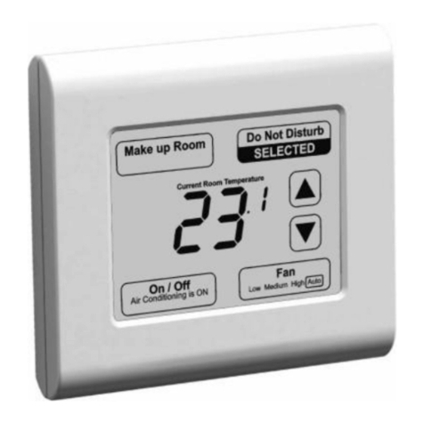
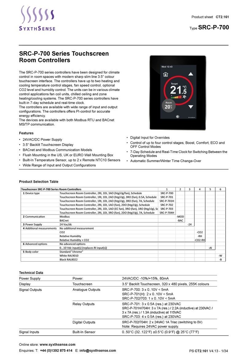
SyxthSense SYX66 Series User manual

SYX66x Commissioning Guide V1.10.3 300117
Page 1 of 61

SYX66x Commissioning Guide V1.10.3 300117
Page 2 of 61
Table of Contents
1. INTRODUCTION....................................................................................................................................................... 4
1.1 Important Information Regarding Product Safety..........................................................................................5
1.2 Notes on Disposal ...........................................................................................................................................5
1.3 INPUTS ............................................................................................................................................................6
1.4 ANALOGUE OUTPUTS .....................................................................................................................................7
1.5 OUTPUTS......................................................................................................................................................... 7
1.6 WEB BROWSER CONNECTION........................................................................................................................8
2 CONFIGURATION OVERVIEW.................................................................................................................................. 9
3 Equipment Selection and location........................................................................................................................10
3.1 Heating Application Example..............................................................................................................................10
3.2 HWS Application Example ..................................................................................................................................10
4 Connection Diagrams............................................................................................................................................12
4.1 Connection Diagram: Optimiser Mode...............................................................................................................12
4.2 Connection Diagram: Optimiser/Compensator Mode .......................................................................................13
4.3 Connection Diagram: Compensated Day/Night Reduced ..................................................................................14
4.4 Connection Diagram: Compensated Day/Night Frost Protection ......................................................................15
4.5 Connection Diagram: Y PLAN Mode ...................................................................................................................16
5 Access and Controller Configuration....................................................................................................................17
6. Controller Principles and Operational Features in detail .....................................................................................24
6.1 Optimum Start ..............................................................................................................................................24
6.2 Optimum Stop ..............................................................................................................................................24
6.3 Outside High Shutdown................................................................................................................................24
6.4 Flow Economy Mode ....................................................................................................................................25
6.5 Frost Protection............................................................................................................................................25
6.6 Pump Run On................................................................................................................................................25
6.7 Boiler Control................................................................................................................................................25
6.8 Valve Exercise ...............................................................................................................................................26
6.9 Pump Exercise...............................................................................................................................................26
6.10 Service Mode................................................................................................................................................26
6.11 Heating and Hot Water Time Extension .......................................................................................................26
6.12 Summer Winter Time Change and Leap Years .............................................................................................26
6.13 Space Temperature High Limit .....................................................................................................................26
7. Parameter Summary.............................................................................................................................................27
8. Menu Pages and Methods to Access Them..........................................................................................................32
8.1 Starting the Controller..................................................................................................................................32
8.2 Connecting with a laptop..............................................................................................................................32
8.3 Passcodes......................................................................................................................................................32

SYX66x Commissioning Guide V1.10.3 300117
Page 3 of 61
8.4 Commissioning Mode...................................................................................................................................32
8.5 Factory Defaults............................................................................................................................................32
9. Overrides Menu Pages..........................................................................................................................................33
9.1 Switch Page...................................................................................................................................................33
9.2 Values Page...................................................................................................................................................34
9.3 Times Tab......................................................................................................................................................35
10. Heating Menu Pages.........................................................................................................................................36
10.1 Switch Page...................................................................................................................................................36
10.2 Values Page...................................................................................................................................................40
10.3 Time Page .....................................................................................................................................................45
11. HWS Menu Pages..............................................................................................................................................46
11.1 Switch page...................................................................................................................................................46
11.2 Values Page...................................................................................................................................................47
11.3 Time Page .....................................................................................................................................................48
12. Boilers Menu Pages ..........................................................................................................................................49
12.1 Switch Page...................................................................................................................................................49
12.2 Values Page...................................................................................................................................................51
12.3 Times Page....................................................................................................................................................53
13. Connections Menu Pages .................................................................................................................................54
13.1 Switch Page...................................................................................................................................................54
13.2 Values Tab.....................................................................................................................................................55
14. Alarms and Management .................................................................................................................................56
14.1 Sensor Alarms...............................................................................................................................................56
14.2 Sensor Allocation Reset ................................................................................................................................56
14.3 Optimiser Alarm............................................................................................................................................56
15. Maintenance and Warranty .............................................................................................................................58
16. Using the colour touchscreen...........................................................................................................................58
17. FAQ ...................................................................................................................................................................60

SYX66x Commissioning Guide V1.10.3 300117
Page 4 of 61
1. INTRODUCTION
Note to Reader: This manual is to be used as an aid to assist in the commissioning of the SYX660, SYX661, SYX662,
SYX663 and SYX664 Controllers from SyxthSense. The SYX66x range of controllers have identical functionality
apart from the sensor types they work with. For the purposes of efficiency this one guide reflect all the above
controller types and to help reduce repetition the controller is hereon referred to as SYX66x.
TheSYX66xis asimplecontrollerwhichisdesigned
to suit the control needs of today’s smaller commercial and larger
domestic
properties. It can be configured control one, two or multiple boilers (via 0-10v sequencer), or provide burner
modulation. Valve and/or Boilers can be compensated. Plant control options are with optimumstart/stop
,
direct boiler,
direct valve or boiler and valve compensation. The heating circuit is easily configured for constant temperature as
required by adjustment of the heating curve.
A separate timed output channel is provided for the provision of hot water, the HWS relay option is required for this
output. The HWScontrol routines can beused independentlyorcombined with the boilers.
If combined with the boilers
then the option of boiler heat demand by the Hot Water is provided by an optional auxiliary digital input, this increases
energy savings.
Fast installation and operation are key features of the SYX66x. The controller has a base application that is adjusted
during the commissioning phase by simple parameter choices.
The use of practical default settings means that the
system is ready to control
a radiator system
with minimal adjustments. Additional
self-adapting features adjust the
control settings to the buildings performance.
An overridemenu(Panel Switch)allows you to override the control modewithout the need to
change any settings. If set
point and time settings of the unit is required these can be made using either the inbuilt display, optional remote
colour touchscreen, or the in-built web browser that is compatible with any Laptop or Smart Device.
The info button provides direct access to visual indication of all input and output status.
The Malfunction button allows the alarms to be seen and actioned
There is a user button to quickly acknowledge and clear Alarms
The simple user screen is text based using simple language and is backlit for easy use in poor plant room lighting.
The internal web browser allows local site and remote site monitoring/supervision. Users can interrogate relevant
parameters with 3 distinct user levels. Access levels are changed by entering the correct code between: Information
Level (default), Change Level, Set-up level.
Historical records of temperature are taken at regular
intervals and sensor are monitored for their operational
condition. Performance can be assessed and savings increased through better information and analysis. Simple
configuration and simple use are key features of the SYX66x.

SYX66x Commissioning Guide V1.10.3 300117
Page 5 of 61
1.1 Important Information Regarding Product Safety
Safety Instructions
This document contains information on installing and commissioning the product "SYX66x". Each person who carries
out work on this product must have read and understood this document. If you have any questions that are not
resolved by this document, you can obtain further information from the supplier.
If the product is not used in accordance with this document, the protection provided will be impaired.
Applicable regulations must be observed when installing and using the device. Within the EU, these include
regulations regarding occupational safety and accident prevention as well as those from the
VDE (Association for Electrical, Electronic & Information Technologies). If the device is used in other countries, it is
the responsibility of the system installer or operator to comply with local regulations.
Mounting, installation and commissioning work on the devices may only be carried out by qualified technicians.
Qualified technicians are persons who are familiar with the described product and who can assess given tasks and
identify possible dangers due to technical training, knowledge and experience as well as knowledge of the appropriate
regulations.
1.2 Notes on Disposal
For disposal, the product is considered waste from electrical and electronic equipment (electronic waste) and must
not be disposed of as household waste. Special treatment for specific components may be legally binding or
ecologically sensible. The local and currently applicable legislation must be observed.

SYX66x Commissioning Guide V1.10.3 300117
Page 6 of 61
1.3 INPUTS
Six temperature sensor inputs andtwodigitalInputsare available and are to be used
as follows.
The sensor characteristic type to be used is dictated by the controller part number:
Terminal
Pin
Function
Details
13&15
Pin 1
Outside Air Temperature
Sensor Part:
TEU
•
Outside economy
•
Compensation
•
Frost protection
14&15
Pin 2
Compensator Flow Sensor
Sensor Part:
TEAT Immersion
or TEP Strap-On
•
Heating Valve Compensation
Control
16&15
Pin 3
Boiler/Heating Return Sensor
Sensor Part:
TEAT Immersion
or TEP Strap-On
•
Return Pipe Frost protection
(Optional but strongly
recommended)
17&15
Pin 4
Boiler Flow Sensor
Sensor Part:
TEAT Immersion
or TEP Strap-On
•
One or two boiler control
•
Boiler compensation
•
Boiler high temperature alarm and
boiler cut out
31&33
32&33
Pin 5
Pin 6
Space Sensor 1
Space Sensor 2
Sensor Part:
TEHR
•
Optimum Start/Stop
•
Averaging (when 2 used)
•
Day economy
•
Room Influence
•
Space Frost protection
27&28
Pin 9
Remote Day Extend button for
heating (and HWS if selected)
LAP5
•
Closed contact extends the time
schedule for as long as the contact
is closed. Heating controls to day
requirements as required, or not.
29&30
Pin 10
Auxiliary Switch Input
(Close switch to activate)
•
Multi-function input
•
Installer can select one of the
following uses :
1.Frost Mode (Holiday Switch)
2.HWS Demand (Boiler Set point Request)
3.Summer Switch
4.Underfloor Heat Demand
Special Note:
KP10 sensors used with the SYX660 controller are polarity sensitive. The sensors have a +ve and –ve connection.
When connecting these sensors to the SYX660 please connect –ve side of the sensor to terminals 15 or 33 and use
the +ve to the remaining connection as stated above. Other controller types and their sensors are not polarity
sensitive and so have no requirement for special attention.

SYX66x Commissioning Guide V1.10.3 300117
Page 7 of 61
1.4 ANALOGUE OUTPUTS
One 0-10v output is available. It can be set to offer one of three services.
Terminal
Pin
Function
Details
34 0-10
36 Gnd
Pin 7
User Selectable Output
(Configured in Connections
Menu)
•
0-10v signal for VT Valve
•
0-100% boiler demand signal or
sequencer demand signal
•
0-10v scalable boiler set point signal
(Only 1 option can be selected.)
Note:
SYX controllers do not provide 24vAC or 24vDC power. External supplies may be required for your project. When
using external 24v AC/DC supplies the 0v side must be connected with the GND connection on either Terminal 18
or 36.
1.5 OUTPUTS
All the relay outputs are 230Vac 5A rated SPST. The switch feeds can be Volt Free, 230v or 24v and all switched
feeds derived from an external source that the installer must connect as required. The HWS output requires an
auxiliary relay to function (see HWS relay wiring diagram). The outputs are allocatedas
follows:
Terminal
Pin
Function
Details
35 0v
19 +ve
Pin 8
Hot Water Relay
(Connect HWS relay A1/A2
across 19 and 35)
•
See wiring, requires use of an SYX66X-1RM
relay. VFC Timed output either direct to HWS
Heater or via a relay/contactor.
3&4
Pin 11
Boiler No. 1
•
VFC Control output either direct to boiler or via
a relay/contactor
5&6
Pin 12
Boiler No. 2
•
VFC Control output either direct to boiler or via
a relay/contactor
7&8
Pin 13
Pump
OR
Optimiser Mode Plant
Start/Stop
•
VFC Control output either direct to Pump
enable or via a relay/contactor
•
Can also be used to drive a twin pump set via
the PMPCO Auto change over module from
SyxthSense
•
Also used as the Optimiser Plant Start/Stop
signal when Optimiser Only mode selected
9&10
Pin 14
VT Valve Open
OR
Y Plan Mode HTG Call
•
Actuator open signal VFC, 230V or 24v
reversing actuator (supply to be provided)
•
HTG Enable Signal (YPLAN Mode only)
11&12
Pin 15
VT Valve Close
OR
Y PLAN Mode HWS Call
•
Actuator close signal VFC, 230V or 24v
reversing actuator (supply to be provided)
•
HWS Enable Signal (YPLAN Mode only)

SYX66x Commissioning Guide V1.10.3 300117
Page 8 of 61
1.6 WEB BROWSER CONNECTION
Customer Interface is possible using a Web Browser, Smart Phone (with SYX66x connected to a network with Wi-Fi
access). Users can quickly:
•
Check current status of control system
•
Change User level
•
Change of settings
•
View historic information
•
Time Schedule and Holiday Planning
•
Configuration of all the controller options
•
Remote overrides and time extensions
•
Observe Live Controller Operation
IP: 192.168.1.99
SM: 255.255.255.0
DG: 192.168.1.1
Users must ensure that their chosen device is configured to be on the same network range to ensure that a
connection can be made. For more information please see the Laptop Fixed IP config video on SyxthSense Video
Resource Library
http://www.syxthsense.com/video_resources

SYX66x Commissioning Guide V1.10.3 300117
Page 9 of 61
2CONFIGURATION OVERVIEW
The SYX66x controller is configured by the installer to provide control of simple heating plant. The SYX66x is
configured in specific phases. The phases are: Overrides, Heating, Hot Water, Boilers and Connections. The heating and
hot water functions areindependent of each other but may share some featuressuch as the Boilers and Overrides. These
options allow the controller to be easily adapted to best suit particular plant and building applications.
The selection
and behavior of an option is also further determined by the user
settings inside the associated option itself. Thisallows
a logical procedure through the controller configuration and fine tuning of specific sections in turn.
The heating mode options inthe
controller that can be selected during set-up are:
•Optimum Start/Stop of a plant start signal with Space Frost Protection and Space High Limit Protection
•Optimiser Compensator of valve and/or Boiler(s) with Frost Protection
•Day Compensation of Valve and/or Boiler(s) with Night Reduced Compensated Heating
•Day Compensation of Valve and/or Boiler(s) with Night Frost Protection
•V1.10 Introduces a Y Plan Mode option, the Heating can be optimised if required and the HWS will be demand
controlled to enhance older systems.
•V1.10 Introduces Underfloor Heat Demand option for the heating circuit of underfloor manifolds.
On start-up, the settings have been pre-set to
give sensible values suitable for a Radiator VT Heating System.
All of the above Heating Modes are available with a Hot Water Service output that also has the following options:
•Boiler Linked with adjustable Primary Set point
•Boiler Linked with adjustable Primary Set point and HWS Demand control (Pin 10)
•Independent Hot Water Heating Time Channel.
•Option to Link the Hot Water to the Heating Extension Button (Pin 9)

SYX66x Commissioning Guide V1.10.3 300117
Page 10 of 61
3Equipment Selection and location
3.1 Heating Application Example
Boiler
1
Boiler
2
S
F
O
S
Valve
O
Outside Air Sensor located on North Facing wall shaded from direct sunlight
F
R
Boiler Flow Sensor located in common flow pipe from boilers.
Return Sensor located in main return pipe to boilers on system side.
V
Variable Temp Flow Sensor located in main flow pipe to radiators after pump
S
Space Sensor located in heated room that is always used for occupant purposes
Valve
Mixing Valve located in system flow, allows mixing with return from heating load
Pump
Pump
Heating Pump located in heating flow, circulates heat around the heating load
V
R
R
R
Locate the Return Sensor on Load side if HWS is boiler linked so that heating load is
protected during periods of non-use
System Side
Load Side
S
Second Space Sensor located in Heated Room that offers a balancing view of heating
effect to the building.
Room 3
Room 1
Room 2
Exterior Wall

SYX66x Commissioning Guide V1.10.3 300117
Page 11 of 61
3.2 HWS Application Example
Boiler
1
F
R
Boiler
2
C
Valve
C
The HWS Control Circuit is enabled from an IO-1RM relay connected on 30&35 (Pin 8).
This output may also be used to provide a control signal to the HWS Circulation Pump
enable circuit (by others).
The HWS Menu will be “Boiler Linked” for the above scheme.
The Cylinder Thermostat is controlling the valve actuator. The Actuator opens to allow
water through the heating coil. If the Auxiliary input is configured to “HWS Demand”
the Actuator drives open and an auxiliary switch closes the contact to 29&30 (Pin 10).
This requests the boilers to run to the Primary Set point. When the HWS is satisfied
the thermostat opens and this closes the valve. The valve contact then opens and the
boiler set point is relaxed. If there is no heating demand then the boilers will be
switched off. The connection to the controller Pin 10 must be volt free.
If the HWS Demand option is not configured then the boilers will run at the HWS
primary Set point until the HWS Time Period Ends.
F
R
Boiler Flow Sensor located in common flow pipe from boilers.
Return Sensor located in main return pipe to boilers on system side.
HWS Storage
Calorifier
HWS Circ
Note: There is no HWS Temperature Control provided. There is only Boiler demand
control. The HWS Control is by external controls. The HWS Output remains On for the
duration of time schedule or HWS override. The Auxiliary input simply shifts the Boiler
output to the higher of the Heating or HWS Primary Set point. (Subject to Max Boiler
Flow Temp)
Note: HWS Option Relay is required

SYX66x Commissioning Guide V1.10.3 300117
Page 12 of 61
4Connection Diagrams
4.1 Connection Diagram: Optimiser Mode
•One Space Sensor is required for the optimiser to function. The second is optional.
•The HWS Control and its options are optional.
•The boilers only serve the HWS Function (if linked) in Optimiser Only application
•The Optimiser Start/Stop Signal is provided from the Plant Start terminals 7&8, wire your switch feed into Terminal 7
and Plant Start Connection out from Terminal 8
•Time Extend and Holiday features apply
•0-10v Output option supported for the boiler demand or boiler set point control.
•VT Valve Control not supported
•Plant Start Connection is optimised on and optimised off as default. The plant connection remains closed through the
occupied period. Optimum Off can be disabled meaning plant then turns off at end of occupied period on space High
Temperature.
•Outside Air Sensor can be fitted to provide Outside High Temp Shutdown if required.
•Outside sensor will display as 0°C if not connected or if sensor is faulty when in Optimiser Mode.
•If boiler control is required then a boiler flow sensor is required
•If plant room is exposed and return frost is required please connect a return sensor
•Observe KP10 sensor type polarity and GND connection see note Page 6
SYX 66x
1 2
3 4
5 6
7 8
9 10
11 12
13 14 15 16 17 18
12vDC 0v
Space 1
Space 2
L
N
Plant
27 28 29 30 31 32 33 34 35 36
-ve
-ve

SYX66x Commissioning Guide V1.10.3 300117
Page 13 of 61
4.2 Connection Diagram: Optimiser/Compensator Mode
•One Space Sensor is required for the optimiser/compensator to function. The second is optional.
•The HWS Control and its options are optional. IO-1RM is required if HWS output to be used.
•The boilers serve the Heating and HWS Function (if linked)
•Boiler Flow and Return Sensors are needed for boiler control
•VT Flow Sensor required for Valve Compensation Control
•Time Extend and Holiday features apply
•0-10v Output option supported for the VT Valve, boiler demand or boiler set point control.
•Heating is optimised on and optimised off as default. Optimum Off can be disabled meaning plant then turns off at
end of occupied period on Space High Temperature.
•Observe KP10 sensor type polarity and GND connection see note Page 6
1 2
3 4
5 6
7 8
9 10
11 12
13 14 15 16 17 18
12vDC 0v
Space
1
Space
2
L
N
Boiler 1
Boiler 2
Pump
Open
Close
HWS
IO-
1RM
Outside
Temp
Heating
Return
Boiler
Flow
Optional
items
VT Flow
0-10v
Out
Day
Ext
Aux
Input
27 28 29 30 31 32 33 34 35 36
SYX66x
-ve
-ve

SYX66x Commissioning Guide V1.10.3 300117
Page 14 of 61
4.3 Connection Diagram: Compensated Day/Night Reduced
•Space Sensors are optional. If fitted can provide room influence of heating flow temperature
•Room Sensor is needed if room frost protection is required during holiday periods.
•The HWS Control and its options are optional. IO-1RM is required if HWS output to be used.
•The boilers serve the Heating and HWS Function (if linked)
•Boiler Flow and Return Sensors are needed for boiler control
•VT Flow Sensor required for Valve Compensation Control
•Time Extend and Holiday features apply
•0-10v Output option supported for the VT Valve, boiler demand or boiler set point control.
•Heating is time controller between day and night levels. Day Extend will hold day levels.
•Observe KP10 sensor type polarity and GND connection see note Page 6
1 2
3 4
5 6
7 8
9 10
11 12
13 14 15 16 17 18
12vDC 0v
Space
1
Space
2
L
N
Boiler 1
Boiler 2
Pump
Open
Close
HWS
IO-
1RM
Outside
Temp
Heating
Return
Boiler
Flow
Optional
items
VT Flow
0-10v
Out
Day
Ext
Aux
Input
27 28 29 30 31 32 33 34 35 36
SYX66x
-ve
-ve

SYX66x Commissioning Guide V1.10.3 300117
Page 15 of 61
4.4 Connection Diagram: Compensated Day/Night Frost Protection
•Space Sensor provides room influence of heating flow temperature during the day
•Room Sensor provides frost protection is required during holiday periods.
•Two Room sensors may be fitted to provide an average temperature.
•The HWS Control and its options are optional. IO-1RM is required if HWS output to be used.
•The boilers if required serve the Heating and HWS Function (if linked)
•Boiler Flow and Return Sensors are needed for boiler control
•VT Flow Sensor required for Valve Compensation Control
•Time Extend and Holiday features apply
•0-10v Output option supported for the VT Valve, boiler demand or boiler set point control.
•Heating is time controller between day and night levels. Day Extend will hold day levels.
•Observe KP10 sensor type polarity and GND connection see note Page 6
1 2
3 4
5 6
7 8
9 10
11 12
13 14 15 16 17 18
12vDC 0v
Space
1
Space
2
L
N
Boiler 1
Boiler 2
Pump
Open
Close
HWS
IO-
1RM
Outside
Temp
Heating
Return
Boiler
Flow
Optional
items
VT Flow
0-10v
Out
Day
Ext
Aux
Input
27 28 29 30 31 32 33 34 35 36
SYX66x
-ve
-ve

SYX66x Commissioning Guide V1.10.3 300117
Page 16 of 61
4.5 Connection Diagram: Y PLAN Mode
•One Space Sensor is required for the optimiser to function. The second is optional.
•The HWS is enabled from 11 & 12
•The boilers link option must be selected and the Aux input set to HWS Demand
•Time Extend and Holiday features apply
•1, 2 boilers or 0-10v outputs can be used for boilers
•HWS Thermostat is Volt Free Contact
•Room Sensor is correct sensor type only. Do not connect a room thermostat.
•VT Valve Control not supported
•Plant Start Connection is optimised on and optimised off as default. The HTG connection remains closed through the
occupied period unless space limit reached. Optimum Off can be disabled meaning plant then turns off at end of
occupied period on space High Temperature.
•Outside Air Sensor can be fitted to provide Compensated Flow from Boilers and Outside High Temp Shutdown if
required.
•Outside sensor will display as 0°C if not connected.
•If boiler compensation control is required then a boiler flow sensor is required
•If plant room is exposed and return frost is required please connect a return sensor
•Observe KP10 sensor type polarity and GND connection see note Page 6
SYX 66x
1 2
3 4
5 6
7 8
9 10
11 12
13 14 15 16 17 18
12vDC 0v
Space 1
Space 2
L
N
Pump
27 28 29 30 31 32 33 34 35 36
HTG
HWS
Boiler 1
Boiler 2
HWS Stat
-ve
-ve

SYX66x Commissioning Guide V1.10.3 300117
Page 17 of 61
5Access and Controller Configuration
To Set-up the controller, the user must be logged into the SYX66x at level 2.
To access the Logon Screen on the controller please Press and Hold the ESC button for 5 Seconds.
Select User 2
The passcode for Set-up level is 0112
Turn and Press the Wheel to select the above code
Once you have 0112 on the Controller press the Select Button to enter it
To access the Logon Screen using the browser or the TPC Touchscreen select the Logon Button in the bottom corner
and follow the same instructions as above but using the keys on the screen. Press enter on the screen to enter the
value.
Once at this User Level the Set-Up Menu options are available to tune the controller to the application you have.
Each menu shown on the controller interface (shown below) has application Set-Up features inside.
The controller offers a menu structure and the navigation can be made using the controller interface or the web
browser. The controller offers two different browser options as shown below with and without /mo/ after the IP address
of the controller and either can be used:
Above: example 192.168.1.99/mo/
Above: example using basic browser on 192.168.1.99

SYX66x Commissioning Guide V1.10.3 300117
Page 18 of 61
Once logged into the controller at Level 2 select each menu in turn and configure the Set-Up options as discussed
below. Only the Set-up options should be configured at this time, do not worry about the other parameters as these
may not be required.
The following tables show the application configuration settings for each Set-Up menu option.
For example, Select Overrides then navigate to the menu Option Set-Up. Complete as required then move onto the
Heating Menu and navigate to the Set-up option etc etc.
After the Set-Up options have been checked you can go back into the individual menus and adjust the other
associated parameters as required to get the best application performance. These are listed in the Parameter
Summary page 25.
Set-Up Options inside the Override Menu
HINT: Heating, HWS, Boilers, Overrides etc each have set-up options
Set-Up Options inside the Heating Menu

SYX66x Commissioning Guide V1.10.3 300117
Page 19 of 61
All of the Set-Up Options will now be discussed in turn:
Menu
Set-Up Option
Description
Options
Overrides
HWS Extend
If the time extension input
(Pin 9) is closed for heating
extend, do you want the
HWS to also extend?
Enabled (Default) –When the switch is closed
the HWS will be time enabled in addition to the
heating. (Unless Summer mode is active and
only the HWS will be enabled)
Disabled –The HWS is not linked to the
Heating Override on Pin 9.
Auxiliary Switch
Input
You can chose the function
of this input to suit your
scheme. Only one use can
be selected. The switch
connected to Pin 10 must
be closed to activate. When
the switch opens the
controller returns to Auto.
Frost Mode (Default) –Fixes the controller
into Frost protection level control. The HWS is
also disabled.
HWS Demand –If the HWS Time channel or
override are on this input must be closed to
request the boiler to heat the HWS to the
Primary Set Point.
Summer Mode –Fixes the controller into
Summer Mode –this puts the Heating into
Frost Mode but the HWS remains active. If
controller is in Summer Mode and Time
extension button if pressed controller will bring
on the HWS Only.
Note: HWS control if available is always
recommended to save energy. Frost and
Summer Mode can be set using the
controller mode switch in the Overrides
Menus.
Underfloor Demand –Holds the VT Valve
and Heating Demand for the boilers until the
Underfloor heating is in demand

SYX66x Commissioning Guide V1.10.3 300117
Page 20 of 61
Heating
Heating
Mode
Select the Mode of control that best
suits the occupation pattern and use
of the building
Night Setback –Uses a compensated curve for
Day and a reduced heating curve for night
periods. Typically used in 24hr occupied facilities.
Typically used when replacing older controllers
like CSC with time clock. Also used automatically
if the Room Sensor reading is not available when
in the Opt/Comp mode.
Opt/Comp –Optimised compensation typically
used in part occupied buildings such as schools or
offices. Used when replacing older products like
CSMC/DC1100/DC1400CMC/RVL45/Aquatrol
Timed On/Off –Used when optimisation is not
possible/required and night setback is not
required. Can be used when replacing older
controllers like Satchwell CSC
Optimiser –Used to start/Stop external systems
based on heat up rates and cool down rates.
Typically used when replacing older products like
Satchwell SVT
Opt YPLAN Mode –Configure the controller to
replace older Y Plan systems. Optimise the
heating and allow more energy saving by
compensating the boiler when the HWS is
satisfied.
VT Set point
The controller can adjust the heating
curve between the min and max limits
configured based on the room
conditions. This is otherwise known
as Room Influence.
Non-Adaptive (Default)
Self-Adaptive
Optimum Off
You can allow the controller to turn the
heating off early subject to the time
schedule, space temperature and
cooling down rate of the building
being aligned. Sometimes Optimum
off is not required due to fan heaters
or AHU being on the same pipe circuit.
Enabled (Default)
Disabled
HWS Priority
If the boilers are linked to the HWS
and the HWS Control option is
selected you can allow the HWS to
have priority over the heating system
given certain conditions or site
limitations. The method of gaining
priority is either to close the VT Valve
for a period of time or to turn the
heating pump off for a set period. E.g.
Can be used when boilers struggle to
heat all services at the same time.
No Priority (Default)
On Valve
On Pump
This manual suits for next models
5
Table of contents
Other SyxthSense Controllers manuals
Popular Controllers manuals by other brands

Delco Remy
Delco Remy 37MT Diagnostic Procedures Manual

Lenze
Lenze AC Tech M3103S Installation & operation manual

Blue Point Engineering
Blue Point Engineering Wizard - 11 instruction manual

ABB
ABB PP10 Operating instructions manual

Competition Electronics
Competition Electronics Z86G operating instructions

Dell
Dell PowerConnect W-620 installation guide