SyxthSense Ltd
Copyright © 2007 SyxthSense Ltd. All rights reserved - 1/2007
PS SN1.123 - 2/2
Online store: www.syxthsense.com
Enquiries: T: 0870 20 80 100 F: 0870 20 80 200
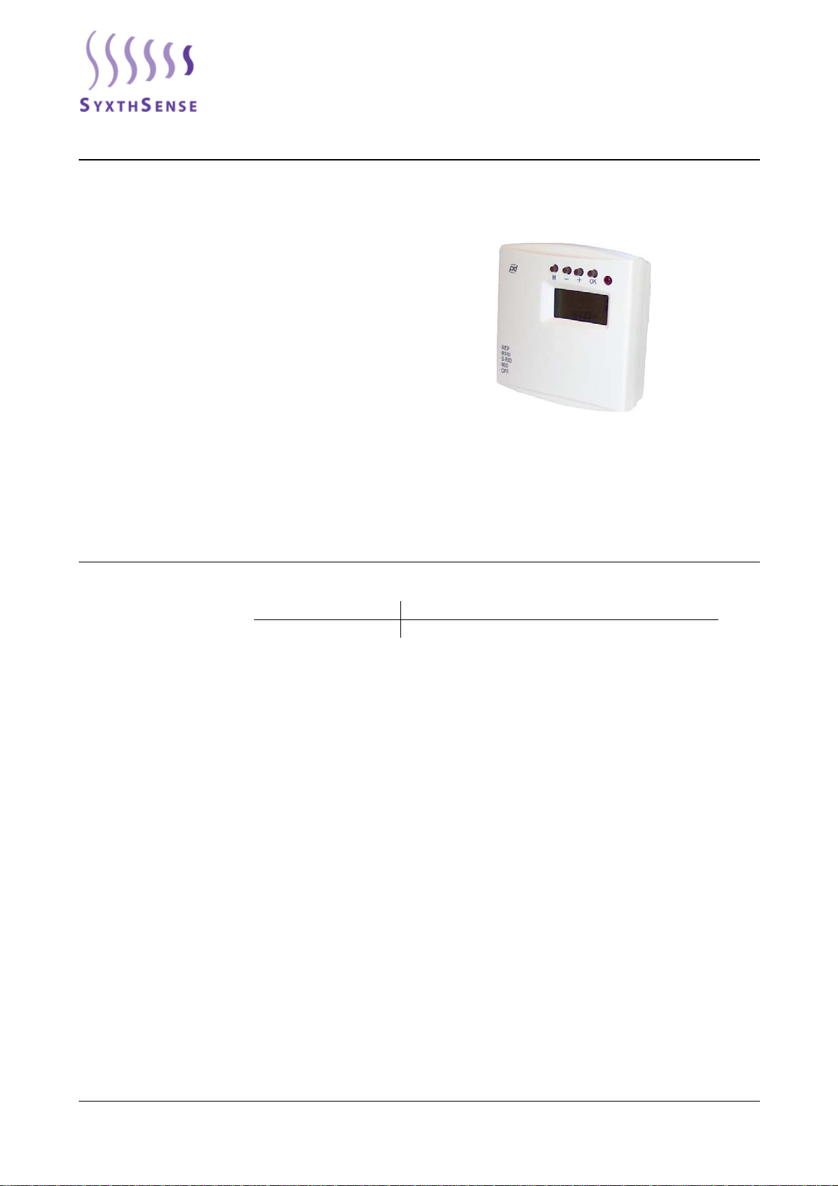
Operating Instructions The FLSER commissioning tool can be used for setting the TEFL sensor network address (MID -
Master ID and SID - Sensor ID). Master ID is the address of the FLTA unit (this is set through the
built-in display of the FLTA). Sensor ID is the unique address for each sensor in the FLTA network.
The FLSER tool can also be used to address the FLREP repeater. Each repeater needs to be
associated with the Master ID (MID) and Repeater ID (RID; 1 to 8). The Master ID is the network
address of the FLTA unit associated with the repeater. Up to 8 repeaters can be used with a FLTA.
1. Commissioning of TEFL room unit with FLSER tool
OFF
MID
S-RID
RSSI
REP
2. Commissioning of FLREP repeater with FLSER tool
OFF
MID
S-RID
RSSI
REP
3. Signal strength measuring with the FLSER tool
OFF
MID
S-RID
RSSI
REP
4. FLSER tool in the repeater emulation
OFF
MID
S-RID
RSSI
REP
a) In the switch position MID the TEFL room unit can be connected to the wanted FLTA receiver (1-
16) by using the – and + buttons on the top of the display. (Picture 1)
b) Choose the switch position S-RID to define the TEFL room unit’s own ID (SID 1-99) (picture 2)
c) Press the ”OK” button and on the display appears flashing text ”WAIT”
d) Remove the battery from the chosen TEFL room unit for a moment and put it back. This must be
done in 30 seconds, otherwise the FLSER tool goes back to the normal stage.
e) When the chosen TEFL room unit starts up and the programming has been successful, there
appears a text OK to the display. Also the LED’s of TEFL room unit and FLSER tool will flash 5
times simultaneousl
.
a) In the switch position RSSI the FLSER tool can be used for the measuring of signal strength
NOTE! When the switch is in the RSSI position, the FLTA receiver ends the normal service of the
network. There appears also a text “ON CARE” to the FLTA receiver’s display. FLTA receiver goes
back to its normal stage after 30 seconds, when the RSSI position is switched off. During the “ON
CARE” stage, it is possible that the TEFL room units go to the energy saving mode. The TEFL room
units go back to the normal stage 5 minutes after the FLTA receiver is back on its normal stage.
b) FLSER tool shows now on its display the intensity of its own signal strength (upper reading) and
the signal strength measured by the FLTA receiver (lower reading)
dequate signal strength is reached with values 2-9, if the value is lower than 2 it is recommended
to use the FLREP repeater between the room units and the receiver.
NOTE! FLSER tool shows the direct intensity of the signal strength between the FLTA receiver and
the FLSER tool. FLSER tool doesn’t use the possibly installed FLREP repeaters to the signal
strength measuring.
In the switch position REP the FLSER tool can be used to emulate the FLREP repeater. During this
application there shouldn’t be installed any FLREP repeaters. The feature of this application is to
ease up the installation of actual FLREP repeater and to find a suitable location for it.
For example, if the installation location doesn’t have adequate signal strength, the FLSER tool can
be used to emulate the position of FLREP repeater and the adequate intensity can be checked b
using the FLTA receivers own signal strength measuring. By these measures can be assured that
the signal strength is adequate (RSSI 2-9)
NOTE! The repeater emulation will deplete the battery of FLSER tool in 100h, therefore the FLREP
repeaters will need 24 V ad/dc supply
b) Choose the switch position S-RID and press button M on the top of the display. After that there
appears a text RID to the display and the repeater ID 1-8 can be chosen by using the – and +
buttons.
c) Press the ”OK” button and on the display appears flashing text ”WAIT”
d) Connect the supply voltage 24 V ac/dc to the FLREP repeater. This must be done in 30 seconds,
otherwise the FLSER tool goes back to the normal stage.
e) When the chosen FLREP repeater starts up and the programming has been successful, there
appears a text OK to the display. Also the LED’s of FLREP repeater and FLSER tool will flash 5
times simultaneously.
a) Select switch position MID to set the repeater Master ID (ID of the FLTA). Use + and - buttons on the
top of the display to set the required MID (Master ID)