T-Drill S-80 User manual

INSTRUCTION MANUAL
COLLARING MACHINE

INSTRUCTION MANUAL
2
Version
5340418EN
27.06.2018 / MT
PRELIMINARY EDITION
Instrucons for the use and maintenance of the T-Drill Collaring machine S-80.
Copyright © 2018 T-DRILL Oy. All rights reserved. This manual, or parts thereof, may not be reproduced in any form or by
any means, nor translated into any other language without a wrien permission of T-DRILL Oy
Is has been our aim to elaborate this instrucon book with the greatest possible care and aenon. The accuracy of the in-
formaon has been carefully checked during the preparaon of the manual. Should any subsequent modicaons be made
to the product, we decline liability for erroneous or incomplete informaon.
Manufacturer:
OY
Ampujane 32 / P.O BOX 20
FIN-66401 Laihia, Finland
Tel.Int +358-6-4753 333
Telefax: +358-6-4753 300
www.t-drill.
Sales and Service in the USA:
INDUSTRIES, INC.
1740 Corporate Drive, Suite 820,
Norcross, Georgia 30093, USA
Phone: 800-5542730
Fax#: 770-925-3912
www.t-drill.com
Your local dealer is:

COLLARING MACHINE
3
S-80
CONTENTS
................................................................... 5
1.1. General .......................................................................................................................... 5
1.2. Symbols for warning and danger used in this manual................................................... 5
1.3. Symbols and warnings used in the TCC-28 machine ..................................................... 6
1.4. Personal protecve equipment for the operator .......................................................... 7
............................................................................................ 7
..............................................................
3.1. Introducon................................................................................................................... 8
3.2. The purpose of the machine ......................................................................................... 8
3.3. Technical specicaons ................................................................................................. 8
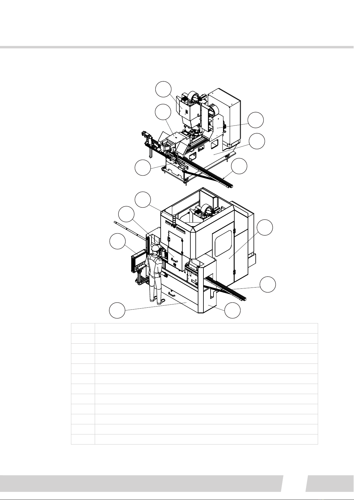
3.4. Main parts of the machine ............................................................................................ 9
3.4.1. Technical features of main parts .......................................................................... 10
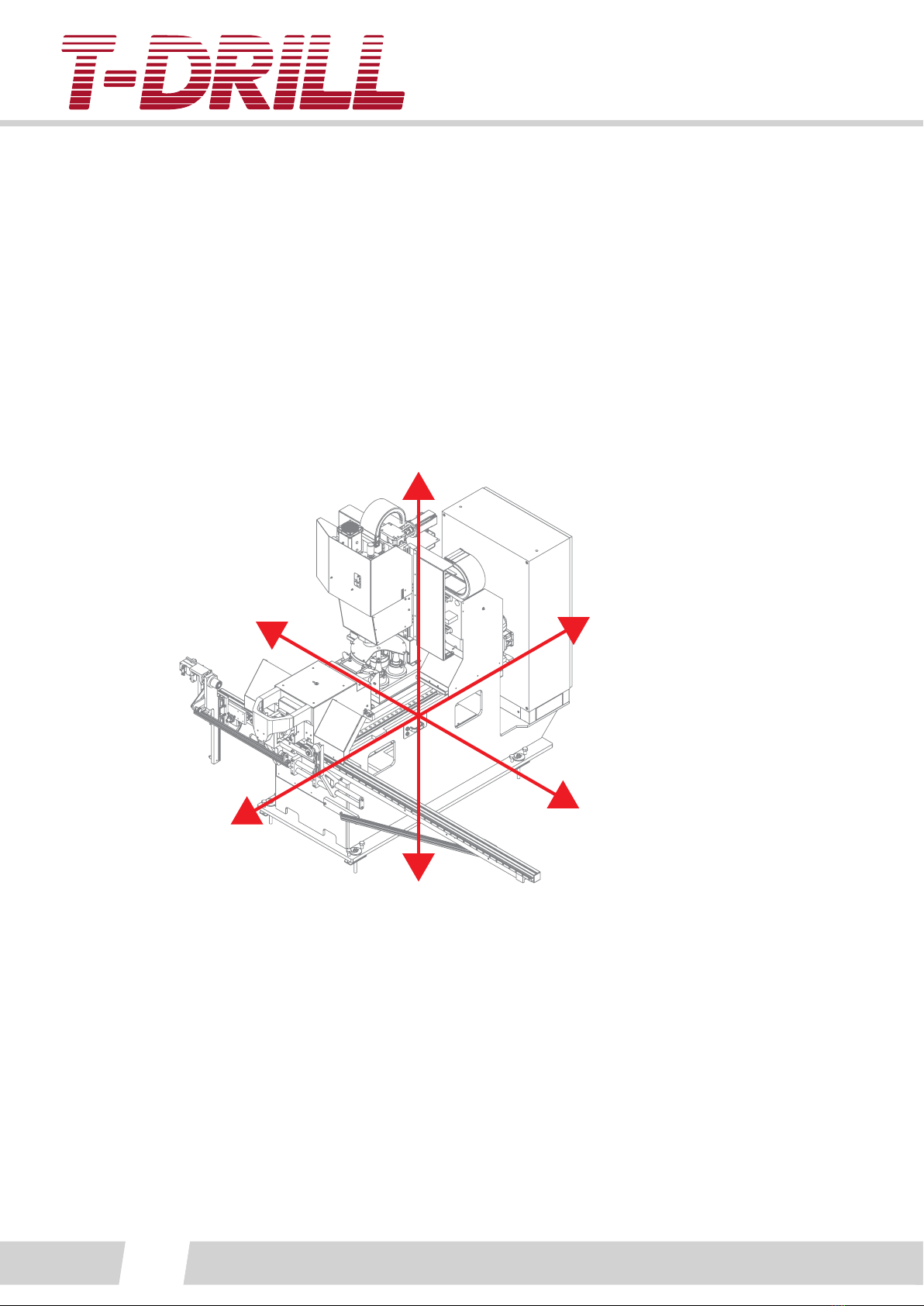
3.5. Axis direcons of the machine ...................................................................................... 10
.................................................................................... 11
4.1. Transport and locaon................................................................................................... 11
4.2. Liing instrucons......................................................................................................... 11
.................................................................................................................... 12
5.1. Ambient condions ....................................................................................................... 12
5.2. Layout of the S-80 Collaring machine............................................................................ 13
5.3. Installaon of the light curtains (oponal equipment).................................................. 15
5.4. Connecon of the machine to the sources of energy ................................................... 16
5.4.1. Connecon to the electricity network .................................................................. 16
5.4.2. Connecon to the compressed air system............................................................ 17
5.5. Start-up checking........................................................................................................... 17
..............................................................
6.1. Descripon of the control devices................................................................................. 18
6.1.1. Main switch.......................................................................................................... 18
6.1.2. Clamp remote control CB3 ................................................................................... 18
6.1.3. Control panel........................................................................................................ 19
6.2. Descripon of the user interface screens...................................................................... 20
6.2.1. Start-up screen ..................................................................................................... 20
6.2.2. Main screen.......................................................................................................... 21
6.2.2.1. Bar charts screen ........................................................................................... 24
6.2.2.2. Menu screen .................................................................................................. 24
6.2.2.2.1. Programs ................................................................................................. 25
6.2.2.2.2. Manual screen.......................................................................................... 27
6.2.2.2.3. Automac screen ..................................................................................... 29
6.2.2.3. Sengs screen ............................................................................................... 30
6.2.2.3.1. Machine sengs ...................................................................................... 31
6.2.2.3.2. Process sengs ........................................................................................ 32
6.2.2.3.3. Tool sengs.............................................................................................. 34
6.2.2.3.4. Tool magazine .......................................................................................... 40
6.2.2.3.5. Posions ................................................................................................... 42
6.2.2.3.6. Servo motors ............................................................................................ 43

INSTRUCTION MANUAL
4
6.2.2.3.7. References ................................................................................................ 44
6.2.2.4. Alarms screen................................................................................................. 45
6.2.2.5. Users management........................................................................................ 45
6.2.2.6. Counters screen.............................................................................................. 46
6.2.2.7. I/O data screen .............................................................................................. 46
6.3. Stopping the machine ................................................................................................... 47
6.3.1. Emergency stopping............................................................................................. 47
6.3.2. Normal stopping of the S-80 unit ......................................................................... 47
6.4. The lubricaon of the collaring process ........................................................................ 48
6.5. Tools .............................................................................................................................. 49
6.5.1. Milling tool .......................................................................................................... 49
6.5.2. Collaring / trimming tool...................................................................................... 50
6.5.2.1. Collaring tool measuring device 5560252...................................................... 51
6.5.3. Drilling collaring tools .......................................................................................... 54
6.5.4. Tool cone jig 6560093........................................................................................... 55
6.5.5. Fork tool 6560094 ................................................................................................ 55
6.5.6. Reference posion seng tools ........................................................................... 56
6.6. Manual feed table ......................................................................................................... 57
6.7. Control tower signal lights............................................................................................. 59
......................................................................................
7.1. Machine general setup.................................................................................................. 60
7.1.1. Collaring tool setup ............................................................................................. 60
7.3. Tool magazine................................................................................................................ 62
................................................................................................................. 63
8.1. Clamping device maintenance and adjustment ............................................................ 65
8.2. Collaring unit maintenance and adjustment ................................................................. 66
8.2. Collaring tool maintenance ........................................................................................... 68
8.2.1. Dismantling and reassembling of the collaring tool............................................. 68
8.2.2. Replacing the collaring pins ................................................................................. 69
8.2.2.1 Smaller S-80 heads : Fork tool 6560094.......................................................... 71
8.3. Drilling collaring tool maintenance................................................................................ 71
8.5. Screwjack and ball screw drive maintenance................................................................ 77
8.6. Oil collectors.................................................................................................................. 77
8.7. Spindle lubricaon maintenance................................................................................... 78
.............................................................................................................
.....................................................................................................................
11. Safety data regarding the lubricants.............................................................................
12. Ordering spare parts ....................................................................................................
13. Appendix .....................................................................................................................
13.1. Capacity table.............................................................................................................. 85
13.2. Pilot hole table ............................................................................................................ 87

COLLARING MACHINE
5
S-80
1. NOTES ON THE USE OF THE INSTRUCTION MANUAL
1.1. GENERAL
This manual contains the instrucons for use, maintenance and seng of the T-DRILL
S-80 Collaring machine.
Before proceeding with the installaon or operaon of S-80 collaring machine, read the
general safety instrucons in chapter 2
If the S-80 collaring machine forms part of a system supplied by T-DRILL, then also the
general safety instrucons related to the other appliances should be studied before use.
¨NOT!¨
MANUAL
LDA¨GTR! May cause a serious accident or even death if the correct
precautions have not been taken.
a
have not been taken.
¨NOT!¨

INSTRUCTION MANUAL
6
1.3.
Read the instrucon manual aenvely before carrying out
installaon, operaon, seng or maintenance of the machine.
Electric box. Danger may be caused by electric installaon.
Sharp edges!
Be extremely cauous when handling this area of the machine.
Don’t look into the pipe during the process relang to the collar.
Don’t put your hands on the tube line under the machine or in
the end of the machine during process.
Mind the rotang tool.
Warning! Moving parts. Be extremely cauous when handling
this area of the machine.
Use hearing protector when operang with the machine.
Use safety shoes when handling pipes and the tools of the
machine.
Use protecve glasses when operang with the machine.
Always use protecve gloves when handling the tools - the
cung edges and the lubricant used may cause wounds and
inammaons.

COLLARING MACHINE
7
S-80
1.4. PERSONAL PROTECTIVE EQUIPMENT FOR THE OPERATOR
Always wear the appropriate personal protecve equipment, and use extreme cauon
when operang the machine.
The local safety guidelines and regulaons are to be followed for safe operaon. The
T-Drill instrucon manual will not repeal the federal, state and local regulaons.
Use overalls when operang the machine.
2. GENERAL SAFETY INSTRUCTIONS
Read the instrucon manual aenvely before installaon, operaon or maintenance of
the machine.
The T-DRILL S-80 is to be used only for collaring in the specic way as described in this
manual.
When operang the T-DRILL S-80 it must be fastened on the oor.
Do not exceed the capacity of the machine.
Before removing or mounng a collaring head or a clamp, the electric current supply
must be disconnected by pushing the power OFF (O) buon in the front panel.
Disconnect power before carrying out any maintenance or repair inside the machine.
Do not keep any loose objects or tools on the machine.
Make sure the venlaon is sucient.
Always use protecve glasses when using the S-80 unit.
Always wear protecve gloves when handling the collaring tool.
Study also the safety data sheet concerning the lubricant which is supplied with the
machine.
When pressing the Emergency switch (STOP-buon) all funcons of the S-80 collaring
machine are immediately interrupted.
Aer installaon of the machine and before using the funcons of the S-80 collaring unit,
carry out the measures described in chapter “start-up checking”.
¨NOT!¨

INSTRUCTION MANUAL
8
3.1. INTRODUCTION
The construcon of the unit consists of the covers, collaring machine body, spindle, a
clamping mechanism and posioning table.
The machine body and the spindle absorb the collaring stress. The feed stroke of the
spindle is servo controlled, which assures the achievement of an opmal eciency and a
great precision. The spindle rotaon is accomplished by means of a ming belt, directly
by the driving motor.
The S-80 collaring machine has safety devices in accordance with the CE requirements.
All this to guarantee that the T-DRILL S-80 unit is reliable even in heavy duty industrial
use.
3.2. THE PURPOSE OF THE MACHINE
The S-80 unit is designed for extrusion of collars to straight and bent tubes (using the
Manual feed table).
3.3. TECHNICAL SPECIFICATIONS
Type Unit S-80 collaring machine NOTE!
Type code 40231 Manuf. no. 118028
Max. run tube O.D. mm 114,3
Max. collar O.D. mm 88,9
Max. wall thickness of run tube mm 3.05 SCH10
Compressed air supply bar 6
Compressed air consumpon l/min 70
Connected power kW 5see machine plate
Fuse sizes A 3 x 32 A (max)
Operang voltage 3 x 400 V / 50 Hz see machine plate
Weight of the unit kg 2200
Weight of the electric cabin kg 110
Weight of the machine cover kg 330
Front cover (with trash drawer) kg 150
1 bar = 100 kPa

COLLARING MACHINE
9
S-80
3.4. MAIN PARTS OF THE MACHINE
1
8
7
12
2
3
4
5
6
1
2
34
5
6
7
8
9
11
10
12
2
1Machine main frame
2MFT Manual Feed Table (Oponal equipment)
3Clamping unit
4Moving frame (slide set and frame)
5Spindle
6Tube support
7Covers and doors
8Front cover
9 Chip shield
10 Warning beacon
11 Control panel
12 Oil and chip tray (another oil tray is located inside the machine frame)

INSTRUCTION MANUAL
10
3.4.1. TECHNICAL FEATURES OF MAIN PARTS
• Self-centering clamping device
• Stroke 2x65mm
• Total clamping force 14,7kN
Tool change unit :
• Programmable tool change using x,y,z movements
• Tool breakage monitoring
• Tool in posion sensors
• Chip cover for tool magazine
3.5. AXIS DIRECTIONS OF THE MACHINE
Y-
Y+
Z+
Z-
X+
X-
- Stroke +85 / - 85mm
- Speed max. 10 m/min (~166 mm/s)
- Holding brake (~40kN lin. force)
- Stroke +945 / - 45mm
- Speed max. 10 m/min (~166 mm/s)
- Holding brake (~40kN lin. force)
- Stroke 350mm (nose min. ~70mm from center)
- Speed max. 5 m/min (~83 mm/s)
- Motor brake
- Li force with nominal torque ~50kN (tool taper grip force max.18 kN)

COLLARING MACHINE
11
S-80
4. TRANSPORT, HANDLING AND LOCATION
4.1. TRANSPORT AND LOCATION
For transport the S-80 is bolted to a wooden pallet and covered with plasc. A waterproof
protecon is provided for the electric cabinet.
The machine can be stored in a dry place.
¨NOT!¨
unit to overturn.
4.2. LIFTING INSTRUCTIONS
The machine can be lied / moved using fork li truck, or with a crane and liing chains.
1
2
Liing the S-80 machine: 1. Use a fork truck: drive the forks through the machine frame
holes, ensure that the forks go all the way through the machine frame to the other side!
2. Use a li bar and chains or a strap, li the machine from the liing lugs aached to the
frame.
LWhen lifting the machine with a fork truck: drive the forks through
the machine frame holes, ensure that the forks go all the way through
the machine frame to the other side, otherwise the machine may tip
over!
The covers and electric cabin are lied from the pallet using a crane and liing straps and
chains.

INSTRUCTION MANUAL
12
5. INSTALLATION
The S-80 should be installed on a level and vibraon-free foundaon. Leave enough space
around the table for operaon and maintenance.
- Engineers wrench 46 mm, 36 mm, 27 mm
- ER 25VM
Fasten the machine on oor with chemical anchor bolts M16 through machine base
plate, secure with M16 nuts. Check machine straightness with a spirit level (or a digital
level), adjust with leveling bolts if needed.
The oor under this machine must stand the weight of 1000kg / anchor foot.
Anchor bolt and leveling bolts. Floor plate xing: Use chemical anchor bolts M16, Würth
W-VD or equivalent. Anchor bolt holes, Ø18. Secure with M16 nuts.
Check the horizontal straightness of the S-80 collaring machine from the Z-carriage
slides,using a spirit level. The maximum tolerance is 1 mm/m. Adjust if necessary.
5.1. AMBIENT CONDITIONS
The machine must be placed in an working area, the environmental condions of which
do not exceed the following limit values:
Temperature: +12,5 °C…+ 40°C
Relave humidity of air: 75% or less
Electromagnesm
The surrounding appliances should not cause such
electromagnec perturbaons which exceed the
general standards established for workshop machinery.
Altude: max. 2200m

COLLARING MACHINE
13
S-80
1.
2.
3.
4.
2611
1700
2100
600
5225
4711
R1000
1100
1000 1000
1000
2569
2393
1000
Space requirement for operaon and maintenance of the machine. 1. Door opening areas,
2. Display reach area, 3. Tube line, 4. Operator and service area.

INSTRUCTION MANUAL
14
~3279
2613
2569
2238
1015
3321

COLLARING MACHINE
15
S-80
The light curtains are installed according to layout. For further informaon: See Datalogic
Slim instrucon manual, enclosed.
1. Light curtains, marked with yellow

INSTRUCTION MANUAL
16
5.4. CONNECTION OF THE MACHINE TO THE SOURCES OF ENERGY
1
2
1. Electric supply, into the electric cabinet from below, 2. Air supply hose is lead under the
covers, to the rear of the S-80 machine (see 5.4.2.)
aDANGER! Disconnect the electric current to the supply cable before
a
a
The terminals for connecon of the external supply cable to the S-80 unit are placed in
the electric cabin. The supply cable is lead under the electric cabin into the cabin.
Special aenon is to be paid to correct grounding of the machine. Make sure the
operang voltage of the machine corresponds to the supply voltage of the circuit. The
machine can be supplied with a voltage of 400 V/50Hz.
Check the correct connecon with the help of the circuit diagram supplied with the
machine. Compare the diagram with the values on the idencaon plate of the
machine.

COLLARING MACHINE
17
S-80
5.4.2. CONNECTION TO THE COMPRESSED AIR SYSTEM
¨NOT!¨
The compressed air is to be connected to a pressure regulator supplied with unit. The
pressure regulator is readily assembled and xed in the correct posion. Compressed air
supply requirements: 6-9 bar (85-130 psi).
The air supply valve can be equipped with a padlock to ensure safety during maintenance
of the machine.
¨NOT!¨
Klämpin liikenopeus
Tehdasasetus! Älä säädä! Takuu päättyy.
Clamping speed
Factory setting! Warranty expires if
adjusted.
Klämhastighet
Fabriksinställning! Garantin löper ut om
den justeras.
¨NOT!¨
Planeettavaihteiston lukon paine
Planetary gear lock pressure
Planetväxel lås tryck
Bar
¨NOT!¨
Before using the machine, proceed as follows:
1. Measure the supply voltage of the machine and check if it corresponds to the voltage
and frequency indicated on the idencaon plate of the machine.
2. Check the air supply. Open the main valve of the machine and set the value of the
operaon pressure to 6 bar (85 psi).

INSTRUCTION MANUAL
18
6.1. DESCRIPTION OF THE CONTROL DEVICES
The main switch of the unit is placed on the electric cabin door. The main switch can be
locked with a padlock in order to prevent unauthorized use of the machine.
The power is switched on by turning the main switch to “ON” (I) posion. The power is
switched o by turning the main switch to “OFF” (O) posion.
When the power is switched “ON” the machine “OFF”-buon on the control panel is lit
red, and the start screen opens to the display.
6.1.2. CLAMP REMOTE CONTROL CB3
1
2
3
Clamp remote control: 1. Manual control ON-OFF, 2. Clamps close, 3. Clamps open.
The remote control is for posioning of the tube to the clamps: nal clamp ghtening is
done automacally when the work cycle starts. Turn machine to MANUAL from control
panel switch and acvate remote control from pendant switch (1).
LOhere is a continuous pressure on the clamp control pneumatic line
to keep the tube from falling off the clamps when the emergency stop
is pushed!

COLLARING MACHINE
19
S-80
¨NOT!¨
6.1.3. CONTROL PANEL
1
2
3
4
5
6
8
9
107
1Touch panel display Operaon modes and adjustments
2Work cycle STOP
PAUSE
Controlled stopping of the automac work cycle.
Push shortly to PAUSE. When on PAUSE of the cycle the pilot
lamp blinks. The cycle can be started again by pressing the
“cycle start” push-buon.
If the buon is pushed for 2 sec. the automac work cycle
stops completely.
3Work cycle START Push to start the automac work cycle. A pilot lamp signals that
the automac work cycle is on.
4MAN - 0 - AUTO
5Enter the safety area
request buon
Request to enter safety area. A controlled stopping of the
machine to next step of the program.
6Reset safety curtain buon
/ Reset air pressure supply
The buon blue light is not lit, when the machine is ready,
power is on, and the safety curtain is acvated. Push the buon
for approx. 1 sec.
Reset air supply after Emergency stop, push the button.
To make a controlled machine reset, push 10 sec! See
troubleshoot!
7USB-connecon. Only for memory sck!
8Emergency stop (release
by turning) Stops the machine in case of danger.
9 Machine OFF push-buon Disconnects the control power from the S-80 machine. The PC
is on and can be used to program.
10 Machine ON push-buon Puts the cung machine in state of readiness, switches the
control on to the machine. Green light in a pilot lamp is lit.

INSTRUCTION MANUAL
20
6.2. DESCRIPTION OF THE USER INTERFACE SCREENS
When the power is switched “ON” the start screen opens to the display.
Tap the display to enter.
This manual suits for next models
1
Table of contents
Other T-Drill Industrial Equipment manuals
Popular Industrial Equipment manuals by other brands

SCHUNK
SCHUNK PGN-plus Assembly and operating manual

Pepperl+Fuchs
Pepperl+Fuchs VisuNet EX2 GMPRM/PC 3700 Series Instruction leaflet

Insta
Insta 414 Operation and maintenance manual

ABB
ABB HT611541 Operation manual

Excelitas Technologies
Excelitas Technologies OmniCure AC8-HD Series quick start guide

stellar labs
stellar labs TMAX Series owner's manual