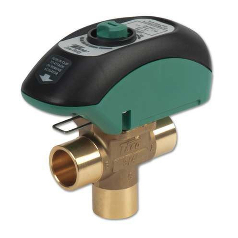
Taco Comfort Solutions 5120 Series User manual

Instruction Sheet
High Flo 5120 Series Lead Free (≤ .25% Pb) Mixing Valve
102-491
SUPERSEDES: N w EFFECTIVE: August 1, 2013
Plant I.D. 001-4205
WARNING: Water temperatures above 120°F can cause serious injury. Mixing valve temperature setting should be
done by a licensed professional per local code requirements. Use an accurate water thermometer to verify the final
water temperature. The thermostatic strip provided must not be used for final water temperature verification.
WARNING: The High Flow 120 Series must not be installed on steam systems (water systems only).
WARNING: High Flow 120 Series mixing valves are certified to ASSE 1017 and not designed to compensate for
system pressure fluctuations beyond the valves variation rating and should not be used where more sophisticated
pressure compensating temperature controls are required.
CAUTION: Do not use excess thread sealant (in liquid, tape or other form) as this may cause a valve failure.
CAUTION: Valve must not be subjected to heat during the installation, this may damage the valve’s internal
components.
GENERAL:
The Taco High Flow 120 Series is listed for ASSE 1017 applications.
• All installations should b carri d out by a Lic ns d Prof ssional. Failur to comply with all asp cts of th s instructions
may r sult in unsaf p rformanc . All installations must comply with r l vant Stat and Local cod s or authoriti s.
• Ensur compatibility of valv installation, .g. t mp ratur of hot wat r, inl t pr ssur , flow rat s, tc. - r f r to product
sp cifications. If th sit conditions ar outsid of th sp cifications for th valv , th sit conditions must b corr ct d or
a valv that m ts th conditions must b s l ct d.
• Install in accordanc with markings on valv body, i. . hot wat r inl t - mark d “H”, cold wat r inl t - mark d “C” and mix d
outl t - mark d with dir ctional arrow.
• Valv may b install d in any position.
• Any inconsist ncy b tw n th s instructions and any sp cific instructions, bylaws or cod s issu d by local authoriti s
must b r f rr d back to Taco, Inc. prior to any installation taking plac .
• During startup nsur that th valv is s t to th d sir d t mp ratur (valv pr s t at 115-120°F (46.1-48.9°C) with 150°F
(66°C) hot wat r inl t t mp ratur ). If th valv t mp ratur n ds to b adjust d pl as r f r to th instructions b low (SET-
TING VALVE OUTLET TEMPERATURE).
NOTE: If the water supply is of poor quality a filter or strainer should be fitted at the system inlet so that both the water
heater and the mixing valve are protected from dirt and debris.
FITTING VALVE TO PIPING SYSTEM:
• Flush all piping thoroughly b for installing th valv (using wat r only). Not flushing th syst m prop rly is th most com-
mon caus of improp r valv p rformanc .
• Union valv s com compl t with union typ conn ctions for as of installation and s rvic .
• Valv must b r mov d from th piping prior to sold ring th nd conn ctions. It is r comm nd d to us a spac r pi c
whil sold ring.
SETTING VALVE OUTLET TEMPERATURE:
Th Taco High Flow 5120 S ri s Mixing Valv is suppli d factory s t at 115-120°F with 150°F hot wat r inl t t mp ratur . It
may n d to b alt r d d p nding on op rating r quir m nts.
1. R mov th knob scr w and th n r mov th adjusting knob, r plac it in a n w position, to th l ft sid of
th lock ring to d cr as t mp ratur or to th right sid to incr as t mp ratur . This will allow th knob
to rotat fr ly. Th r should b no n d to r mov th whit locking ring. (S Figur 1)
2. To adjust th mix d outl t t mp ratur of th valv , simply turn th knob – clockwis to r duc th t mp r-
atur , count r clockwis to incr as th t mp ratur – until th d sir d s t point is r ach d. (S Figur 2)
3. R mov and r position th adjusting knob so that th indication mark on th adjusting knob lin s up with
th indication mark on th valv body, making sur th splin of th st m also aligns with th splin of th
cap, and push down into plac (this will lock th adjusting knob into position so it cannot b rotat d) and
th n r plac th s curing scr w. (S Figur 3)
4. Using an accurat th rmom t r, t st th mix d wat r t mp ratur at th n ar st outl t b ing suppli d by
th valv . Th t st outl t should not b a show r with its own t mp ratur limiting control valv . This should
b op n d to allow a minimum flow rat of 2.5 gpm (9.5 L/min). Allow th wat r to run for at l ast on minut
to nsur th mix d wat r t mp ratur has s ttl d. (S Figur 4)
5. A t mp ratur strip is provid d with ach mixing valv and can b us d as a r f r nc to s t th t mp ra-
tur , how v r a mor accurat d vic should b us d to nsur a corr ct t mp ratur s tting.

50
45
40
35
30
25
20
15
10
5
0
0510 15 20 25 30
GPM
PSI
FLOW CURVE:
HOT
COLD
COLD
MIX
COLD WATER LOOP
FLOW REGULATOR
12" RECOMMENDED
HOT
WATER HEATER
TYPICAL ASSE 1017 INSTALLATION:
FIGURE 2:FIGURE 1:
FIGURE 4:FIGURE 3:
Adjusting Knob
Indication Mark
Valv Body
Indication Mark
Turn
clockwis
to d cr as th
tmp ratur .
Turn
count rclockwis
to incr as th
tmp ratur .

TROUBLESHOOTING:
This troubl shooting tabl is int nd d as a h lpful guid and is not all inclusiv . Th r could b oth r caus s and solu-
tions for a non-functioning product.
SPECIFICATIONS:
Hot Wat r Inl t T mp ratur : 120-180°F (60-90°C) Factory Pr s t: 115-120°F (41-46°C)
Cold Wat r Inl t T mp ratur : 39-80°F (4-27°C) Outl t Wat r T mp ratur Rang : 85-176°F (29-80°C)
Maximum D sign Pr ssur : 230 psi (13.8 Bar) Minimum T mp ratur Diff r ntial
(b tw n hot supply and outl t): 27°F (15°C)
Minimum Flow Rat : 2.5 GPM (9.5 L/min) Allowabl Supply Pr ssur Variation: ±20%1
Maximum Flow Rat : 27.2 GPM (100 L/min) Accuracy of Outl t T mp ratur : ±5°F (±2°C)2
Notes:
1. Maximum allowabl variation in ith r supply pr ssur in ord r to control th outl t t mp ratur to within ±5°F.
Warning: Pressure variations outside of this range may cause changes in the outlet temperature.
2. P r ASSE 1017 t sting proc ss.
MAINTENANCE:
Th Taco High Flow 5120 S ri s Mixing Valv is an ASSE 1017 SAFETY VALVE. It do s not r quir routin maint nanc
but should b ch ck d annually to b sur it is functioning prop rly. For installations with poor wat r quality it may b
n c ssary to insp ct th mixing valv mor fr qu ntly. R plac m nt l m nt ass mbli s ar availabl .
FAULT / SYMPTOM CAUSE POSSIBLE SOLUTION
1. Th d sir d mix d wat r t mp ratur
cannot b obtain d or valv is diffi-
cult to s t.
• Inl t t mp ratur s ar not within sp c-
ification limits.
• Hot and cold suppli s ar r v rs d.
• Strain rs ar block d.
• Ensur inl t t mp ratur s ar within
th sp cifi d limits for th valv .
• R fit th valv with Hot/Cold suppli s
fitt d to th corr ct conn ctions.
• Cl an strain rs.
2. Mix t mp ratur unstabl or chang-
ing ov r tim .
• Strain rs ar block d.
• Fluctuating supply pr ssur s.
• Cl an strain rs.
• Install pr ssur r gulating valv s on
both hot and cold suppli s.
3. Eith r full hot or full cold wat r flow-
ing from outl t fixtur .
• Valv is incorr ctly s t.
• Hot and cold suppli s ar r v rs d.
• Hot/Cold wat r has migrat d to oth r
inl t.
• R f r also to point 1.
• Adjust mix t mp ratur as r quir d.
• R fit th valv with Hot/Cold suppli s
fitt d to th corr ct conn ctions.
• V rify th ch ck valv is not foul d.
Cl an if n c ssary.
4. No flow from th valv outl t.
• Hot or cold wat r supply failur .
• Strain rs ar block d.
• R stor inl t suppli s and ch ck mix
t mp ratur .
• Cl an strain rs.
5. Flow rat r duc d or fluctuating. • Strain rs ar block d.
• Fluctuating supply pr ssur s.
• Cl an strain rs.
• Install pr ssur r gulating valv s.
6. Mix d wat r t mp ratur do s not
chang wh n t mp ratur adjust r is
alt r d.
• Hot and cold suppli s ar r v rs d. • R fit th valv with Hot/Cold suppli s
fitt d to th corr ct conn ctions.
7. Hot wat r flows into th cold wat r
syst m or vic v rsa.
• Ch ck valv s foul d. • Cl an ch ck valv s, nsuring d bris is
r mov d.
8. Valv is noisy.
• Exc ssiv wat r v locity.
• Valv siz d incorr ctly.
• R duc wat r v locity (b st achi v d
by fitting a pr ssur r gulating valv ).
• Ch ck valv sp cifications and nsur
th appropriat valv is us d for
r quir d flow.

Taco, Inc. will r pair or r plac without charg
(at th company’s option) any product or part
which is prov n d f ctiv und r normal us
within on (1) y ar from th dat of start-up or
on (1) y ar and six (6) months from dat of
shipm nt (which v r occurs first).
In ord r to obtain s rvic und r this warranty, it
is th r sponsibility of th purchas r to prompt-
ly notify th local Taco stocking distributor or
Taco in writing and promptly d liv r th subj ct
product or part, d liv ry pr paid, to th stocking
distributor. For assistanc on warranty r turns,
th purchas r may ith r contact th local Taco
stocking distributor or Taco. If th subj ct prod-
uct or part contains no d f ct as cov r d in this
warranty, th purchas r will b bill d for parts
and labor charg s in ff ct at tim of factory
xamination and r pair.
Any Taco product or part not install d or op rat-
d in conformity with Taco instructions or which
has b n subj ct to misus , misapplication, th
addition of p trol um-bas d fluids or c rtain
ch mical additiv s to th syst ms, or oth r
abus , will not b cov r d by this warranty.
If in doubt as to wh th r a particular substanc
is suitabl for us with a Taco product or part, or
for any application r strictions, consult th
applicabl Taco instruction sh ts or contact
Taco at (401-942-8000).
Taco r s rv s th right to provid r plac m nt
products and parts which ar substantially simi-
lar in d sign and functionally quival nt to th
d f ctiv product or part. Taco r s rv s th right
to mak chang s in d tails of d sign, construc-
tion, or arrang m nt of mat rials of its products
without notification.
TACO OFFERS THIS WARRANTY IN LIEU OF
ALL OTHER EXPRESS WARRANTIES. ANY
WARRANTY IMPLIED BY LAW INCLUDING
WARRANTIES OF MERCHANTABILITY OR
FITNESS IS IN EFFECT ONLY FOR THE DURA-
TION OF THE EXPRESS WARRANTY SET
FORTH IN THE FIRST PARAGRAPH ABOVE.
THE ABOVE WARRANTIES ARE IN LIEU OF
ALL OTHER WARRANTIES, EXPRESS OR
STATUTORY, OR ANY OTHER WARRANTY
OBLIGATION ON THE PART OF TACO.
TACO WILL NOT BE LIABLE FOR ANY SPE-
CIAL, INCIDENTAL, INDIRECT OR CONSE-
QUENTIAL DAMAGES RESULTING FROM THE
USE OF ITS PRODUCTS OR ANY INCIDENTAL
COSTS OF REMOVING OR REPLACING
DEFECTIVE PRODUCTS.
This warranty giv s th purchas r sp cific
rights, and th purchas r may hav oth r rights
which vary from stat to stat . Som stat s do
not allow limitations on how long an impli d
warranty lasts or on th xclusion of incid ntal
or cons qu ntial damag s, so th s limitations
or xclusions may not apply to you.
LIMITED WARRANTY STATEMENT
TACO, INC., 1160 Cranston Str t, Cranston, RI 02920 T l phon : (401) 942-8000 FAX: (401) 942-2360.
TACO (Canada), Ltd., 8450 Lawson Road, Unit #3, Milton, Ontario L9T 0J8. T l phon : 905/564-9422. FAX: 905/564-9436.
Visit our web site at: http://www.taco-hvac.com
Print d in USA
Copyright 2013
TACO, Inc.
O-RING/PISTON SUB-ASSEMBLY REPLACEMENT:
1. Isolat th valv from th wat r supply.
2. Unscr w th union nuts and r mov th valv body from th syst m. Removing the valve from the piping system
is not required but may make replacement easier.
3. R mov th gr n cap from th valv .
4. S cur th valv body (using th flats on th body) and unscr w th brass cap to r mov th int rnals of th valv .
5. R mov th piston ass mbly out of th top of th valv . If n c ssary, push th piston ass mbly from th outl t port
of th valv .
6. Using a cl an cloth g ntly wip out th valv body paying particular att ntion to th o-ring half way down th insid
of th valv body.
7. R mov th o-ring from th cap. Lightly gr as th n w cap o-ring and r -gr as th o-ring half way down th insid
of th valv with th gr as pack t provid d.
8. Ass mbl in th r v rs ord r.
9. Wh n r -fitting th brass cap do not ov r tight n, as this is an o-ring s al.
10. If r mov d, r install th valv into th piping syst m and s t th outl t mix t mp ratur as indicat d abov in
SETTING THE OUTLET TEMPERATURE.
Table of contents
Other Taco Comfort Solutions Control Unit manuals
Popular Control Unit manuals by other brands

Beta LaserMike
Beta LaserMike LASERSPEED 8000 Instruction handbook

SAFEMATIC
SAFEMATIC ST-1440 manual

VarioTherm
VarioTherm Pumped Manifold manual

Gatekeeper Systems
Gatekeeper Systems SmartKey2 user manual

harvst
harvst WaterMate Setup and installation guide

Siemens
Siemens REMBOX2-MP installation instructions