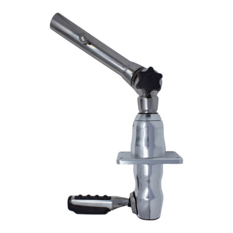
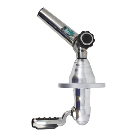
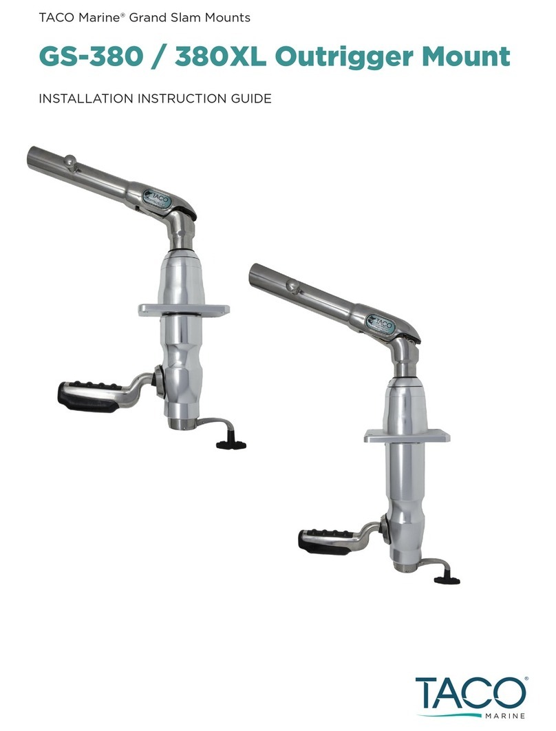
Taco Marine GS-850 Datasheet

GS-850 & GS-950 Mounts
INSTALLATION INSTRUCTION GUIDE
TACO Marine® Grand Slam Mounts
®

2 / GS-850 & GS-950 MOUNTS
Grand Slam 850 mount
(for both the GS-850 and GS-950)
• Always use good quality stainless steel
hardware when mounting the base.
• Please do not attempt to weld the base
to anything.
• It is also important that your Canvas
T-Top, Arch or Hardtop, be suitably
constructed to provide a strong
mounting surface area.
Kit Contents
GS-850/GS-950
Handy Tips
1•SAFETY GLASSES
•DRILL & SCREW GUN
•MASKING TAPE & PENCIL
•1/4" DRILL BIT
•THREE 1/4-20 FLAT HEAD SCREWS
(LENGTH= (THICKNESS OF TOP) + 7/8”)
•THREE 1/4-20 LOCKING NUTS
•MARINE-GRADE SEALANT
•MARINE-GRADE GREASE / ANTI-SEIZE
•3A FUSE IN THE MAIN +12 VDC POWER FEED
•GS-950 ONLY - 3A FUSE FOR LIGHT
•FLATHEAD SCREWDRIVER
•18-GAUGE WIRE FOR GS-850 & GS-950
•TWO-POSITION SWITCH (UP/DOWN) FOR GS-
850 & GS-950
•THREE-POSITION SWITCH (OFF/ON/ON) FOR
THE GS-950 ONLY
Required,
but not included
®
Tube, light and 10" lead for 12-
volt DC power supply for light
function (GS-950 only)
1
Drill template
1
Vinyl tubing spacers
3
10" lead for 12-volt DC power
supply for lift and descent
(for both the GS-850 and GS-950)
1

GS-850 & GS-950 MOUNTS / 3
GS-850/GS-950
• The three (3) vinyl spacers will help prevent
any hardtop compression. When installing
through a hardtop, make sure the top is
foam or core filled. It is recommended to
use included spacers to fit inside where the
mounting bolts pass through to ensure that
when the bolts are tightened the top is not
compressed.
• Position the mount with the antenna or light
attached so that it will not interfere with
other hardware on the top.
• Route electrical cables to boat’s control
panel and attach wires per manufacturer’s
recommendations.
• Before installing VHF Antenna or LED Light
Tube, apply a thin layer of marine grease or
anti-sieze to the threaded shaft.
Thank you for purchasing the TACO Marine Grand Slam 850 VHF Antenna Mount or Grand
Slam 950 Anchor & Stern Light! As a family-owned and operated business since 1959, we
take pride in oering the highest-quality, innovative products with excellent customer
service. We stand behind our products 100 percent. If you have any questions about this
mount or installation, please contact us by visiting tacomarine.com/contactus.
1. Use the drill template to mark and drill with a 1/4" bit the three bolt holes.
2. If your top requires spacers, trim the included vinyl spacers to the depth of your
hardtop thickness. Insert the vinyl spacers into each bolt hole.
3. Place a bead of marine-grade sealant on the underside of the mounting plate. This
helps prevent water intrusion.
4. Securely bolt the base to the mounting surface. Be careful not to deform the top.
5. Connect wire according to Figures 1, 2 and 3 on page 6.
6. Use a 3A fuse in the main +12 VDC power feed.
7. Ensure the Black wire has a good connection to battery ground.
8. Operate the unit in both directions. The unit will automatically stop at full-up and
lay-down positions.
9. Connect wire antenna according to manufacturer's instructions.
GS-850 MOUNT INSTALLATION
FOR ANTENNA

4 / GS-850 & GS-950 MOUNTS
1. Use the drill template to mark and drill with a 1/4" bit the three bolt holes.
2. If your top requires spacers, trim the included vinyl spacers to the depth of your
hardtop thickness. Insert the vinyl spacers into each bolt hole.
3. Place a bead of marine-grade sealant on the underside of the mounting plate. This
helps prevent water intrusion.
4. Securely bolt the base to the mounting surface. Be careful not to deform the top.
5. Connect wire according to Figures 1, 2 and 3 on page 6.
6. Use a 3A fuse in the main +12 VDC power feed (not included).
7. Use a 3A fuse for the light (not included).
8. Ensure the Black wire has a good connection to battery ground.
9. Operate the unit in both directions. The unit will automatically stop at full-up and lay-
down positions.
10. Screw down the bottom of the light tube assembly to the mount.
NOTE: Before installing the LED Light Tube, apply a thin layer of marine grease or
anti-sieze to the threaded shaft.
NOTE: For instructions and to replace the Grand Slam 950 Anchor & Stern
Light, purchase a replacement [F38-9000BLY] at tacomarine.com.
GS-950 MOUNT INSTALLATION
FOR ANCHOR & STERN LIGHT

GS-850 & GS-950 MOUNTS / 5
LIGHT
The light assembly is composed of two parts – one (1) Lamp
Assembly and one (1) Stanchion.
EMERGENCY RELEASE OPERATION
Using a standard flathead screwdriver, remove the set screw (A) located on the side
of the GS-850 and GS-950 base while holding the Antenna or Anchor & Stern Light
shaft, being careful not to let the shaft fall. Once the screw is removed, gently lift up
on the shaft and reposition the Antenna or Anchor & Stern Light. Once repositioning is
complete, gently push back in the shaft until the screw holes are aligned and re-screw
in the screw with the screwdriver, making sure not to over tighten and strip the threads.
Repeat this process whenever manual override is necessary.
1. Thread the LED light tube to the GS-850 mounting base.
Note: Apply a thin layer of marine-grade grease or anti-seize to the threads before
installing.
2. Noting the sticker that reads “TO BOW” on the light, position the light properly for
anchor/stern designation.
3. Attach your 18-Gauge, 3-wire cable coming from the helm to the 18-Gauge, 3-wire lead
out of the GS-950 stanchion/tube assembly (refer to figure 4 on page 8).
4. Connect your chosen switch (not included) per manufacturer’s recommendations.
5. Mount the switch to your chosen location at the helm.
(A) Set Screw

6 / GS-850 & GS-950 MOUNTS
When boating with the Grand Slam 850 or Grand Slam 950, easily adjust the top-moun-
ted VHF Antennas or Anchor & Stern Light with the simple push of a button. Once
either accessory is mounted to the top and wired into the control panel, lift or des-
cend the accessories by pressing the up or down buttons. When either accessory
has reached its full upright or down position, the motor will stop automatically.
How to use
How to clean
Mild dish washing liquid, specialty marine cleaners:
Sea Safe Boat Wash, Boat Wash Concentrate
and Super Suds.
Safe marine lubricants:
CRC Corrosion Inhibitor, Corrosion Block
and Get Some Extreme.
Bleach (Clorox, etc.) and mild abrasive cleaners:
Ajax, Comet, Soft Scrub, Rubbing Compounds, etc.
Strong cleaners:
409, Engine Degreasers, etc.
Acids of any type:
Such as Muriatic, naval jelly or aluminum acid.
Always use a mild, non-abrasive soap and lots of fresh water. Thoroughly wash the
aluminum with a soft towel or sponge utilizing lots of soap and water to remove
all dried salt crystals and other contaminants. Rinse completely with direct water
pressure.
Safe Cleaners Harmful Cleaners

GS-850 & GS-950 MOUNTS / 7
WIRING DIAGRAMS
16
25
34
+12 VDC (Red) Lower Limit (White)
Upper Limit (Brown)
Motor - (Black) Motor + (Green))
Blank
Motor Connection
Lower Limit (White)
Upper Limit (Brown)
Motor - (Black) Motor + (Green))
LED GND LED +
LED +
LED GND
GRD
GRD
Switch Connection
2.5 amp
fuse
WIRING SWITCH SCHEMATIC (FIGURE 1)
16
25
34
+12 VDC (Red) Lower Limit (White)
Upper Limit (Brown)
Motor - (Black) Motor + (Green))
Blank
Motor Connection
Lower Limit (White)
Upper Limit (Brown)
Motor - (Black) Motor + (Green))
LED GND LED +
LED +
LED GND
GRD
GRD
Switch Connection
2.5 amp
fuse
MOTOR CONNECTION (FIGURE 2)
SWITCH CONNECTION (FIGURE 3)
16
25
34
+12 VDC (Red) Lower Limit (White)
Upper Limit (Brown)
Motor - (Black) Motor + (Green))
Blank
Motor Connection
Lower Limit (White)
Upper Limit (Brown)
Motor - (Black) Motor + (Green))
LED GND LED +
LED +
LED GND
GRD
GRD
Switch Connection
2.5 amp
fuse

8 / GS-850 & GS-950 MOUNTS
Bow
Stern
Port
Starboard
Blinds are
to the rear
of centerline
C
L
Black
Ground
Red
Stern
Light
Red
Bow
Light
Red Bow
Light
Red Stern
Light
Black
Ground
ANCHOR AND STERN LIGHT (FIGURE 4)
WIRING DIAGRAMS

GS-850 & GS-950 MOUNTS / 9
6.54
1.00
.25
4.25 1.73
4.60
3.20
6.93
DOWN POSITION
UP POSITION
6.54
.25
39.25
4.25 1.73
41.58
DOWN POSITION
UP POSITION
PRODUCT DIMENSIONS
6.54
1.00
.25
4.25 1.73
4.60
3.20
6.93
DOWN POSITION
UP POSITION
DOWN POSITION
UP POSITION
6.54
.25
39.25
4.25 1.73
41.58
DOWN POSITION
UP POSITION
DOWN POSITION
6.54
.25
39.25
4.25 1.73
41.58
DOWN POSITION
UP POSITION
UP POSITION

Please print at 100 percent for accurate sizing. Slight scaling may still
occur. Therefore, before drilling, it is recommended that all template
dimensions be measured for accuracy.
10 / GS-850 & GS-950 MOUNTS
GS-850/GS-950
Drill Template

GS-850 & GS-950 MOUNTS / 11
Need Support?
1.800.653.8568
support@tacomarine.com
tacomarine.com
50 NE 179th ST
Miami, FL. 33162
@tacomarine
@taco_marine
TACO Marine®
Contact Us
We’re here to help.

®
INSTRUCT-GS-850/950
Other manuals for GS-850
1
This manual suits for next models
1
Table of contents
Other Taco Marine Boating Equipment manuals
Popular Boating Equipment manuals by other brands

Seakeeper
Seakeeper 7000 GYRO Technical bulletin

Classic Accessories
Classic Accessories Stellex T-Top Instructions & Care

SureShade
SureShade MTF Installation guides

Lewmar
Lewmar FLUSH 2G Flush Hatch Fitting & Adjustment Instructions

DockStar
DockStar Smart Thruster Operation manual

Seiwa
Seiwa SW RP07 user guide