Taco GT Horizontal 302-054 User manual

SUPERSEDES: New EFFECTIVE: March 1, 2009
Plant ID No. 001-3930
GT Horizontal
Split Casing Pumps
Operations and Maintenance Manual
302-054
SAFETY REQUIREMENTS
These operating instructions must be complied with during instal-
lation, operation and maintenance, and must be read by the
operator before commencement of any work. Only fully qualified
personnel may carry out work on the pump set. Non-compliance
with these instructions may lead to damage to the equipment,
serious injury or hazard to the environment.
A: GENERAL
Taco GT pumps are single stage double suction axially split
pumps supplied either bare shaft or complete with an electric
motor. Details of the pump type and model, serial number and
operating data are indicated on the pump nameplate.
The pump must be installed and operated in full compliance with
these instructions. The pump may not be operated outside the lim-
its specified on the nameplate and within this manual. The pump
should only be operated by skilled trained personnel. The manu-
facturer will not accept liability if these instructions are not fol-
lowed. This manual does not take into account any specific local
regulations or bylaws that may be applicable, and it is the respon-
sibility of the installer to ensure compliance with such regulations.
A1: Application
Taco GT pumps are suitable for continuous pumping of clean
water and liquids with properties similar to water, with fine solids
content not exceeding 200 ppm.
A2: Area of Operation
May be installed within a building or externally. Wherever
installed, protect the pump from frost, snow and flooding. Care
must be taken to ensure that cold weather will not cause the
pump or pipes to freeze, and installers may wish to consider lag-
ging or trace heating.
A3: Spare Parts
Spare parts are available from Taco distributors which can be
located at www.taco-hvac.com. Please quote the pump model
and serial number for all spares enquiries.
The pump user is strongly recommended to carry replacement
spares for parts which are wearing items:
• Mechanical seal or gland packing
• Casing wear ring
• Shaft sleeve
• Casing gasket
• Gland plate gasket
Only genuine Taco spare parts should be fitted. Use of other
parts will invalidate the manufacturer’s warranty and liability for
consequential damage.
A4: Transport
The pumpset must remain horizontal during transport and lifting.
Only use certified lifting equipment suitably rated for the weights
to be lifted.
When hoisting the bareshaft pump only, secure a sling of suitable
load capacity around the suction flange and bearing housing as
indicated (see Figure 1). For new installations, keep the pump on
its original pallet while moving around site or on transport. If the
original pallet is not available, the pump should be securely bolted
to a pallet of generous size to ensure stability.
Lifting the complete pumpset (pump, motor and bedplate) may
be carried out using a forklift or with a set of lifting chains secured
to the lifting points provided on the bedplate (see Figure 2).
CAUTION: Read these instructions before
putting the pump into service.
CAUTION: Installation and operation should
be carried out by qualified personnel only.
CAUTION: Danger of electrocution. Electric
supply must be isolated before working on
the pump set.
CAUTION: Electrical work should only be
carried out by qualified personnel.
Figure 1: Attaching a Sling to the Pumpset

A5: Storage
If not to be used immediately, the pumpset should be stored in a
dry, warm and vibration-free environment. For extended periods
of storage, pump and motor shaft should occasionally be rotated
one full turn. Do not remove flange covers until the pump is ready
to be connected to its pipework.
A6: Foundation
The foundation should be sufficiently substantial to reduce vibra-
tions and rigid enough to avoid any twisting or misalignment.
(See Figure 3.)
The foundation should be poured without interruptions to within 1⁄2
to 11⁄2inches of the finished height. The top surface of the foun-
dation should be well scored and grooved before the concrete
sets. This provides a bonding surface for the grout. Foundation
bolts should be set in concrete. Allow enough bolt length for
grout, shims, lower baseplate flange, nuts and washers. The foun-
dation should be allowed to cure for several days before the base-
plate is shimmed and grouted.
A7: Baseplate Setting
Use blocks and shims under base for support at foundation bolts
and midway between bolts to position base approximately 1 inch
above the concrete foundation with the studs extending through
holes in the baseplate.
(See Figure 4.)
By adding or removing shims under the base, level the pump
shaft and flanges. The baseplate does not have to be level.
Draw foundation bolt nuts tight against baseplate and observe
pump and motor shafts or coupling hubs for alignment.
Check to make sure the piping can be aligned to the pump
flanges without placing pipe strain on either flange.
Grout baseplate in completely and allow grout to dry thoroughly
before attaching piping to pump (24 hours is sufficient time with
approved grouting procedure).
A8: Grouting Procedure
Grout compensates for uneven foundation, distributes weight of
unit and prevents shifting (see Figure 4). After setting and level-
ling unit, use an approved, non-shrinking grout as follows:
(a) Build strong form around foundation to contain grout.
(b) Soak top of concrete foundation thoroughly, then remove
surface water.
(c) Baseplate should be completely filled with grout and, if
necessary, drill vent holes to remove trapped air.
(d) After the grout has thoroughly hardened, check the
foundation bolts and tighten if necessary.
(e) Check the alignment after the foundation bolts are
tightened.
(f) Approximately 14 days after the grout has been poured or
when the grout has thoroughly dried, apply an oil base
paint to the exposed edges of the grout to prevent air and
moisture from coming in contact with the grout.
A9: Coupling Alignment
Although the coupling will have been aligned during manufacture,
it is important that the cou-
pling alignment is checked
and, if necessary, adjusted
after installation. Small deflec-
tions of the bedplate during
transport and installation can
affect the alignment. A mis-
aligned coupling can cause
vibration and reduced bear-
ing life for the pump and
motor.
2
CAUTION: When using a forklift, particular
care should be taken to properly balance the
load. The electric motor may be significantly
heavier or lighter than the pump. If possible,
use the original pallet or skid provided.
MAX 90°
Figure 2: Lifting the Complete Pumpset
STRAIGHT EDGE
Figure 5a
FOUNDATION
BOLT
PIPE
SLEEVE
CONCRETE
WASHER
Figure 3
Figure 4

3
Use a straight edge and
gauge to check the parallel
alignment and the angular
alignment.
Adjustment is usually made
by moving the motor, and
adding or subtracting shims
from under the motor feet.
(See Figures 5a and 5b.)
A10: Pipe Connections
Pipes must be independently supported, and arranged in such a
way that expansion or contraction along the length of the pipe does
not impose strain on the pump flanges. Never use the pump itself
to support the pipes. Locate pipe supports close to the pump.
Never force the pipes into place to align with the pump flanges, as
this will impose unacceptable loads on the pump. Where neces-
sary, flexible jointed pipework should be fitted to accommodate
small movement of the pipe and eliminate strain on the pump.
It is usual practice to fit pipes of one or two sizes larger than the
bore of the pump’s suction and discharge. For short pipe runs, it
may be economical to fit pipes of the same diameter as the pump
flanges. Do not fit pipes of a smaller bore than the pump flange size.
Most systems require the installation of suction and discharge
valves, and a non-return valve on the discharge pipeline. We would
recommend fitting such valves for ease of maintenance. If the
flowrate is to be regulated or initially set with the discharge valve,
fit a gate valve in preference to a wafer type discharge valve.
Before final connection of the pump on a new system, thoroughly
clean and flush all suction pipes and tanks to eliminate weld
debris and scale, which can become dislodged and block the
suction of the pump. A temporary strainer can be fitted to the
suction line to prevent debris from entering the pump.
A11: Electrical Connection
Where the pump is to be driven by an electric motor, observe the
instructions provided by the electric motor manufacturer.
Electrical installation should only be carried out by a skilled elec-
trician. The installation should be grounded at the motor, pipes,
support frame and pump as appropriate.
A12: Vibration Isolation
Pumps installed in some buildings may require isolation from the
floor and pipes using anti-vibration mounts and flexible pipe con-
nectors.
B: OPERATION
When correctly installed and operated, this Taco pump will give
many years of trouble-free service. In operation, the pump should
be free from vibration and run smoothly. Any changes to smooth-
ness of operation should be investigated immediately. The pump
should be visually checked periodically.
B1: Priming the Pump
Pumps operating on flooded suction conditions (where the liquid
source is higher than the pump) are easily primed by opening the
suction valve, releasing air vent on the pump discharge, and
allowing the pump casing to fill with liquid. (See Figure 6.)
For pumps operating on a suction lift, the usual practice is to fit a
foot valve to the suction pipe. This foot valve retains liquid within
the suction pipe and pump casing when the pump is idle.
B2: Starting the Pump
Before the pump is started for the first time, it is important to
check the following points:
• Check that the pump rotates freely by hand.
• Open the suction valve fully and evacuate all the air
inside the pump casing to prime the pump.
• Close the discharge fully for the first start after
installation or service.
• Momentarily start and stop the electric motor or engine
driver to check that the rotation is correct.
• The pump may now be run. On starting, observe the
discharge pressure.
• Slowly open the discharge valve. The pressure will
gradually fall as the flowrate through the pump increases.
• Open the discharge valve only until the required pressure
is indicated on the pressure gauge.
B3: Over-Pumping
When pipework system losses are estimated, an extra allowance
in head is often made for pipe deterioration, or the pump is over-
sized to allow for future expansion. In these circumstances, it is
likely that the pump will operate at a higher flowrate than intended,
which may result in excessive loads on the pump bearings and
driver overload. The operator should limit the flow by adjustment
of the discharge valve, referring to the discharge pressure gauge
to obtain the design conditions. For pumps driven by electric
motor, the operator should verify that the motor nameplate current
is not being exceeded.
B4: Minimum Flowrate
Taco GT pumps should not be continually operated at a flowrate
below 30% of the peak efficiency flowrate unless otherwise
specifically agreed by the manufacturer. If the system is such that
zero flow or less than 30% of peak efficiency flow will occur, a
return line must be fitted.
CAUTION: Isolate the electrical supply
before commencing work on the pump.
Figure 5b
AIR VENT
Figure 6: Air Vent Location

4
B5: Thermal Shock
Taco GT pumps are not designed to withstand rapid changes in
temperature. Where a pump is handling hot liquids, the liquid
should be introduced slowly allowing the pump to gradually
increase in temperature.
B6: Thermal Hazards
Pumps handling hot liquid in excess of 154°F present a hazard to
personnel if the hot surface of the pump casing or associated
pipework is touched. The installer is responsible for warnings and
means of protection.
B7: Materials Compatibility
The materials of construction of this pump have been selected by
agreement between the manufacturer and the buyer, to be com-
patible with the pumped liquid as specified. The installer is
responsible for ensuring that the liquid actually handled on site is
as specified. Should there be any doubt, the installer is to seek
advice before proceeding.
B8: Controlling Solids
Where solids may be present, a strainer may be fitted to the
pump suction line to prevent entry into the pump impeller, pre-
venting possible damage to the impeller. A regular schedule
should be established to check and clean the strainer. A blocked
strainer will cause the pump to cavitate resulting in damage to the
impeller.
B9: Dry Running
The pump must never be allowed to run dry. Possible seizure of
the internal close clearances, and failure of the mechanical seal
may result. The operator should regularly check that the pump
suction source is adequate. In some installations, it may be pru-
dent to fit a level device or other means of automatic protection
to prevent the pump from dry running.
B10: Automatic Operation
Pumps operating on an automatic control system must not be
allowed to run at zero flow or flow below 30% of the peak effi-
ciency flowrate. Interlocks should be fitted appropriate to the
system. The pump should not be started more than 10 times per
hour, as damage to the shaft coupling and driver may result.
Installation of a pressure tank or timers on the electrical control
should be considered as required to reduce the frequency of
starts.
B11: Protection from Freezing
Where the pumpset may be exposed to cold weather, ensure that
the pump and associated pipework is lagged or trace heated to
prevent frost damage.
C: MAINTENANCE
C1: Electrical Supply Isolation
For pumps driven by electric motor, always isolate the electrical
power supply before working on the pump. Affix a notice on the
electrical isolator to inform others that work is being carried out
on the installation. If possible lock closed the supply isolator.
C2: Lubrication
The pump bearings are provided with grease fittings. Apply a high
quality bearing grease (Shell Alvania or equal) every 2000 hours,
or every six months, whichever comes first. Grease containing
dust and particles will quickly destroy the bearings. Only use
fresh grease from a sealed grease gun.
C3: Mechanical Seal
The mechanical seal is a wearing item. Life of a seal depends on
the erosive properties of the pumped liquid, and the temperature
and pressure of operation. The seal is self-adjusting, and requires
no periodic maintenance.
C4: Strainer
If a strainer is fitted to the suction pipe before the pump, period-
ically check and clean the strainer element. A blocked or leaking
strainer will cause cavitation damage to the impeller.
C5: Free Rotation
The pump should rotate freely by hand. Having isolated the
power supply, remove one of the guards and rotate the shaft by
hand to check freedom of rotation. Replace all guards prior to
operating the pump.
C6: Flooding
If the pump is accidentally subjected to flooding, on no account
operate the pump until it is thoroughly dry and checked. If water
has entered the pump’s bearing housing, it is likely that the bear-
ings will need to be cleaned or replaced. For pumps driven by an
electric motor, check that the motor fan is cleared of debris and
is free to rotate.
Inspect the pump shaft for debris.
D: DISASSEMBLY
D1: Special Tools
No special tools are required for disassembly of the pump set. In
preparation for disassembly, the pump should be allowed to cool
to ambient temperature before commencing any work. Close the
suction and discharge valves and drain the pump of liquid by
releasing the casing drain plug. If the pump is driven by an elec-
tric motor, ensure the power supply is isolated.
D2: Removing the Casing Top Half
Access to the pump internals is provided by a removable casing
top half. Before proceeding with removal, ensure that gasket
material of the correct thickness is available, as the gasket should
be replaced.
1) With the coupling guard removed, disconnect the drive cou-
pling between pump and driver.
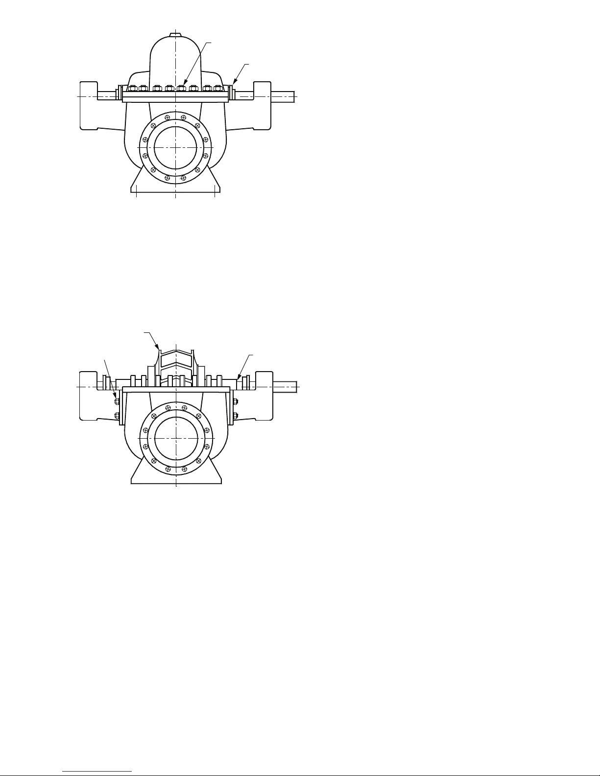
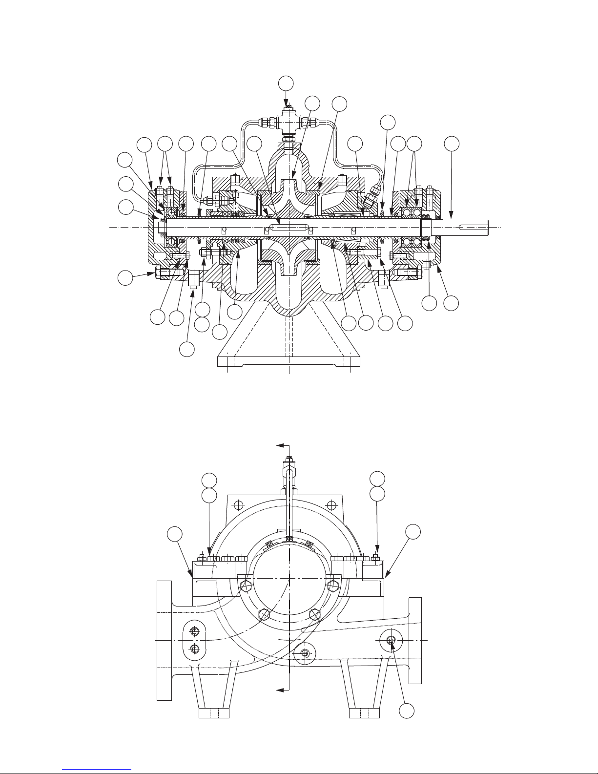
2) Withdraw the two glands (for packed gland pumps) or
mechanical seal glandplates, if fitted, by removal of their
retaining nuts. Slide the glands or glandplates along the shaft
toward each bearing. (See Figure 7.)
3) Remove all the nuts on the casing split flange.
4) Using the jacking bolts provided, the casing top half may now
be separated and raised by 1-2 mm.
5) Using suitable lifting tackle, the top half casing may now be
lifted away. The pump internals may now be inspected.

5
D3: Removing the Rotating Assembly
The complete rotating assembly, comprising the impeller, shaft,
shaft sleeves and bearings may be lifted out as a single unit.
Release the bearing bracket bolts, and use a soft sling around the
exposed parts of the shaft to lift the rotating assembly clear.
(See Figure 8.)
D4: Removing the Impeller
Strip the shaft of its bearings and shaft sleeves to allow the
impeller to be withdrawn from the shaft. Note the direction of the
impeller vanes, so that the impeller may be re-assembled in the
correct rotational direction.
Impeller passages should be free from debris. Check for cavita-
tion damage to the eye of the impeller, where the liquid enters.
Cavitation is caused when there is insufficient suction pressure to
the pump. Pitting or spongified surfaces to the impeller vanes
may be seen.
D5: Removing the Mechanical Seal
The mechanical seal (if fitted) may be removed without lifting the
top half casing. The bearing bracket must first be removed, by
detaching the bearing covers and releasing the bearing from the
shaft. The bearing bracket will now slide off the shaft horizontally,
providing access to the mechanical seal glandplate. Withdraw
the glandplate nuts and remove, to reveal the mechanical seal.
D6: Mechanical Seal Problems
Mechanical seals will fail if allowed to run dry. This can occur
even if the pump is seemingly full of liquid, if a vapor pocket
builds up in the seal area.
Pumps operating on hot water duties are particularly prone to this
failure, if the static pressure in the system is insufficient to prevent
local vaporization. Failure of a seal may also indicate worn bear-
ings, hence it is good practice to inspect and if necessary replace
the shaft bearings when a seal is changed.
D7: Fitting a New Casing Wear Ring
The casing is provided with wear rings which may be replaced
after prolonged service, to restore the close clearances with the
impeller. The standard clearance for a new pump is 0.4-0.5 mm
diametrically, between the bore of the wear ring and the outside
diameter of the impeller neck.
The efficiency of the pump will deteriorate as the clearance
increases through normal wear. To extract the casing wear ring, it
will be necessary to remove the top half casing and rotating ele-
ment as described earlier. When replacing the wear ring, be sure
to thoroughly clean the casing seating, as the wear ring must be
positioned concentrically upon reassembly.
D8: Casing Gasket
Whenever the top half casing is removed, the casing gasket should
be replaced. If a gasket is cut on site, ensure that the gasket paper
used is of the correct thickness, and that the gasket material is
compatible with the liquid being pumped. It is good practice to
leave extra gasket material in the glandplate sealing area, to be
trimmed off once the top half casing is fully bolted down.
GLANDPLATE
CASING SPLIT
FLANGE NUTS
Figure 7
IMPELLER
BEARING
BRACKET BOLTS SHAFT
Figure 8

6
TYPICAL CROSS SECTION MECHANICAL SEAL PUMP
SECTION A–A
28
29
30
26 27 34 52 43
51
24
32
14
49 35 48
50
37
20 21 22 23
36
4
12
13 55
19
33
31
32
FRONT VIEW – PUMP ONLY
54
8
96
5
53
7
A
A

7
REF. DESCRIPTION REF DESCRIPTION REF DESCRIPTION
2Wear Ring 23 Seal Retainer Cap Bolt 36 Bearing Retaining Nut (DE)
3Impeller 26 Bearing Housing (NDE) 37 Bearing Housing (DE)
4Casing Drain Plug 27 Bearing Housing Plug 43 Impeller Key
5Casing Stud 28 Bearing Retaining Nut (NDE) 48 Shaft
6Casing Nut 29 Bearing Retaining Washer (NDE) 49 Outer Shaft Sleeve
7Pipe Plug 30 Bearing (NDE) 50 Inner Shaft Sleeve
8Double End Column Bolt 31 Bearing Retaining Cover 51 Inner Shaft Oil Ring
9Casing Nut 32 Bearing Housing Bolt 52 Outer Shaft Oil Ring
12 Seal Retainer Cap Nut 33 Bearing Retaining Cover Bolt 53 Casing Gasket (Discharge Side)
13 Seal Retainer Cap Stud 34 Bearing Retaining Cover Oil Seal 54 Casing Gasket (Suction Side)
21 Mechanical Seal 35 Bearing (DE) 55 Seal Packing *
* Not Available At This Time
NOTES

8
Do it Once. Do it Right.®
TACO, INC., 1160 Cranston Street, Cranston, RI 02920 Telephone: (401) 942-8000 FAX: (401) 942-2360.
TACO (Canada), Ltd., 8450 Lawson Road, Unit #3, Milton, Ontario L9T 0J8. Telephone: 905/564-9422. FAX: 905/564-9436.
Visit our web site at: http://www.taco-hvac.com
Printed in USA
Copyright 2009
TACO, Inc.
LIMITED WARRANTY STATEMENT
Taco, Inc. will repair or replace without charge (at
the company’s option) any commercial pump
product or part which is proven defective under
normal use within one (1) year from the date of
start-up or one (1) year and six (6) months from
date of shipment (whichever occurs first).
Motors provided on commercial pumps are not
covered by this warranty, and are warranted by
the motor manufacturer. For complete details on
motor warranty returns, the purchaser should
contact the motor manufacturer’s local service
repair center or contact the motor manufacturer
directly.
Seals provided on commercial pumps are not
covered by this warranty.
In order to obtain service under this warranty, it
is the responsibility of the purchaser to promptly
notify the local Taco stocking distributor or Taco
in writing and promptly deliver the subject prod-
uct or part, delivery prepaid, to the stocking dis-
tributor. For assistance on warranty returns, the
purchaser may either contact the local Taco
stocking distributor or Taco. If the subject prod-
uct or part contains no defect as covered in this
warranty, the purchaser will be billed for parts
and labor charges in effect at time of factory
examination and repair.
Any Taco product or part not installed or operat-
ed in conformity with Taco instructions or which
has been subject to misuse, misapplication, the
addition of petroleum-based fluids or certain
chemical additives to the systems, or other
abuse, will not be covered by this warranty.
If in doubt as to whether a particular substance
is suitable for use with a Taco product or part, or
for any application restrictions, consult the
applicable Taco instruction sheets or contact
Taco at [401-942-8000].
Taco reserves the right to provide replacement
products and parts which are substantially sim-
ilar in design and functionally equivalent to the
defective product or part. Taco reserves the
right to make changes in details of design, con-
struction, or arrangement of materials of its
products without notification.
TACO OFFERS THIS WARRANTY IN LIEU OF
ALL OTHER EXPRESS WARRANTIES. ANY
WARRANTY IMPLIED BY LAW INCLUDING
WARRANTIES OF MERCHANTABILITY OR
FITNESS IS IN EFFECT ONLY FOR THE DURA-
TION OF THE EXPRESS WARRANTY SET
FORTH IN THE FIRST PARAGRAPH ABOVE.
THE ABOVE WARRANTIES ARE IN LIEU OF
ALL OTHER WARRANTIES, EXPRESS OR
STATUTORY, OR ANY OTHER WARRANTY
OBLIGATION ON THE PART OF TACO.
TACO WILL NOT BE LIABLE FOR ANY SPE-
CIAL, INCIDENTAL, INDIRECT OR CONSE-
QUENTIAL DAMAGES RESULTING FROM THE
USE OF ITS PRODUCTS OR ANY INCIDENTAL
COSTS OF REMOVING OR REPLACING
DEFECTIVE PRODUCTS.
This warranty gives the purchaser specific
rights, and the purchaser may have other rights
which vary from state to state. Some states do
not allow limitations on how long an implied
warranty lasts or on the exclusion of incidental
or consequential damages, so these limitations
or exclusions may not apply to you.
NOTES
This manual suits for next models
1
Table of contents
Other Taco Water Pump manuals

Taco
Taco VT Series User manual

Taco
Taco SKV SelfSensing User manual

Taco
Taco 0015e3 User manual

Taco
Taco 0015e3-2 User manual

Taco
Taco 0012 User manual

Taco
Taco VM0102 User manual

Taco
Taco 001-3914 User manual

Taco
Taco TacoGenie 006-CT-USK User manual

Taco
Taco 0010-MSF-IFC User manual

Taco
Taco X Pump Block User manual
Popular Water Pump manuals by other brands

Truper
Truper PRES-1 manual

Idrochemical
Idrochemical NCB Series Installation, use and maintenance manual

HNP Mikrosysteme
HNP Mikrosysteme mzr-2509 Ex operating manual

SAMES KREMLIN
SAMES KREMLIN REXSON 2B124 user manual

Coelbo
Coelbo EPR instruction manual

Lorentz pump
Lorentz pump PS600 BADU Top12 Installation, operation & maintenance manual