tagarno FHD TREND User manual

1
CONTENTS
1. INTENDED USE 2
2. WARNINGS 2
3. TIPS 2
4. LASER POINTER WARNING 2
5. YOU HAVE RECEIVED 3
6. ASSEMBLING 4
7. CONNECTING 6
8. OPERATION 9
9. SETUP MENU 12
10. MEASUREMENT APPLICATION (TMA) 16
VERSION: 1.1.6 | 2017-11-01
11. SYSTEM UPDATE 19
12. LICENSE ACTIVATION 21
13. TECHNICAL SPECIFICATIONS 22
14. SYSTEM REQUIREMENTS 25
15. MAINTENANCE 26
16. WARRANTY 26
17. LICENSE AGREEMENT 26
18. ERGONOMIC RECOMMENDATIONS 26
19. DECLARATION OF CONFORMITY 27
manual | TaGaRnO FHD TREnD

2
1. Read the manual before you use the product
2. Use the product only as specied, or the protection supplied by the product can
be compromised
3. If fluids are spilled on the product, turn the system off immediately by pulling the power
supply out of the electrical outlet
4. In case of re close to the microscope, please turn off and disconnect the system
5. Do not touch the light source. It gets hot when using the product
6. Do not look directly into the light source
7. You must not discard this electrical/electronic product in domestic household waste
Please dispose at your local recycling centre
8. Avoid subjecting the lens to sharp or hard objects
9. Please do not connect the microscope, if visible damages appear
10. When applicable connect the power plug to a grounded power outlet
11. Do not dismantle any parts of the microscope, except where noted in the manual
12. Never disassemble or clean internal optical surfaces
13. Use only the power supply provided from TAGARNO
14. Always turn off the system before unplugging, when possible
WARNINGS
Read all safety information before you use the product
Please pay attention when you see the warning label on the product
The product is a digital magnifying system consisting of a camera unit, PCBs, mechanical
parts and a power supply. The product is intended for marketing worldwide and is designed for
manual visual inspection
INteNded uSe
Warning: This is a Class A product. In a domestic environment, this product may cause
radio interference, in which case the user may be required to take appropriate measures.
tIPS
1. When applicable, use both hands to move the XY Table
2. When applicable use both hands to adjust the height of the product
3. Avoid touching the lens glass
4. Place the microscope near a wall outlet where the plug can be easily unplugged
WARNING! Laser radiation when turned on
Power must always be turned off during maintenance
Use the product only as specied or hazardous laser radiation exposure can occur
Radiation specications:
Class ll laser pointer with 1mW max output at 650-660nm.
The label is placed on the product.
2. waRninGs
3. Tips
1. inTEnDED usE
4. lasER pOinTER waRninG
3
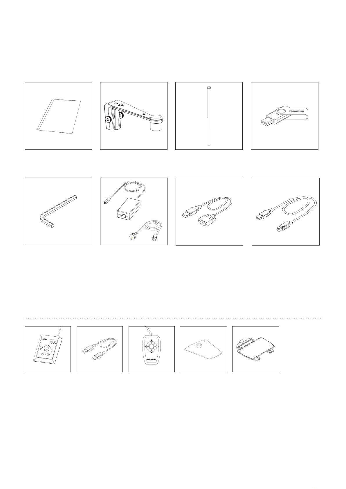
Manual
HDMI - DVI CableHexagon Tool
Base XY table
Power Supply
Camera Arm USB Memory Stick
USB 3.0 A-B Cable
Rod, Washers, Screws
XPLUS FHD control box XKEY Control box
5. yOu HaVE RECEiVED
OpTiOns
HDMI - HDMI cable
4
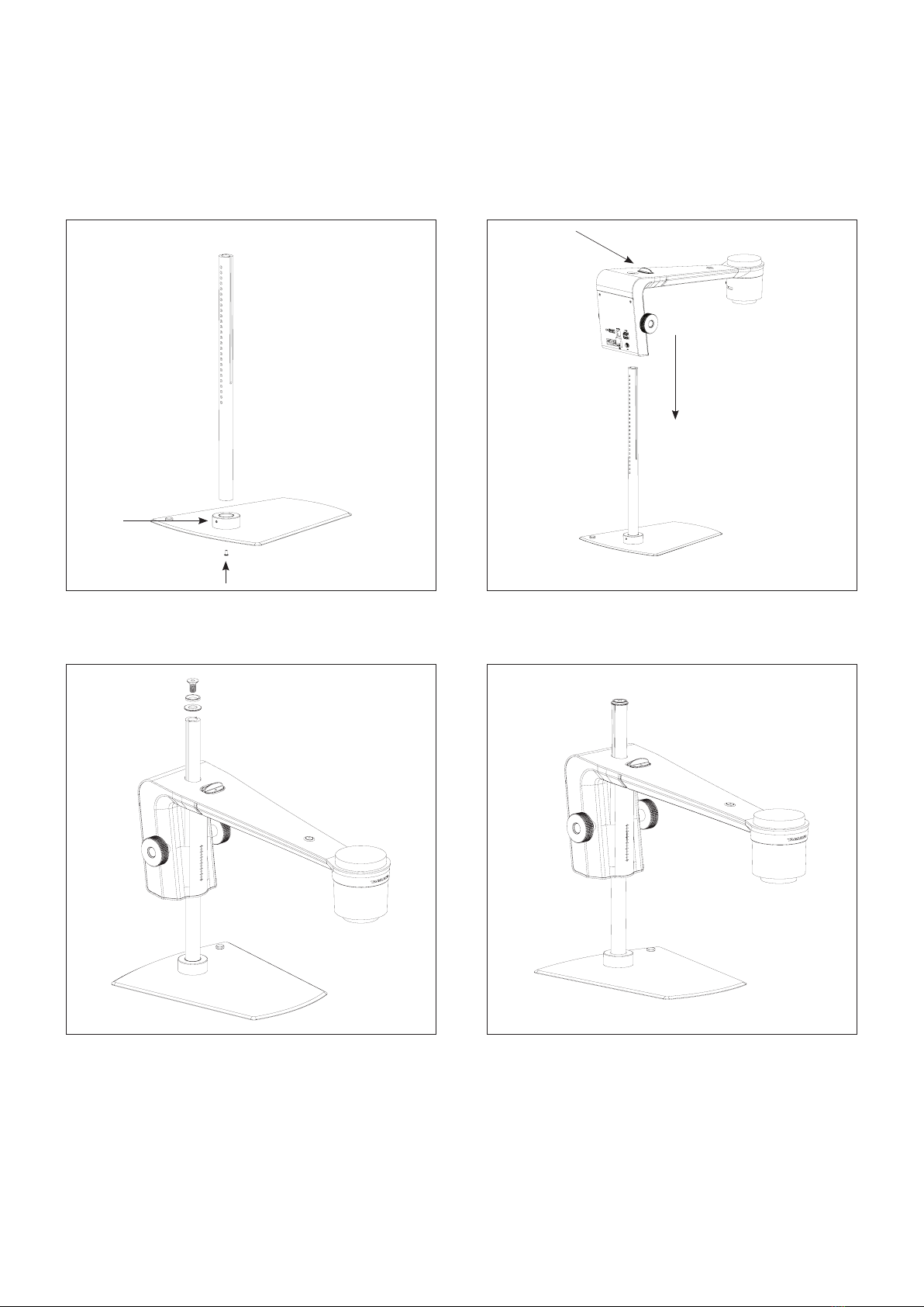
Assemble base and rod with the screw. Tighten the rod both below
the base vertically and horizontally on top of the base
Fasten the two washers with the screw on top of the rod
Pull the button and place the camera arm on the rod
The complete microscope with base
6. assEmBlinG
assEmBlinG | BasE (1/2)
How to install video: tagarno.com/video-tutorials/how-to-install-tagarno-trend.mp4
5
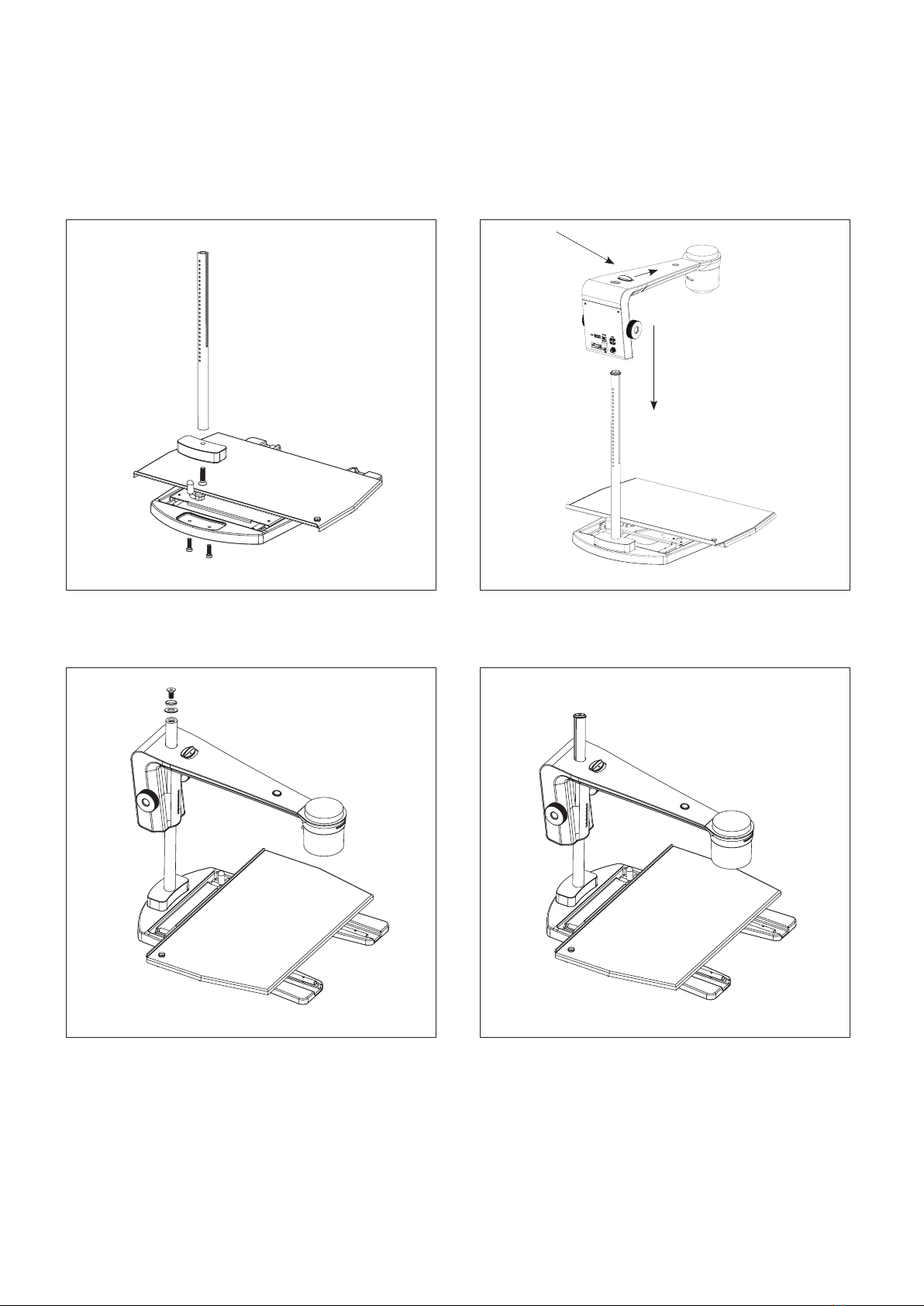
assEmBlinG | xy TaBlE (2/2)
Assemble XY table, block and rod with three screws
Fasten the two washers with the screw on top of the rod
Pull the button and place the camera arm on the rod
The complete microscope with XY Table
7.
6
6.
1.
4.
5.
8.
2.
3.
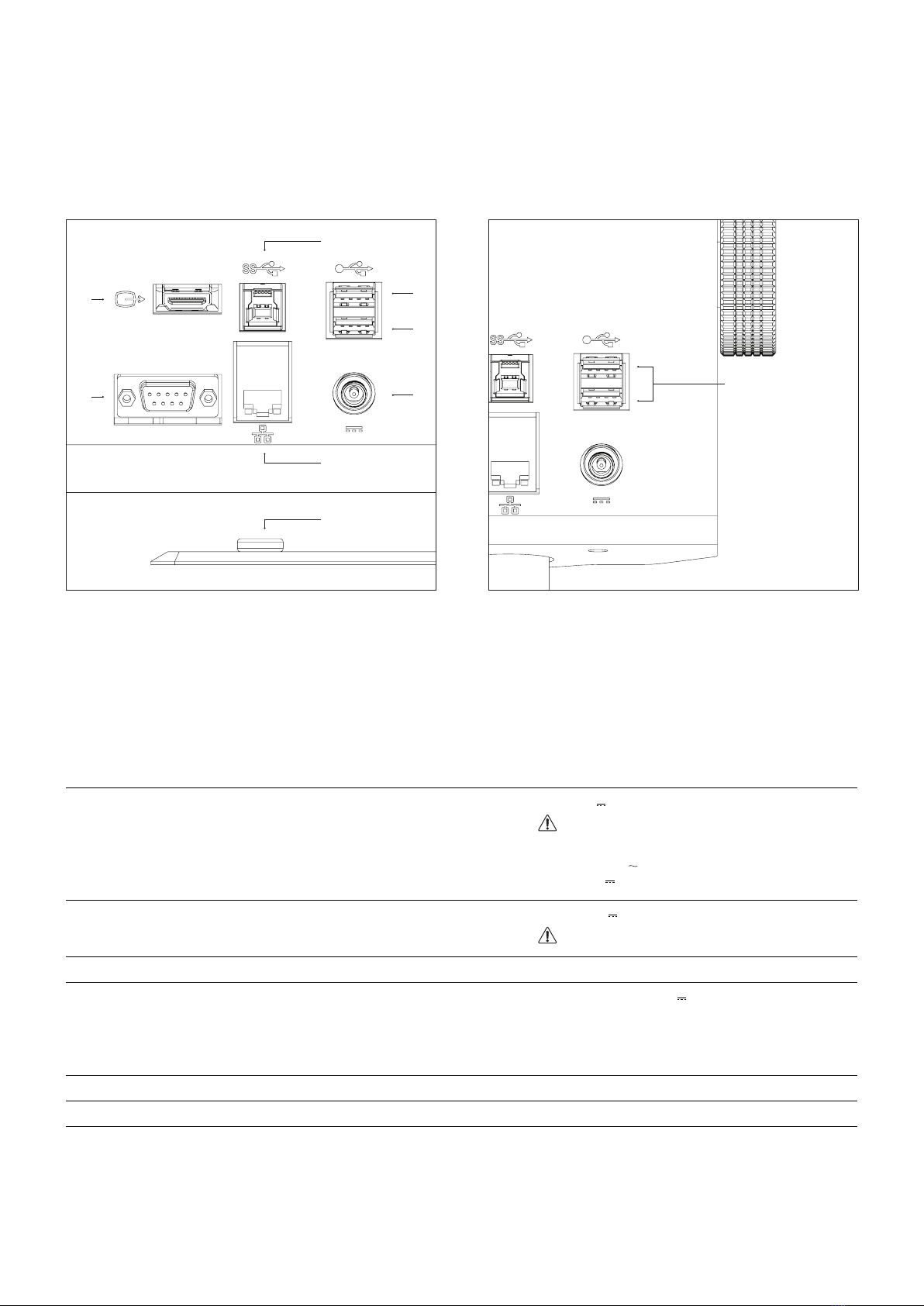
Connector Description Type Connect to Specication
1 Power supply
(DC)
DC Jack Power socket Input: 12V 1.7A
Use only the power supply provided by TAGARNO:
Brand/Model: Mean Well/GSM40A12
Input: 100-240V 1.0-0.5A, 50-60Hz
Output: 12V 3.34A Max
2 Control box D-SUB 9-Pin Female Control box Output: 3.3V 6A Max
Use only control boxes supplied by TAGARNO
3 Output HDMI Standard Type A Monitor HDMI Out 1080p60
4+5 USB 2.0 input USB 2.0 Type A Socket Keyboard
Mouse
USB key
USB hard drive
Barcode scanner
USB 2.0 Host. Output: 5V 500mA
6 USB 3.0 output USB 3.0 Type B Socket Computer USB 3.0 Device. Self-powered
7 Ethernet RJ-45 Ethernet wall socket Ethernet LAN, 100BASE-TX/1000BASE-T
8 ESD Snap Socket, 10mm ESD Grounding point ESD Grounding point. Only black models
COnnECTinG | BasE + xy TaBlE (1/3)
Connect USB cable, control box, monitor, Ethernet and power supply
in that order.
7. COnnECTinG
Connect keyboard and mouse in the USB 2.0 inputs (only for use with
TMA). Keyboard and mouse need to be HID compliant.
You can also use the USB inputs for a USB key, USB hard drive
and/or barcode scanner.
If necessary use a USB hub to get multiple USB ports.
USB 2.0 input
Keyboard
Mouse
USB key
USB hard drive
Barcode scanner

7
8. 8.
Connect ESD grounding cord (electrostatic discharge)
Only black models
Connect ESD grounding cord (electrostatic discharge)
Only black models
COnnECTinG | EsD (2/3)

8
Splitter box
DVI out DVI out
DVI in Power in
The microscope an be connected to multiple monitors by adding
an active signal splitter between the TAGARNO and the monitors
HDMI - DVI cable
Live image
The microscope can be connected directly to a monitor
Live image Live image
HDMI - DVI cable
Live image
/ image capture
Live image and image capturing through USB3.0 / 3rd part software.
See system recommended (third-party) under system requirements.
You are still able to connect monitor(s) as described above.
USB3.0
COnnECTinG | COmBinaTiOns (3/3)

9
1.
2.
OpERaTiOn | BasE + xy TaBlE (1/3)
Place the camera arm in the appropriate height according to the
lens you are using
Adjust the friction tension to set your personal preference
Power on/off
8. OpERaTiOn
1. Use the pin to rotate the camera inside the camera head
2. Tilt the camera head vertically to each side
How to use video: tagarno.com/video-tutorials/how-to-use-tagarno-trend.mp4
10
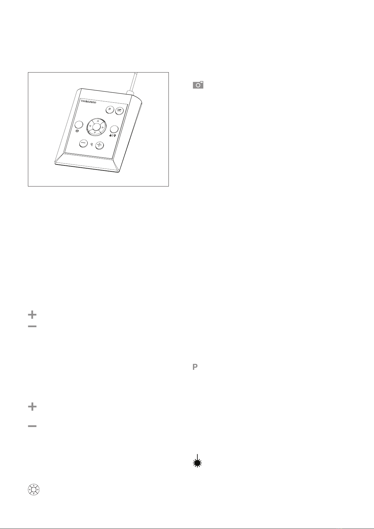
XPLUS FHD Control box for TAGARNO FHD functions.
Do only connect equipment distributed by TAGARNO.
Dimensions
H: 45mm/1.8" | W: 120mm/4.7" | D: 150mm/5.9".
On screen display (OSD)
The on-screen display provides you with the relevant information
when you push a button on the control box or Setup menu.
For instance if you change the level of magnication, the white
balance, iris, etc. In this way you always know which function you
are activating and which parameters you are using.
Zoom
Push this button on the control box to zoom in.
Push this button on the control box to zoom out.
The magnication level will show via On Screen Display.
Manual Focus
Turn autofocus off by pushing both zoom buttons (plus
and minus) on the control box at the same time until you
hear a beep. You can now adjust focus manually with the
help of the zoom buttons.
Push this button on the control box to adjust focus if you
wish to focus on something very close.
Push this button on the control box to adjust focus if you
wish to focus on something that is farther away.
To turn the autofocus on again, simply push both zoom
buttons (plus and minus) at the same time until you hear
a beep. The focus values will show via On Screen Display.
Setup Menu
Access the Setup menu by pressing the round center
button for 1 second. See separate section regarding
the Setup menu.
Snapshot Function
To take a picture and transfer it to USB or your microscope
internal storage, press the image capture button until you hear
a beep. Long press on the same button will save an image with
graphics, causing the live image to freeze for a few seconds.
This button also turns Auto Snapshot on/off when activated via
the Setup menu.
When taking a picture an information window will appear for a
few seconds showing the le name and storage location.
The image will be saved on the inserted USB memory stick.
If a USB memory stick is not attached, the image is saved
internally on the microscope, provided the share le mode is
turned on. Otherwise an error message will appear and you are
not able to save images.
To access the les on the microscope, make sure the Ethernet
cable is correctly connected and follow descriptions below.
NB: The serial number is available on the system label and via the
System information window in the microscope Setup menu.
Access les with Windows operation system:
• Open the File Explorer and type: \\tagarno-snxxxxx
Access les with macOS operation system:
• Open the Connect to server window and type:
smb://tagarno-snxxxxx/
• Press connect
In both cases a window will appear and you can type:
• User name: \public (Windows) or public (MAC)
• Password: pub1234
Double click the images folder and you will be able to save, view,
copy, move and rename images.
Memory Function (Preset Button)
To save a favourite setting, press the "P" button.
A Preset Manager menu appears. Here you can choose which
of the 4 presets to use/overwrite, this is done by marking and
choosing save for the given preset.
To use a preset, simply press "P" and press the center button to
choose the preset you want to recall.
The preset values will show via On Screen Display.
Laser pointer (TAGARNO FHD TREND)
Press this button to turn the laser pointer on/off.
You will hear a warning when turning the laser pointer on.
NB! Never look directly into the laser pointer.
If you are using another TAGARNO unit than TAGARNO FHD
TREND, a window on the screen will provide you with information.
OpERaTiOn | xplus FHD COnTROl BOx (2/3)
Other manuals for FHD TREND
1
This manual suits for next models
1
Table of contents
Other tagarno Microscope manuals


Popular Microscope manuals by other brands


VWR
VWR VisiScope 384 Series instruction manual

Nikon
Nikon ECLIPSE E200 POL instructions

Leica
Leica DI C800 User's manual & installation instructions

ThermoFisher Scientific
ThermoFisher Scientific Continuµm manual

ThermoFisher Scientific
ThermoFisher Scientific Continuµm manual

Olympus
Olympus SZ61 instructions