Taiwan King Strong TP01-S User manual

Taiwan King Strong
Powered Wheelchair TP01-S
Owner’s Manual
“Caution: Federal law restricts this device to
sale by or on the order of a practitioner licensed
by the law of the State in which he/she
practices.”

________
TABLE OF CONTENT
________
1.
1.1.
1. TP 01-S: Foldable Type Framework
1.1. Feature
1.2. Specifications
1.3. Outline:
1.4. Assembling
1.5. Disassembling
2.
2.2.
2. Caution
3.
3.3.
3. Controller Description & Security Function
4.
4.4.
4. Operation guide
5.
5.5.
5. Battery Charger
6.
6.6.
6. Maintenance & Guarantee
7. EMC Statement
P1

1.1 Feature :
1.1.1.
The controller position can be adjusted upward,
downward, forward and backward, it’s according to
user’s need.
1.1.2.
Left hand or right hand drive is available at user’s
option.
1.1.3.
Flip-back and height adjustable armrest is provided.
(1.1.3A, 1.1.4A)
1.1.4.
Safety belt is provided. (1.1.5A)
1.1.5.
Larger front wheels are adapted. It provides good
ability of climbing the curb and crossing the groove.
(1.1.6A)
1.1.6.
Legs are detachable. Only a small space is needed
for transportation. (1.1.7A)
P2

1.2. Specification:
1.2.1. Frame Material: high-quality aluminum pipe
1.2.2. Framework: foldable
1.2.3. Motor output: 320W * 24V * 2pcs
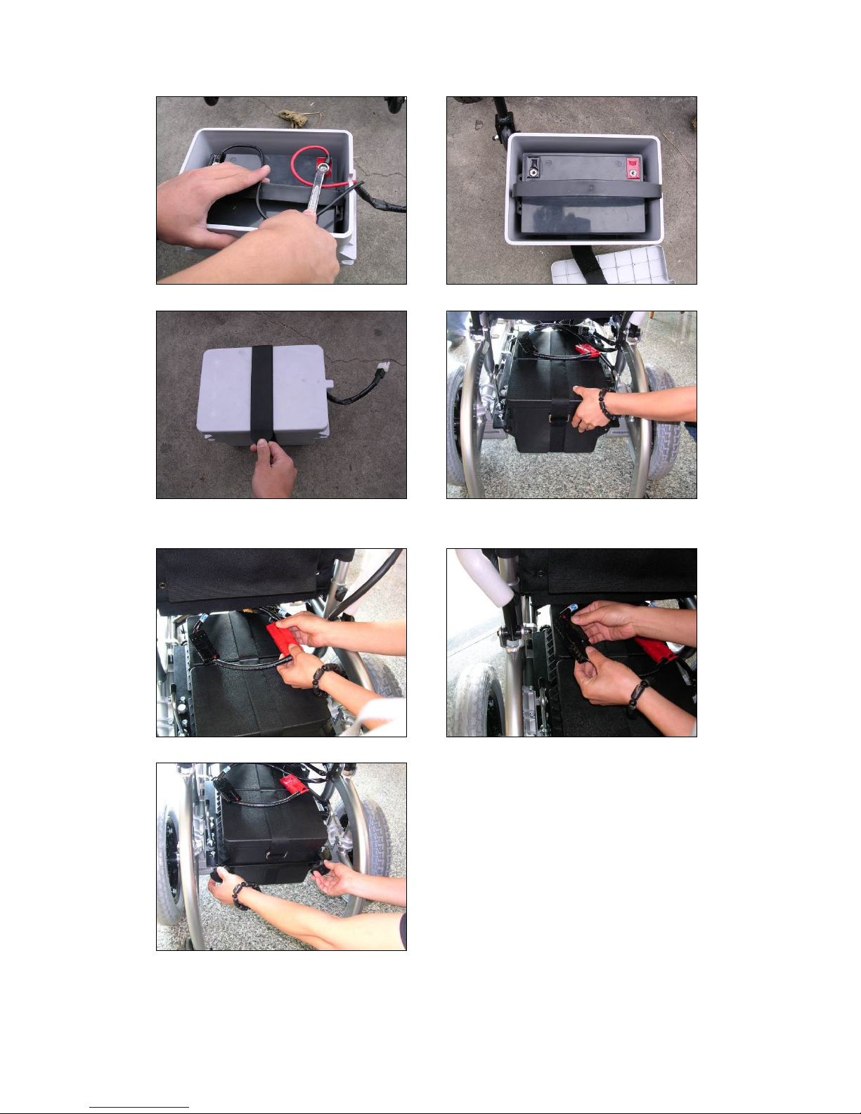
1.2.4. Battery: 36AH * 12V * 2pcs
1.2.5. Charger: DC24V, 5Amps,European connector
1.2.6. Brake: Solenoid brakes
1.2.7. Max. speed: 8 km/hour
1.2.8. Continuous trip distance: 25 km
1.2.9. Climbing ability:
::
:12 degree
1.2.10. Casters: 8” * 2” / 200 * 50 PU tyre
1.2.11. Rear wheel: 12-1/2” x 2 aluminum wheel , PU tyre
1.2.12. Obstable ability: 1”
1.2.13. Ground Clearance : 4”
1.2.14. Seat depth: 16”
1.2.15. Seat height:18”~ 20”(US standard)
1.2.16. Seat width: 16”, 17”, 18”, The height of Back: 18”
1.2.17. Armrest height: 8”,can be adjusted to 19cm-29cm
1.2.18. Max. loading: 130kgs / 260 lbs
1.2.19. Net weight: 64kgs (with battery)
P3

1.3. Outline: TP01-S
FRONT VIEW
Backrest Armrest
Controller
Rear wheel
Footplate
Front caster
P4

1.1.3A 1.1.4A
1.1.5A 1.1.6A
1.1.7A
P5

(FIG .1.4A) (FIG .1.4B)
(FIG .1.4C) (FIG .1.4D)
(FIG .1.4E) (FIG .1.4F)
(FIG .1.4G)
P6

(FIG . 1.5A) (FIG . 1.5B)
(FIG . 1.5C) (FIG . 1.5D)
(FIG . 1.5E) (FIG . 1.5F)
P7

1.4. Assembling
:
1.4.1 Connect the wire wit the battery. (FIG 1.4.A)
1.4.2 Put the battery into battery box. (FIG 1.4.B)
1.4.3 Use the straps to fasten the upper and under seats of the battery
box. (FIG 1.4.C)
1.4.4 Put the battery box unto the battery rods of the frame.(FIG
1.4.D)
1.4.5 Connect the joints of the two battery boxes. (FIG 1.4.E)
1.4.6 Plug the battery joint into the joint of the controller. (FIG 1.4.F)
1.4.7 Fasten the nut. (FIG 1.4.G)
1.4.8 Insert the footplate tube in, and push the tube from outside in to
its place.
1.4.9 Loosen the bolt on the tube of footplate and adjust to a most
comfortable position between the seat and the footplate, then
you can fasten the bolt.
1.4.10 Rotate the clutch lever of the gearbox backward to connect the
drive gear.
1.4.11 Turn on the power(press the power button), the battery gauge
will be turn on, the power system is standing by.
Do not operate this electric wheelchair without first reading and
understanding this manual.
P8

1.5 .Disassembling
1.5.1 Turn off the power(press the power button again), the battery
gauge will be turn off.
1.5.2 Disconnect the main cable from controller. If need to remove the
controller. You must loose the holder of controller.
1.5.3 Separate the joint of controller stick from the battery joint.
(FIG . 1.5.A)
1.5.4 Separate the joints of the two battery. (FIG . 1.5.B)
1.5.5 Loosen the nuts. (FIG . 1.5.C)
1.5.6 Take away the two batteries from the battery rods. (FIG .
1.5.D)
1.5.7 Loosen the straps of the battery box. (FIG . 1.5.E)
1.5.8 Unwind the wires of the battery ,and the battery can be taken
off. (FIG . 1.5F FIG . 1.5G)
1.5.9 Take off the footplate. If the footplate tube needs to be taken
down, press down the release and push the tube outward to
take off the piece.(1.1.7A)
1.5.10 Gather up the wheelchair.
P9

2. Caution:
2.1. Always make sure the power is off when you are getting off or
on the power wheelchair.
2.2. Before operation your wheelchair, make sure that you have
enough power to complete you intended trip, if the battery is
not charged sufficiently please don’t go outdoor for long
distance operation.
2.3. To keep battery life longer, please do charge your battery after
every trip is suggested. If not drive for a long time, you have to
do a full charge on your battery per 1 months.
2.4. If the battery gauge goes to RED light, charging the battery as
soon as possible. Deep discharging the battery will damage the
battery and can shorten its life.
2.5. When the battery is old and deteriorated, the battery gauge
will go down quickly.
2.6. In cold weather, the battery capacity will decrease.
2.7. When you are charging the battery, please make sure that the
input-voltage (115V/230V) switch of your charger must match
your power source.
2.8. Avoid unnecessarily moving to the power-chair.
2.9. Please fasten the safety belt while driving and check the proper
position of anti-tipper.
2.10. Our products suitable at condition where temperature is
maintain within 0~50℃
℃℃
℃.
2.11. Disassemble the controller, motor or charger by user-self is
inhibited, the dealer will not take any responsibility on
maintenance and guarantee of this product when user does
that.
P10

3. Controller description & Security function:
3.1. Controller Description:
A B C
A: Down-speed button F: Up-speed button
B: Buzzer button G: Joystick
C: Battery gauge & Diagnostics indicators*
**
*
D: Speed indicator
E: Power button
P11
D
E
F
G

* Battery gauge & Diagnostics indicators:
When the indicators turn on, it’s in the Battery gauge situation:
Green lights: the battery has full capacity.
Orange lights: do not drive power-chair for long trip is suggested.
Red lights: the power-chair should be charged as soon as possible.
When the indicators become flashing, the number of flashing bar indicates the
possible fault. Description below:
P12

3.2. Security Function:
3.2.1. The forward/backward/turn speed, acceleration and
deceleration can be programmable.
3.2.2. Thermal overload protection.
3.2.3. Current overload protection.
3.2.4. The fault diagnostics of the controller. (Ref. Last page).
3.2.5. The power-chair will not turn on while charging the
batteries
.
P13

4. Operation Guide:
4.1. Turn on the power (Press the power button), and the battery
gauge will turn on.
4.2. Rotate the clutch lever of gearbox inward to connect the drive.
4.3. Start to steer, moving the joystick to drive forward, backward,
left and right. If you want to stop the wheelchair, just release
the joystick, it will return to the center position to stop the
power-chair automatically.
4.4. We suggest the beginner and the older people to operate the
power-chair in low speed for a certain period before going into
high sped.
4.5. Considering the user’s safety, the speed will be reduced in half
when the power-chair under turning conditions.
4.6. When you drive your power-chair on a slope in climbing
condition, push the joystick entirely forward to keep the
power-chair continuously climbing until you reach the top of
the slope. While the power-chair is climbing a slope is steep,
transfer the gravity of the power-chair to front by leaning your
body forward to prevent the front wheels from lifting.
4.7. When you operate your power-chair down a slope, drive is
slowly and prepare for an emergency stop if you feel difficult to
control the power-chair. If the speed increase, release the
joystick to let it return to the center position to slow down or
stop, then start again slowly.
4.8. Flip-back armrest: Release the lock-pin and lift the armrest
back to get on or get off the power-chair more convenient.
4.9. Loosen the bolt on the tube of footplate and adjust to a most
comfortable position between the seat and the footplate, then
you can fasten the bolt.
P14

5. Battery Charger
1 2 3 4 5
6 7 8
1. Output fuse of anti-polarity counter
2. Charge cable
3. Power switch
4. 115V/230V switch
5. Socket of power cable
6. Radiating fan
7. Red light: the power input indicator
8. Yellow light: being charged
9. Green light: charging finished
5.1. Specifications:
Mode
Specifications HP 8204A
Input Voltage
115V/230V Option Switch
115V(95V-132V)/230V(180V-2
64V)
Output Voltage 24V
Output Current 5A Continuous
Max. Output Voltage 31V
P15

Mode
Specifications HP 8204A
Protection Against Over-Voltage Above 32.5V-Automatic
Shut-off
Protection Against Overload Above 8A-Automatic Shut-off
Protection Against Short Circuit Output Fuse Severs of Shut-off
Automatically
Environmental Temperature of use
-10°~50°
Environmental Temperature of
Preservation -25°~85°
Dimensions 180mm(L) x 93mm (W) x
53mm (H)
Weight 0.83kg
Approvals UL, CSA, CE, TUV, JAPAN
5.2. Features:
5.2.1. Checks the battery connection automatically.
5.2.2. Automatic full charge maintenance – free sealed lead-acid
battery.
5.2.3. Monitor in all procedure until the battery is fully charged.
5.2.4. For protecting exhausted batteries, slow charge in the
beginning and fast charge until it goes up to the normal
voltage.
5.2.5. Compact, portable and light-weighted.
5.2.6. Approvals: UL, CSA, CE, TUV, JAPAN(T-mark)
5.3. Operation instruction (Please follow the steps):
5.3.1. Check current type of input (115V or 230v), and then switch
accordingly at the charger.
5.3.2. Check if the battery is 24V/12AH above lead acid battery.
5.3.3. Please switch the AC power input “Off” before the battery
cable is connected.
Check if the negative and positive polar of the charger matches to the
battery.
P16

5.3.4. After completing the steps as the above, switch the AC input
button to “1”. The fan starts turning, and the LEDs red and
yellow are on means the charger works normally. For the
exceptional, please turn off the charger instantly and repeat
step 1-4 and restart it.
5.3.5. The cross-blink between Led yellow and Led green is normal
while the charger is fully charged and the Led green is stable
on.
5.4.usage environment:
::
:
5.4.1. Keep the charger and other objects above 5cm to reduce the
heat.
5.4.2. Do not use it on the wet and dirty place.
5.4.3. Do not put charger on the battery.
5.4.4. Prevent charger from shock.
5.5. Note:
5.5.1. Check the ground wire well for safety if the input wire of
charger is equipped with ground wire.
5.5.2. Check if the output-DC voltage corresponds to the battery
type and voltage. Wrong voltage and battery type would
explode the battery and wound the users.
5.5.3. Switch off the charger to “O” position before connecting the
charging wire and battery.
5.5.4. Avoid exposing charger in rain, water and damp conditions.
5.5.5. Contact the sales agent when the charger stays in yellow
after charging more than 12 hours.
P17

6. Maintenance & Warranty:
6.1. Maintenance (consuming parts):
6.1.1. Battery: please charge instantly after long distance driving
to prolong the battery. And do the full charge per 1 month if
long time not drive. Please use maintenance/water-free
battery to avoid trouble.
6.1.2. Motor: carbon brush connector & brakes are consuming
parts, please replace them regularly.
6.1.3. Tyre: check front/rear tyre pressure regularly, replace them
when worn out.
6.2. Warranty:
6.2.1. Main frame: 3 years.(consuming parts not include)
6.2.2. Controller: 1 year.
6.2.3. Charger: 1 year .
*
The warranty is given for use within normal operation condition, it
does not cover accidental damage, or problem caused by user’s neglect
or misuse.
P18
How to check electrical brakes:
This test should be carried out on a level floor with at least one
meter clear space around the power-chair.
Power on the controller, check that after 1second the battery gauge
remains on or flashed slowly. Pushing the joystick forward slowly
until you fear the electrical braked operate. The power-chair may start
to move. Immediately release the joystick, you must be able to hear
each electrical brake operate within a few seconds. Repeat the test
three times, pushing the joystick backward, left and right respectively.

7. EMC statements
This portion of the content will provide the user with basic information
that describes the problems with EMI, known sources of EMI, protective
measures either to lessen the possibility or exposure or to minimize the
degree of exposure, and suggested action should unexpected or erratic
movement occur.
Caution: It is very important that you read this information regarding
the possible effects of electromagnetic interference on your electric TP
01
-
S
WHEELCHAIR.
■ ELECTROMAGNETIC INTERFERENCE (EMI) FROM RADIO
WAVE
SOURCES
Powered vehicle may be susceptible to electromagnetic interference
(EMI), which is interfering electromagnetic energy (EM) emitted from
sources such as radio stations, TV stations, amateur radio (HAM)
transmitters, two-way radios, and cellular phones. The interference
(from radio wave sources) can cause the powered vehicle to release its
brakes, move by itself, or move in unintended directions. It can also
permanently damage the powered vehicle’s control system. The
intensity of the interfering EM energy can be measured in volts per
meter (V/m). Each powered vehicle can resist EMI up to a certain
intensity. This is called its “immunity level”. The higher the
immunity level the greater the protection. At this time, current
technology is capable of achieving at least a 20 V/m immunity level,
which would provide useful protection from the more common sources
of radiated EMI. This powered vehicle model as shipped, with no
further modification, has an immunity level of 20 V/m without any
accessories.
There are a number of sources of relatively intense electromagnetic
fields in the everyday environment. Some of these sources are
obvious and easy to avoid. Others are not apparent and exposure is
unavoidable. However, we believe that by following the warning
listed below, your risk to EMI will be minimized.
The sources of radiated EMI can be broadly classified into three types:
1. Hand-held portable transceivers ( transmitter-receivers with the
antenna mounted directly on the transmitting unit.
Examples include: citizens band (CB) radios, “ walkie talkie”, security, fire, and
police transceivers, cellular telephones and other personal communication
devices.
P19
Table of contents
Popular Wheelchair manuals by other brands

Comfort Company
Comfort Company FLEXION FOOTBOX SINGLE manual

AAT
AAT Movilino user manual

Breezy
Breezy Emineo Assembly instruction

Sunrise Medical
Sunrise Medical Quickie installation instructions

Handicare
Handicare IBIS XA Service manual

Stealth Products
Stealth Products Stealth Positioning Pelvic Belts manual