taiyo RX-802AS User manual

PB
1
TAIYO ELECTRIC IND.CO.,LTD.
TEMPERATURE CONTROLLED
LEAD-FREE SOLDERING STATION
RX-802AS
Thank you for buying a goot soldering station. Your new soldering station has been
engineered and manufactured to the goot high standards for dependability, ease of
operation, and operator safety. If you follow the instructions and safety precautions in this
manual and use the soldering station properly and only for what it is intended, you will enjoy
years of safe, reliable service. Thank you again for buying a goot soldering station.
WARNING
Before using the soldering station, read the Operation Manual.
Failure to follow the safety precautions and instructions in this
manual could result in serious injury and property damage.
KEEP THIS MANUAL FOR FUTURE REFERENCE
TAIYO ELECTRIC IND.CO.,LTD.
OPERATION MANUAL ver.
4
Tips not included
Tips sold separately

TAIYO ELECTRIC IND.CO.,LTD.
2
WARNING
Failure to obey a safety warning could result in serious
injury or death to yourself or to others. Always follow the
safety precautions to reduce the risk of electric shock, fire
or personal injury.
CAUTION
Failure to obey a safety caution may result in a minor or
moderate injury to yourself or to others. Always follow the
safety precautions to reduce the risk of electric shock, fire
or personal injury.
Safety Mark Definitions
Following the WARNINGS and CAUTIONS in this manual will allow for the safe
and proper use of the soldering station, and should protect the operator from
injury and operators' property against damage.

3
TAIYO ELECTRIC IND.CO.,LTD. 3
1Table of Contents
1. Table of Contents / Specifications......................................................................3
2. Introduction ...........................................................................................4
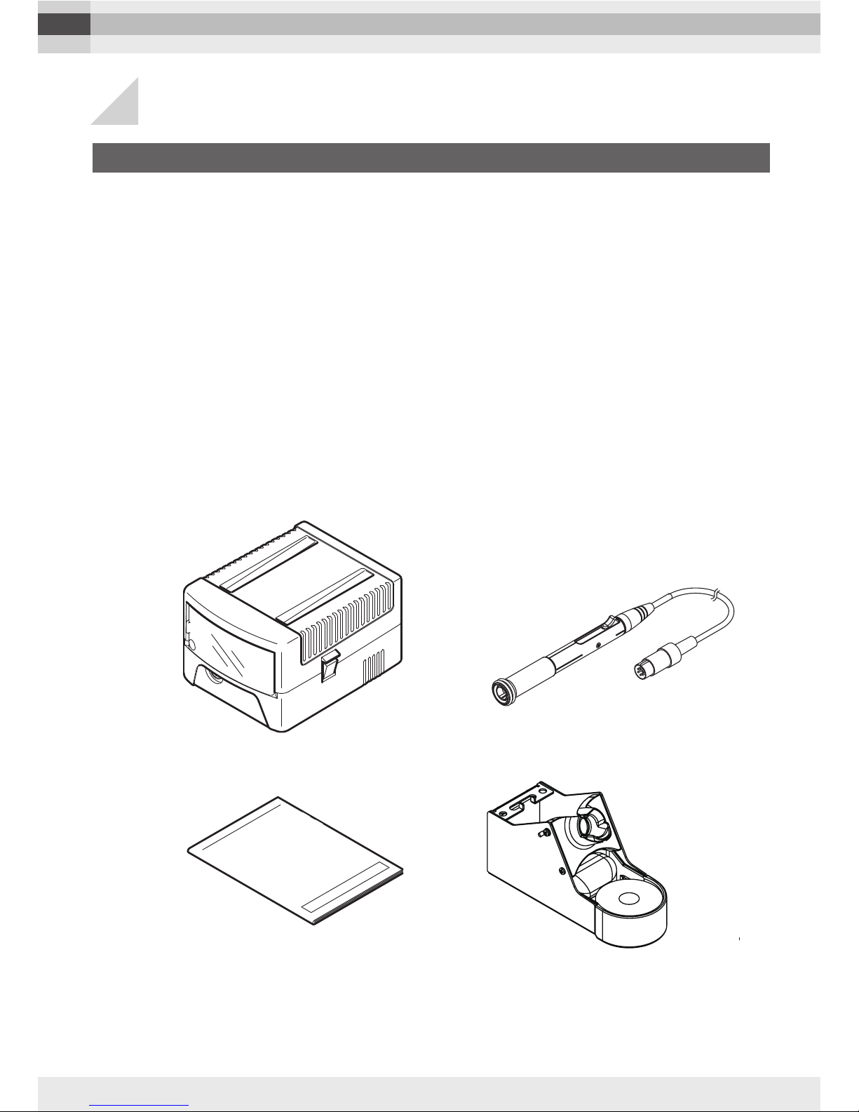
2.1 Unpacking ...........................................................................................4
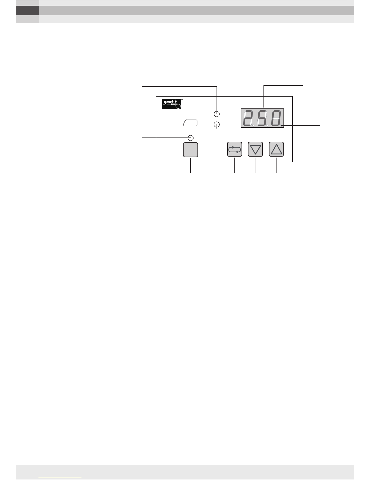
2.2 Name of Parts ...........................................................................................5
2.3 Soldering Iron Stand ST-21 Instructions................................................................7
3. Rules for Safe Operation.........................................................................................8
4. Operation Instructions ......................................................................................... 10
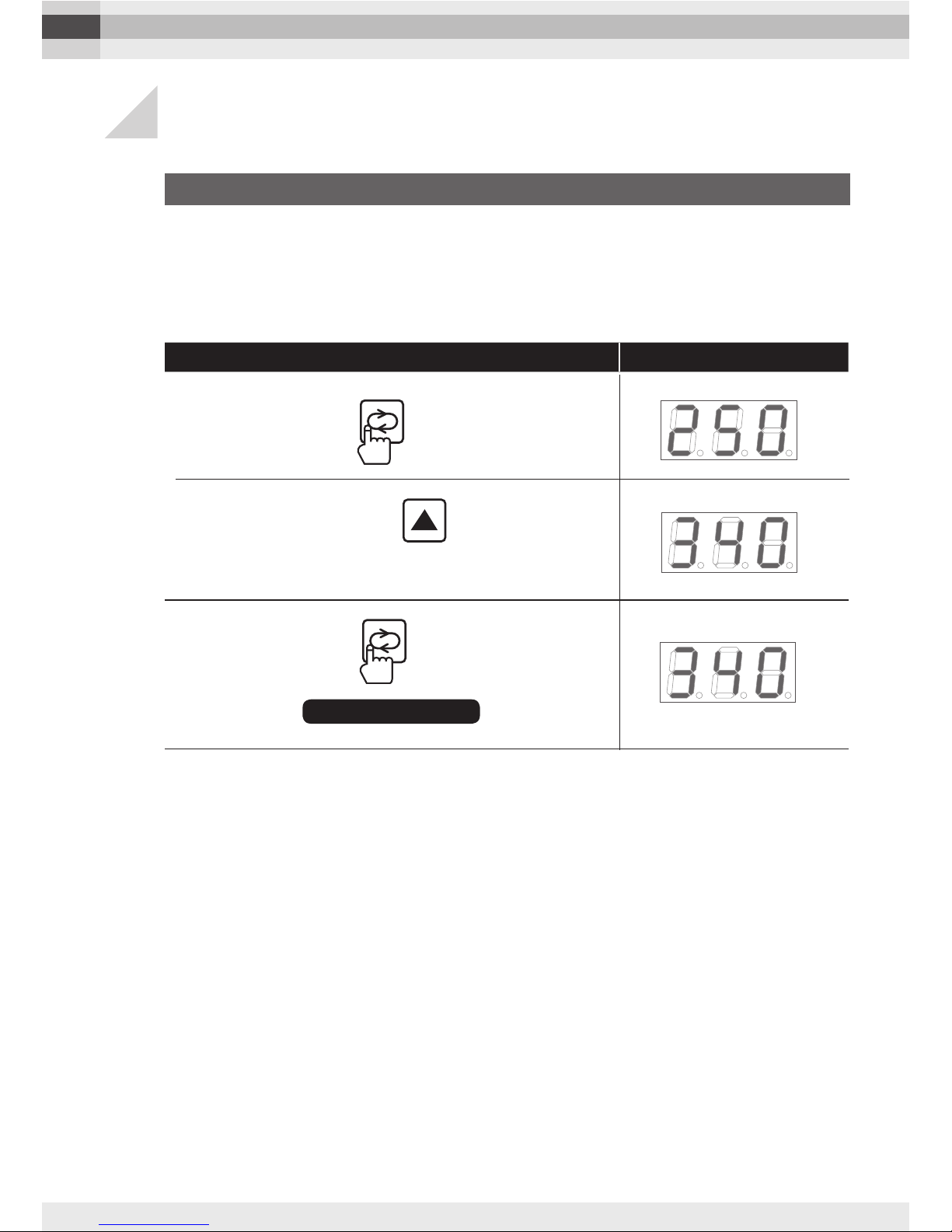
4.1 Changing the Set Temperature.................................................................... 10
4.2 Calibration of the Tip Temperature.............................................................. 11
4.3 Calibration Function ..................................................................................... 12
4.4 Sleep Function ......................................................................................... 13
4.5 Setting the Shutdown Function ................................................................... 16
4.6 Setting the Soldering -time Alarm ............................................................... 17
4.7 Setting the Temperature Range for the Alarm............................................ 18
4.8 Setting the Alarm Sound .............................................................................. 19
4.9 Setting the Temperature Display.................................................................20
4.10 Key Lock Function ........................................................................................21
4.11 How to Restore the Default Settings ...........................................................24
5. Maintenance .........................................................................................26
5.1 How to Change the Tip .................................................................................26
5.2 How to Change the Grip Rubber ..................................................................27
5.3 Housing Cleaning .........................................................................................27
5.4 How to Use and Maintain a Lead-Free Soldering Iron...............................27
6. Troubleshooting .........................................................................................28
7. Replacement Tips .........................................................................................29
8. Replacement Parts .........................................................................................30
9. Parameters .........................................................................................31
MODEL RX-802AS
Voltage 110, 120, 130, 220, 230, 240V AC
Power Consumption 80W
Soldering Iron Voltage/ Wattage 24V AC/72W
Temperature Setting Range 50°C (122°F)—450°C (842°F)
Dimensions Soldering Unit 158mm (w/o cord bushing)
Control Unit 115 mm (W) X 98 (H) X146(D) mm
Weight Soldering Unit Approx. 28g (w/o cord)
Control Unit Approx. 1.8kg (w/o cord)
Control Unit to Soldering Unit cord Length 1.2m
AC Power Cord Length 1.2m 3 core cord (ground plug)
Leak Voltage Less than 2mV
Ground Resistance Less than 2Ω
Accessories Soldering Iron Stand ST-21
Specifications
TAIYO ELECTRIC IND.CO.,LTD.

TAIYO ELECTRIC IND.CO.,LTD.
RX-802AS
Operation Manual Soldering
Iron Stand : ST-21
Control Unit
Soldering Unit : RX-80GAS
Packing List
■Control Unit
■ Soldering Unit : RX-80GAS
■ Soldering Iron Stand :ST-21
■ Operation Manual
Please make sure that all the items listed below are included, and that the soldering station
(control unit and soldering unit) function properly. If any items are missing or damaged, please
contact your goot distributor. Please store the packaging for future shipment or repair.
2-1 Unpacking
TAIYO ELECTRIC IND.CO.,LTD.
4
2Introduction

5
TAIYO ELECTRIC IND.CO.,LTD. 5
TAIYO ELECTRIC IND.CO.,LTD.
KEY
LOCK
RX-802
HEAT
SLEEP
TEMP. ˚C
AS
FRONT VIEW SIDE VIEW
Operation Panel
Cover
Power Cord
Rating LabelPower Switch
Tip (Sold separately)
Slide Lever
Grip Rubber
Soldering Unit
Connector
Grip Adapter
Output Terminal for
Soldering Unit
2-2 Name of Parts
KEY
LOCK
RX-802
HEAT
SLEEP
TEMP. ˚C
AS
FRONT VIEW SIDE VIEW
Operation Panel
Cover
Power Cord
Rating LabelPower Switch
Tip (Sold separately)
Slide Lever
Grip Rubber
Soldering Unit
Connector
Grip Adapter
Output Terminal for
Soldering Unit
KEY
LOCK
RX-802
HEAT
SLEEP
TEMP. ˚C
AS
FRONT VIEW SIDE VIEW
Operation Panel
Cover
Power Cord
Rating LabelPower Switch
Tip (Sold separately)
Slide Lever
Grip Rubber
Soldering Unit
Connector
Grip Adapter
Output Terminal for
Soldering Unit
CAUTION
[4-2] calibration of the tip temperature is
requires after attaching the tip. Otherwise,
there may be some difference between
the actual tip temperature add the set
temperature of the unit.

TAIYO ELECTRIC IND.CO.,LTD.
6
TAIYO ELECTRIC IND.CO.,LTD.
KEY
LOCK
RX-802 HEAT
SLEEP
TEMP. ˚C
AS
①
⑤
⑥
③
②④
⑦ ⑧ ⑨
1. HEAT lamp
Lights up when the heater is ON.
2. SLEEP lamp
Flashes while setting the SLEEP function. The flashing of the sleep lamp
will increase 30seconds before entering SLEEP mode.
Lights up when the unit enters SLEEP mode.
3. TEMP. display
When the power is turned ON or when SLEEP mode is exited, the TEMP
display shows the tip temperature rise to the set temperature. The TEMP
display shows the set temperature when it is reached.
4. ALARM lamp (to the right of the last digit in the temperature display)
Lights up when the tip temperature is within the DIF range.
Turns off when the tip temperature is out of the DIF range.
Flashes when the tip temperature is out of the upper and lower
temperature limits.
5. KEY LOCK lamp
Flashes while setting the Key Lock function.
Lights up when the unit is in Key Lock mode.
6. KEY LOCK key
Use to set the Key Lock function.
Use to lock and unlock the keypad.
7. SETTING key
This key is pressed when starting and completing the temperature
setting process. It is also used during the parameter changing procedure
to move to the next parameter and to complete the parameter setting
process by pressing continuously for 3 seconds.
8. DOWN key
This key is used to reduce the used to reduce the temperature and
change the parameter.
9. UP key
This key is used to increase the temperature and change the parameter.
■Operation Panel

TAIYO ELECTRIC IND.CO.,LTD.
6
TAIYO ELECTRIC IND.CO.,LTD. 7
Rub the soldering-iron tip on the moistened sponge. Use the hole of the sponge for better
cleaning. Alternatively, push the soldering-iron tip in and out of the brass wool a few
times. Stab, not swipe.
Front Opening
Adjusting Screws
Heat-Resistant
Sponge
ST-53SP
Brass Wool
ST-40BW
ST-21MS
lTo avoid rust, do not pour water on the brass wool. lSponge
tray and holding flange (of the front opening) are made of
phenol. Be aware that extended tip-contact may result in their
deterioration. lRemove the collected solder scrap regularly.
The angle of the front opening can be
adjusted by loosening screws on the side.
Tip Stand ST-21C
WARNING
CAUTION
lHigh temperatures. Handle with care. lTo avoid injury, do not
touch the metal part of the stand. lTo prevent fire, do not use the
ST-21 near flammable substances.
lAlways place the stand on a stable worktable, or other stable
location, to prevent injury or accident from dropping it. lTo avoid
splattering solder scrap, do not swipe the tip of the iron across
the brass wool. This is dangerous. lTo prevent fire or personal
injury, be sure that the stand has cooled sufficiently before
storing it.
INSTRUCTION FOR USE
2-3 Soldering Iron Stand ST-21 Instructions

TAIYO ELECTRIC IND.CO.,LTD.
8
3Rules for Safe Operation
1. DO NOT USE IN DANGEROUS ENVIRONMENTS.
Do not use the soldering station in damp or wet locations or expose it to
external environmental conditions, particularly rain. Never use it in an explosive
atmosphere. The heat from the heater can ignite fumes. Be sure that the work area
is well ventilated.
2.
KEEP CHILDREN AND BYSTANDERS AWAY FROM THE SOLDERING STATION.
Do not let bystanders touch the soldering station. All bystanders should be kept a
safe distance from the work area.
3. USE FOR THE RIGHT JOB.
Your soldering station is an electrical tool used to solder parts and melt solder. Do
not use the soldering station for any other purpose. For example: The soldering
station should never be used to warm water or other liquids.
4. WEAR PROPER APPAREL, SAFETY GLASSES, GLOVES AND MASK.
Do not wear loose clothing (such as a necktie). Tie up long hair. Clothing or hair
can burn on contact with the tip or surrounding heated parts.
5. CONNECT TO THE SPECIFIED AC POWER SUPPLY.
The power voltage for this soldering station is indicated at the back of the control
unit. Never plug the soldering station into any other voltage.
6. DO NOT ABUSE THE POWER CORD AND INSPECT IT PERIODICALLY.
Never carry your soldering station by its power cord or yank the power cord to
disconnect it from the receptacle. Keep the power cord away from heat, oil and
sharp edges.
WARNING
The RX-802AS is an anti-static model. Be sure to
properly ground the soldering station using a grounded
receptacle to prevent electric shocks and anti-static. If
it is not properly grounded, electric shocks will occur. As
the soldering station uses conductive materials, please
be careful not to touch any electrical power source or a
serious injury will result.

9
TAIYO ELECTRIC IND.CO.,LTD. 9
TAIYO ELECTRIC IND.CO.,LTD.
7. USE STAND PROVIDED.
Be sure to use the ST-21 soldering iron stand included with the soldering station.
If this stand is not used, the plastic parts (adapter ring and/or handpiece) of the
soldering iron unit could be damaged. Position the soldering iron stand on a flat
work-surface or bench.
8. CONCERNING THE TIP.
After turning OFF the power switch, allow the tip to cool naturally. Never use any
other method to cool it down. For example: Water should never be poured or
sprinkled on the tip to cool it down.
9. CONCERNING THE POWER CORD.
IF THE POWER CORD IS DAMAGED THEN THE SOLDERING STATION SHOULD BE
RETURNED TO THE DISTRIBUTOR FOR REPLACEMENT.

TAIYO ELECTRIC IND.CO.,LTD.
10
4
1
2
3
Key Operation TEMP Display
NOTE ) If nothing is pressed for 30seconds during setting the temperature, the
temperature on display will be recorded and the display will return to the normal
conditions.
*The set temperature should be set at 50°C(90˚F) higher than the sleep
temperature (see the section 4-4), otherwise you will not be able to set
the set temperature value. (Example: If the set temperature is set at
200°C(392˚F), the sleep temperature must be 150°C(302˚F) or under.
4-1 Changing the Set Temperature
Displays flashes
➔Refer to the Parameters table (on ) for an explanation of the display messages.
Press the key.
Setting completed
Press the
Press and hold the key until the
display shows .
key.
Example: Changing the temperature from 250°C (482°F) to 340°C (644°F).
When the station is shipped the temperature is set at 250°C (482°F). The temperature
can be set from 50°C (122°F) to 450°C (842°F).
*For the steps given in the operation instructions, only °C is used.

11
TAIYO ELECTRIC IND.CO.,LTD. 11
1
2
3
How to set the TIP No.
RX-80HRT-B is mounted in the standard unit. When changing to a different type of
tip, the calibration of the tip temperature is required before starting soldering work.
Otherwise, there may be a difference between the actual tip temperature and the set
temperature of the unit.
Key Operation TEMP Display
Returns to the set
temperature display.
4-2 Calibration of the Tip Temperature
(Example : When using an 1.6D tip, set to TIP No. 2.)
Displays
alternately
Tip No. List
TAIYO ELECTRIC IND.CO.,LTD.
Press the key so that the
Setting completed
Press and hold the key for over
number 2is displayed.
The temperature can be calibrated easily by inputting the TIP number which is engraved on
the tip.
The above tip number (TIP NO.) may be changed without notice, due to design changes, etc.
Be sure to check the actual engraved tip number of your tip (at the base).
Displays
alternately
3 seconds continuously.
Press and hold the key for over
3 seconds continuously.
MODEL TIP SHAPE TIP NO.
RX-80HRT-SB SB 3
RX-80HRT-B B 1
RX-80HRT-2B 2B 1
RX-80HRT-BM BM 1
RX-80HRT-LB LB 2
RX-80HRT-LBJ LBJ 2
RX-80HRT-1BC 1BC 1
RX-80HRT-2.3BC 2.3BC 1
RX-80HRT-3BC 3BC 1
RX-80HRT-0.5C 0.5C 3
RX-80HRT-1C 1C 4
RX-80HRT-2C 2C 4
RX-80HRT-3C 3C 2
RX-80HRT-4C
4C 1
RX-80HRT-4.7C 4.7C 0
MODEL TIP SHAPE TIP NO.
RX-80HRT-2CD 2CD 4
RX-80HRT-3CD 3CD 2
RX-80HRT-0.8D 0.8D 2
RX-80HRT-1.2D 1.2D 2
RX-80HRT-1.6D 1.6D 2
RX-80HRT-2.4D 2.4D 1
RX-80HRT-3.2D 3.2D 1
RX-80HRT-5.4D 5.4D 0
RX-80HRT-3K 3K 1
RX-80HRT-4.5K 4.5K 1
RX-80HRT-5.5K 5.5K 1
RX-80HRT-4.5KH
4.5KH 1

TAIYO ELECTRIC IND.CO.,LTD.
12
TAIYO ELECTRIC IND.CO.,LTD.
1
2
4
How to Calibrate
the Temperature
The RX-802AS can be calibrated using a tip thermometer. Generally speaking, when
measuring the tip temperature of the RX-802AS with a standard tip thermometer, the
measured temperature will usually be lower than that of the actual tip temperature
displayed on the RX-802AS control unit display. This could be because the tip is not
coming into contact properly with the sensor of the tip thermometer. It could also be
because once the tip thermometer comes into contact with the RX-802AS soldering
tip, the metallic parts in the thermometer (for example alumel chromel in the Type-K
thermocouple) conduct heat which transfers away from the RX-802AS tip. This
results in the thermometer indicating a slightly lower temperature than the one in the
RX-802AS display.
Key Operation TEMP Display
4-3 Calibration Function
3
(Example : Where the set temperature is 300°C (572°F),
tip thermometer value is 295°C (563°F), and the calibra-
tion value to be input is 5°C (9°F).)
Press the key once.
Press the key so that 5(˚C)
is displayed.
Displays
alternately
Displays
alternately
Displays
alternately
Returns to the set
temperature display.
Setting completed
Press and hold the key for over
3 seconds continuously.
Press and hold the key for over
3 seconds continuously.
Calibration value is set to 0 before shipping. The tip number must be changed when the different type of
tip is mounted according to 4-2 Calibration of the Tip Temperature.

TAIYO ELECTRIC IND.CO.,LTD.
12 TAIYO ELECTRIC IND.CO.,LTD.
13
The sleep start timer (CT) function automati-
cally lowers the temperature of the tip after a
preset period of inactivity. This function reduc-
es power consumption and helps extend sol-
dering tip life. This sleep function can be used
with the shutdown function (see 4-5) together.
4-4 Sleep Function
CT
SST
Soldering tip temperature
Set temperature
Sleep start
DIF
Operation
DIF (Sensitivity)
Power ON Time
(Sleep start time)
(Sleep setting temp.)
1
2
4
Unit: °C
Key Operation TEMP Display
Set to 200°C (392°F) before shipping.
Example : Changing the sleep temperature
from 200°C (392°F) to 150°C (302°F).
3
Displays
alternately
Displays
alternately
Displays
alternately
Returns to the set
temperature display.
Press and hold the key for over
3 seconds continuously.
Press the key twice.
Press the key, until the display
Setting completed
Press and hold the key for over
3 seconds continuously.
changes to 150.
To use Sleep function manually during the operation, press and hold the key for one second
continuously. (Active Sleep function) While setting the Sleep function, the Sleep lamp will flash.
The flashing of the Sleep lamp will increase 30 seconds before entering Sleep mode.
When the soldering station has entered Sleep mode, the Sleep lamp will change from flashing to
continuously lit, and the display will alternate between “SLP” and the temperature.
When the power is turned ON, no work is started and nothing is pressed on the keypad, the soldering
station will automatically enter Sleep mode either 10 minutes after the power has been turned ON or
in twice the set sleep time (CT), whichever time is longer. However, if soldering is started or keys are
pressed on the control panel, the soldering station will automatically revert to the set sleep start time.
Sleep mode can be exited by rubbing the tip on the moist
sponge. But when Sleep temperature (SST) is 99°C
or below, Sleep mode cannot be exited because the
temperature changing range is too small. To exit Sleep
mode, press any key on the control panel and the tip will
return to the set temperature.

TAIYO ELECTRIC IND.CO.,LTD.
14
TAIYO ELECTRIC IND.CO.,LTD.
1
2
4
Setting the Sleep start
time (CT) Unit: mins.
Key Operation TEMP Display
3
By setting the CT (Sleep start time) to 0.00 the sleep function will be turned off and the
SLEEP lamp will go out.
Set to 5 minutes before shipping.
Example : Changing the sleep start time from 5 to 10 minutes.
Displays
alternately
Displays
alternately
Displays
alternately
Returns to the set
temperature display.
Press and hold the key for over
3 seconds continuously.
Press the key three times.
Press the key, until the display
Setting completed
Press and hold the key for over
3 seconds continuously.
changes from 5to 10.

TAIYO ELECTRIC IND.CO.,LTD.
14 TAIYO ELECTRIC IND.CO.,LTD.
15
1
2
4
Setting the Sleep
Sensitivity (DIF) Unit : °C
Key Operation TEMP Display
3
Example : Changing the Sleep Sensitivity value to 2 °C (3.6°F)
to 3.0°C (5.4°F).
Press and hold the key for over
3 seconds continuously.
Press the key four times.
Returns to the set
temperature display.
Press the key, until the display
Setting completed
Press and hold the key for over
3 seconds continuously.
changes to 3.0.
Displays
alternately
Displays
alternately
Displays
alternately
NOTE )
*If the sleep sensitivity value (DIF) is set too high, there is a possibility that the
sleep function will be activated even during soldering. If this happens, reduce the
sleep sensitivity value.
*Sleep sensitivity value (DIF) can be set anywhere between 0°C (0°F) and 20.0°C
(36.0°F).
*If the sleep sensitivity value (DIF) is set to low, there is a possibility that the sleep
function will not be activated even after passing Sleep Start Time (CT) because
the tip temperature can't be stabilized within the range of DIF. If this happens,
increase the DIF value.

TAIYO ELECTRIC IND.CO.,LTD.
16
TAIYO ELECTRIC IND.CO.,LTD.
When the unit is not operated during the preset time, the unit is automatically shutdown.
Even if the user forgets to turn OFF the unit, this Shutdown function works to keep the
unit inactive, and prevents accidents such as fire.
4-5 Setting the Shutdown Function
CT SUT
DIF
Power ON Time
Soldering tip temperatrue
Operation
(Shutdown start time)
Power OFF
Sleep setting temp.
Set temperature
(Sleep start time)
DIF (Sensitivity)
When using together with Sleep function.
SUT Power OFF
Soldering tip temperatrue
Set temperature
Power ON Time
Operation
DIF
DIF (Sensitivity)
(Shutdown start time)
1
2
4
Key Operation TEMP Display
3
When SUT (Shutdown start time) value is set to 0, the shutdown function is OFF. The
display will alternate between Sdn and the temperature when the unit is in the shutdown
mode. The LED under the one digit on the TEMP window lights when the temperature
Example : Changing the Shutdown start time
from 60 to 30. Unit : mins
Press and hold the key
for over 3 seconds continuously. Displays
alternately
Displays
alternately
Displays
alternately
Press the key, until
the display changes to 30.
Press and hold the key
for over 3 seconds continuously.
Setting completed
Returns to the set
temperature display.
Press the key five times.
Setting the Shutdown
start time (SUT)

TAIYO ELECTRIC IND.CO.,LTD.
16 TAIYO ELECTRIC IND.CO.,LTD.
17
The RX-802AS sounds an alarm, when the soldering iron is left in contact with the
component being soldered past the time set. This function prevents inexperienced
operators from overheating the component.
4-6 Setting the Soldering-time Alarm
1
2
4
Key Operation TEMP Display
Example : Changing the soldering time from
0 to 1.5. Unit : seconds
Press and hold the key
for over 3 seconds continuously.
Displays
alternately
Displays
alternately
Displays
alternately
Press and hold the key
for over 3 seconds continuously.
Setting completed
Returns to the set
temperature display.
Press the
Press the
key 6 times to
display "At".
key,
Setting the soldering
start time
(1) RX-802AS star ts the soldering-time count
down, when the tip temperature exceeds the set
parameter.
(2) The alarm sounds after the soldering-time preset
is reached. The display will also flash twice at this
point.
(3) Lift the tip from the component being soldered
when the alarm sounds.
To turn off the alarm function, set the
preset time value at 0.3 or less, and
then [---] is displayed.
3
until the display changes from ... to 1.5.
becomes under 50˚C (122˚F). To use the unit again after shutting down, turn the power
OFF and then ON again to operate the unit.

TAIYO ELECTRIC IND.CO.,LTD.
18
TAIYO ELECTRIC IND.CO.,LTD.
1
2
4
Setting the alarm range
Key Operation TEMP Display
The upper limit and the lower limit are set to
50˚C respectively, before shipping
3
Display “H” or “L”, by
pressing the key.
key.
Press and hold the key for over
3 seconds continuously.
Returns to the set
temperature display.
Setting completed
Press and hold the key for over
3 seconds continuously.
Displays
alternately
Displays
alternately
Displays
alternately
Displays
alternately
Upper Temperature Limit
Change the preset temperature by
pressing the Lower Temperature Limit
Lower Temperature Limit
This function indicates to the operator
with the sound of the alarm, when
the tip temperature goes past the set
parameter. The illustration on the right
shows when the alarm will sound: The
diagonal lines represent outside the
temperature parameters.
The alarm can be set from 3 to 100˚C,
for the upper limit and the lower limit
respectively. To turn off this function, set the preset value at 3 °C or lower, for the upper
limit and the lower limit respectively. The display will then show [---].
4-7 Setting the Temperature Range for the Alarm
Lower limit temp.
Set temperature
Upper limit temp.
L H

TAIYO ELECTRIC IND.CO.,LTD.
18 TAIYO ELECTRIC IND.CO.,LTD.
19
Returns to the set
temperature display.
1
2
4
Setting the alarm sound
This setting switches the alarm ON and OFF. The initial setting is ON (the alarm sounds).
Set to OFF for mute (no sound).
Key Operation TEMP Display
4-8 Setting the Alarm Sound
3
Setting completed
Press and hold the key
for over 3 seconds continuously.
Press the key nine times.
Press the key to set to ON.
Press the key to set to OFF.
Press and hold the key
for over 3 seconds continuously.
Displays
alternately
Displays
alternately
Displays
alternately
Displays
alternately

TAIYO ELECTRIC IND.CO.,LTD.
20
TAIYO ELECTRIC IND.CO.,LTD.
The temperature can be viewed in Celsius or in Fahrenheit.
The temperature display is set to Celsius (˚C) before shipping.
4-9 Setting the Temperature Display
1
2
4
Key Operation TEMP Display
3
Press the key ten times.
Press and hold the key for over
3 seconds continuously.
Displays
alternately
Press the key to change
the format to F. (Fahrenheit ˚F)
Press the key to change
the format to C. (Fahrenheit ˚C)
Returns to the set
temperature display.
Setting completed
Press and hold the key for over
3 seconds continuously.
Displays
alternately
Displays
alternately
Displays
alternately
Table of contents
Other taiyo Soldering Gun manuals