Tajfun EGV 35 A User manual

1
Ver.: 1.6 10/2009 - ENG
OPERATING INSTRUCTIONS
LOGGING WINCH
Please read operating instructions carefully before installing and
using the logging winch.
EGV 35 A

2
Dear Customer,
By purchasing our winch, you obtained the equipment which will provide you with great help in
your work. To make operating the machine as safe and pleasant as possible, please carefully
read this operating instructions and follow the safety and maintenance guidelines.
We would like to thank you for your trust and wish you great satisfaction in your work.
1. GENERAL
Chapter: Page:
1. GENERAL 2
1.1. TABLE OF CONTENTS 2
1.2. TECHNICAL DATA 3
1.3. TYPE PLATE 3
2. SAFETY INSTRUCTIONS 4
3. CONNECTING THE WINCH 11
4. FUNCTION AND OPERATION OF THE WINCH 11
4.1. RELEASING THE WIRE ROPE (PERMANENT BRAKE RELEASE) 11
4.2. PULLING (COILING THE WIRE ROPE) 12
4.3. RELEASING THE WIRE ROPE UNDER LOAD 13
4.4. INSTALLING A NEW WIRE ROPE 14
4.4.1. COILING THE WIRE ROPE TIGHTLY ONTO THE DRUM 15
4.4.2. WIRE ROPE QUALITY 15
4.4.3. UNCOILING THE WIRE ROPE 15
4.5. SETTING THE WIRE ROPE RELEASE POWER 16
4.6. SETTING THE WINCH PULLING POWER 17
4.7. SETTING THE WINCH BRAKE POWER 18
4.8. CHECKING AND TIGHTENING THE DRIVE CHAIN 19
5. MAINTENANCE 20
5.1. TROUBLESHOOTING 20
5.2. MAINTENANCE PLAN 21
5.3. CONSEQUENCES OF MACHINE OVERLOAD AND MISUSE 22
5.4. SPARE PARTS ORDERING 22
2.1. GENERAL SAFETY INSTRUCTIONS 4
2.2. SPECIAL SAFETY INSTRUCTIONS 5
2.3. INSTRUCTIONS FOR SAFE WORK 5
2.4. DANGEROUS AREA 7
2.5. OTHER DANGERS 10
2.6. INTENDED USE 10
2.7. IMPROPER USE OF THE WINCH 10
1.1. TABLE OF CONTENTS .

3
Nominal Pulling Power (max) 35 kN
Pulling Power at a Full Drum 18.7 kN
Brake Power 44 kN
Pulling Speed (at 540 rpm - PTO shaft) (0.63 - 1.19) m/s
Gear Ratio 1 : 7.5
Required Drive Power (11 - 25) kW
Wire Rope Length - Drum Capacity
8 / 111 m,
9 / 83 m,
10 / 68 m,
11 / 55 m.
Wire Rope Min. Brake Point (FSmin) 70 kN
Width 1,220 mm
Length 489 mm
Height without protective net 1,195 mm
Height with protective net 2,000 mm
Transport Height 1,266 mm
Max. Operating Noise 70 dB (A)
Weight 240 kg
1.2. TECHNICAL DATA .
1.3. TYPE PLATE .
a Year of Manufacture
b Serial Number
c Wire Rope Min. Break Point
a
b
c

4
2. SAFETY INSTRUCTIONS
In order to protect yourself against the risk of personal injury, electrocution, and fire,
the following instructions must be observed when using the winch.
Work safely! Follow all operating instructions and accident prevention
instructions to. Also comply with any relevant laws or other regulations and
standards for forestry work.
The winch may only be used by persons who are familiar with its operation,
the possible hazards, and the instructions for use.
Using the winch without an emergency call system is strictly forbidden.
Persons under the influence of drugs or medication that affect or may affect
physical and mental fitness, may not operate or maintain the winch.
The winch may only be operated by qualified persons over the age of 18
years!
Work carefully! Improper use of the winch may lead to severe injury due to
the moving parts!
Keep the working area clean and orderly!
Do not reach into the danger area of the winch during work (e.g. between the
winch and the tractor/the winch drive)!
It is necessary to make a visual inspection and check the proper operation of
the winch before use, at least once per working day. Resolve any
deficiencies immediately! The winch should be inspected by a qualified
person (authorised service centre) at least once per year. You may only use
a winch that is in flawless condition.
We recommend the use of a logbook to record all winch services and
inspections
Before any cleaning, troubleshooting, or maintenance work on the which:
shut off the winch drive. Shutting off the PTO drive is not enough; you
must also switch off the drive motor of the device;
turn off the power supply;
lower the winch to the ground and disconnect the PTO.
Observe all traffic rules and regulations for vehicle parts or equipment in the
country of use.
The transportation of people on the winch is prohibited.
The winch connection is a working tool and must not be used on public
roads.
2.1. GENERAL SAFETY INSTRUCTIONS .
Before starting work, carefully read the following instructions!

5
All winch protective devices (protective nets, covers, etc.) must be properly
installed, and should never be changed before operation!
Replace a damaged cable or plug immediately.
Use PTOs with a proper transfer power (min. 25 kW) with undamaged
protection! The PTO shaft must be properly protected.
The load capacity of the attachments (e.g.: forestry chain, hook, slider) and
fastening (e.g.: snatch block, load belt) gear must be in accordance with the
traction force of the winch.
Damaged attachments and fastening tools must be replaced immediately!
Pulling ropes must be strong enough and in accordance with the data on the
winch type plate and the winch specifications. The minimum wire rope
breaking force must be at least twice as high as the maximum pulling power
of the winch.
A damaged pulling rope must be replaced immediately!
Use pulling ropes of an appropriate length (See section: Technical data)!
Wire rope must always be wound tightly on the drum (See section: Coiling
the wire rope tightly onto the drum).
The drive machine (e.g. tractor) to which the winch is connected must be in
perfect technical condition. We recommend that the machine is adequately
equipped (e.g.: additional cab protection, chassis protection) for forestry
work.
The drive machine must have an adequate tyre tread depth that complies
with the applicable law and traffic regulations. Install snow chains, if
necessary. The use of snow chains on slippery, snowy, or icy terrain is
mandatory.
Use personal protective equipment (protective clothing, gloves, forestry
shoes, helmet)!
Working with the winch is challenging and dangerous, therefore it requires full
concentration and vigilance. For the safe performance of the required work,
observe the following instructions:
Always connect and disconnect the winch on a level and hard surface.
Prior to pulling and during the use of the winch, the operator must ensure
that no people or other objects are present in the working area.
The winch operator must be careful not to fully unwind the pulling rope
under load. There must be enough rope to make at least five more rotations
(except in dangerous situations).
The operator must observe the load at all times during pulling. If the
operator cannot observe the entire pulling path from the seat, the load must
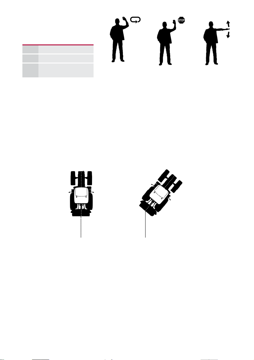
be observed by an assistant with whom the operator is in constant contact.
The assistant communicates with the operator with previously agreed signs
(see picture below).
2.2. SPECIAL SAFETY INSTRUCTIONS .
2.3. INSTRUCTIONS FOR SAFE WORK .

6
Particular attention must be paid to the correct and safe attachment of loads to the
pulling rope. The assistant must not start the attachment process until the tractor or
winch operator has been informed of his intention!
Before working, the tractor must be properly anchored with a protective winch board
which is pressed into the ground. If soft ground does not provide sufficient support
on steeper slopes or when pulling heavier loads, the tractor must be anchored with
an additional rope or chain to prevent the tractor from slipping or even tipping over!
Additional anchoring is also required if the operator cannot see the tractor.
In order to prevent accidents, load size, as well as tractor and winch capacity and
terrain characteristics (slope, soil composition, etc.) must also be taken into account
when working with a tractor and winch.
1 2 3
1Pull
2Stop
3Brake release
Ideal position Wrong - DANGEROUS
Use the lower winch pulley especially for heavier loads; this secures the risk of the
tractor tipping over. Always make sure that the rope is properly unwinding from the
pulley.
During unloading, be careful to approach the load only when the rope or brake has
been released.
Before leaving the driver's cab to operate the winch, the operator must ensure that:
the winch is lowered and securely anchored to the ground;
the tractor parking brake is activated;
the tractor is in the park position.
During uncoupling, the winch must be placed on a solid and level surface. First,
place the support legs in the correct support position, then store the PTO on the
dedicated holder.
If you cannot recognise the sign, STOP the
working process!!

7
2.
The winch may only be operated from a safe place that ensures that the machine
itself, the load, the rope, or any other object cannot hit the operator in case the
pulling rope (or any of the devices for tying and securing loads) breaks. The operator
seat of the tractor is considered to be a safe place to operate the winch, if a suitable
protective net is correctly installed between the winch and the driver's seat.
Operation of the winch from close range (up to 5 m) outside the tractor cab is only
permitted if this location is secured with appropriate protection.
Standing behind a larger tree is also considered a suitable safe place to operate the
winch from an appropriate distance.
Do not stand in the dangerous work area of the winch during operation.
2.4. DANGEROUS AREA .
The following examples are helpful for understanding individual
hazards that can also occur SIMULTANEOUSLY and
need to be taken into account.
The most common dangerous areas are:
DANGEROUS AREA:
Area within 5 m along the pulling rope.
Obstacle
1.
If the load hits another object during pulling, the vicinity of these objects
presents a dangerous area as well (e.g.: dry branches falling from the trees).
An area inside a circle with centre at an obstacle and a radius greater than the
length of the attached load.

8
3. When working with the snatch block, do not stay in the “danger triangle”
between the winch, the snatch block, and the load, where there is a danger in
case of breakage of the load belt or the snatch block.
Also, do not stay in the areas where there is a greater danger in the event of a
pulling rope breakage or any other attachment device (e.g.: hook, forestry chain,
slider).
4. The area of a potential load slip due to terrain characteristics (e.g. downhill
position, side slipping) or a pulling rope breakage (or any other load lashing
elements).

9
Do not stand under the attached load while pulling the load up or down the
slope, even if the load is secured on a tightened rope.
5. When securing a standing tree, the pulling rope must be attached to the three on
the upper 2/3 of its height, and tensioned before starting the felling process.
Position yourself with the winch outside the dangerous area, at a distance of
twice the height of the tree. If you use a snatch block to reverse the direction of
felling, the dangerous area is up to the distance of the height of a single tree.
When using the snatch block, do not stay in the “danger triangle” or other
dangerous areas!
Logging with a winch
REDIRECTED ATTACHMENT
Logging with a winch
DIRECT ATTACHMENT
L = TREE HEIGHT

10
Even if all safety precautions are followed and the winch is used according to the
instructions, some risks remain:
danger of injury due to the moving parts of the winch;
injury from flying wood particles;
human error (excessive physical exertion, psychical and psychological stress,
exhaustion, etc.).
2.5. OTHER DANGERS .
2.6. INTENDED USE .
2.7. IMPROPER USE OF THE WINCH .
The logging winch is intended for use in forestry, mainly for hauling wood. It is designed
to be used as a three-point hitch of a suitable drive machine (e.g. tractor - not stronger
than 40 kW). The winch may only be used for ground pulling work. In order to
guarantee proper use, all instructions for use must be followed.
Lifting or lowering loads with the winch is forbidden.
Any other uses of the winch than those described in the previous section are
considered incorrect, and are therefore prohibited. Tajfun accepts no liability
for any possible damage resulting from such use.

11
Mount the winch to the three point linkage system of the tractor by using three coupling pins.
The lower links of the tractor must be attached with screws to prevent the transverse
movement of the winch.
The winch is driven by a PTO shaft, which should correspond to necessary drive power of
the winch - see Technical Data - chapter 1.2.
Prior to work, lift the supporting legs of the winch
When first mounting the winch, check the P.T.O. shaft length.
Check the P.T.O. shaft length, by lifting and lowering the winch to determine the shortest
distance between the connecting shafts. In this position, the tubes of the mounted P.T.O shaft
should be approx. 20 mm shorter.
In case P.T.O. shaft is too long, it must be shortened:
Saw off steel and plastic tubes on both ends to the same length. Afterwards file down,
clean and grease the edges.
Always place the winch on the level surface. After disconnecting the winch from the tractor,
PTO shaft may remain mounted to the winch and laid on the hook.
3.CONNECTING THE WINCH
4. FUNCTION AND OPERATION OF THE WINCH
Observe all safety instructions (Chapter: 2.)!
Also follow important tips in the frames!
4.1. RELEASE THE WIRE ROPE (PERMANENT BRAKE RELEASE) (Figure 4)
By pulling the white string 1, pull the brake handle 3until it locks in place. The brake band
is released now and the drum turns freely. Now, the wire rope can be pulled off the drum.
Make sure that the wire rope pulling power is set correctly (Chapter: 4.5.).
When pulling the wire rope, use constant force, without jerking which may cause the
loosening of the wire rope on the drum and building loops.
When uncoiling the wire rope off the drum, be careful not to rip it off at the connecting point.
Model Dimensions Compatibility
PTO Shaft C Line-T 2BR +
KK560
1 3/8’’ Z6 – 1 3/8’’ Z6; LKK = 560 EGV 35 A, EGV 45 A
PTO Shaft C Line-T 4BR +
KK560
1 3/8’’ Z6 – 1 3/8’’ Z6; LKK = 560 EGV 45 AHK, EGV 55 A, EGV 55
AHK, EGV 65 A, EGV 65 AHK, EGV
65AHK ZS
PTO Shaft C Line-T 6BR +
KK560
1 3/8’’ Z6 – 1 3/8’’ Z6; LKK = 560 EGV 85 A, EGV 85 AHK, EGV 105
AHK, DGV 2X55 AHK
When using our machines, we recommend Tajfun PTO Shafts:

12
4.2. PULLING (COILING THE WIRE ROPE) (Figure 4)
By pulling the black string 2, pull the clutch handle 4and the winch begins to pull.
Always pull the clutch handle to the far end of the groove A.
Proceed as described to prevent clutch plates from slipping to increase clutch life time.
The pulling is stopped when you quickly release the clutch string 2and clutch handle 4
returns to the right position.
During the pulling, the brake handle 3is blocked in the right position. If the “permanent
brake release” (brake handle 3 was blocked in the left position) has been engaged, the
brake handle 3automatically switches to the right position, when you pull the clutch handle
4. In this position the brake prevents the load from sliding backwards when the pulling is
stopped.
WARNING:
If the brake handle 3has been previously in the left “permanent brake release” position, the
brake handle 3may suddenly switch back to the right position, when you move the clutch
handle 4.
Although the power of the PTO shaft drive remains constant, the pulling power changes.
It is useful to know that at the constant drive power, the pulling power depends on the length
of the wire rope coiled to the drum. The strongest pulling power is achieved at the first layer of
coils. By multilayer coiling the pulling power decreases progressively. The pulling power
changes in inverse proportion to the pulling speed, which is highest when the wire rope if fully
coiled.
The nominal pulling is the highest power achieved by the winch with the first layer of coils on
the drum. It is defined in the technical data section of this operating instructions and on the
type plate of each winch. By increasing the number of coil layers on the drum, the pulling
power decreases. With the full drum the pulling power comes to 50 % to 60 % of the nominal
pulling power.

13
4.3. RELEASING THE WIRE ROPE UNDER LOAD (Figure 4)
The brake prevents tied load from sliding back, when you stop the pull.
Release the stretched wire rope, by quickly pulling the white string 1of the brake handle
3.
WARNING:
When releasing the wire rope, pull the string lightly to prevent brake handle from
blocking in the “permanent brake release” position, otherwise the drum may uncoil
suddenly and the coiled wire rope may loosen.
If the wire rope on the drum gets loose, the outer coils of the wire rope get under the inner
coils at the repeated pulling, and the wire rope gets damaged quickly.
4

14
4.4. INSTALLING A NEW WIRE ROPE (Figure 5)
If the winch is mounted to a tractor, first disconnect the PTO shaft, and switch of the tractor
engine
Remove the triangular shield 2by unscrewing the screw 3
Remove the cover 6
Turn the drum to the position which will enable you to reach screw 5through the opening
By using the ring spanner No 19 partly unscrew screw 5 and pull out the old wire rope
Pass the wire rope through the upper pulley 1into the winch to the outer sidewall of the
drum. Slide the wire rope approximately 50 mm into the opening in the drum hub 4
Fasten the wire fixing screw 5
Reinstall the cover 6to close the opening and install the triangular shield 2
Coil up the wire rope onto the drum tightly (Chapter: 4.4.1.)
5

15
4.4.1. COILING THE WIRE ROPE TIGHTLY ONTO THE DRUM .
First, uncoil the wire rope completely and check its quality. Afterwards pull the black string 2
and coil up the wire rope onto the drum (Figure: 4).
Pay attention to coil the first five coils using minimum force and the rest of the wire rope using
higher force.
You can achieve this in two ways:
By pulling the load,
By fastening the wire rope to a fixed object, so that the tractor is pulled towards this object.
It is recommended to do this on a slight incline, so the tractor is pulled uphill, or by braking
slightly.
WARNING: The wire rope must always be tightly coiled up onto the drum - before
starting the work with a new winch it is necessary to uncoil the wire rope completely without
any load, check its quality and tightly coil it back onto the drum: first five coils should be coiled
by using minimum load and the rest of the wire rope using higher load!
4.4.2. WIRE ROPE QUALITY .
Only unused wire rope can be reclaimed.
Use only attested wire rope with a minimum brake point, specified in the technical data
(Chapter: 1.2.)
The wire rope must not be longer than maximum length, specified in the technical data
(Chapter: 1.2.)
WARNING:
When handling the rope, pay attention that the wire rope does not make loops when coiling or uncoiling it.
When uncoiling the wire rope off the drum, be careful not to rip it off at the connecting point.
4.4.3. WIRE ROPE UNCOILING (Figure: 6)
Correct Incorrect
6

16
4.5. SETTING THE WIRE ROPE RELEASE POWER (Figure: 7)
The wire rope release power must be set correctly, so the drum stops immediately after
releasing the wire rope. This prevents the wire rope on the drum from releasing by itself.
Wire rope release power setting procedure:
Release the safety nut 2
Screw or unscrew the screw 1to influence the brake band 3through the leaf spring 4.
By screwing or unscrewing the screw 1, the wire rope release power increases or
decreases
Screw the counter nut 2
(Magnification C Figure 4)
7

17
4.6. SETTING THE WINCH PULLING POWER (Figure 8)
Each winch is factory set to its maximum pulling power which is also specified on the winch
type plate. Increasing of the pulling power over this value is not allowed. After the pulling
power of the winch decreases due to the wear of clutch linings, the clutch must be readjusted.
Pulling power setting procedure:
Disconnect the PTO shaft and shut down the tractor.
Use the spanner No 30 to release the safety plug 4on the drum axis by turning it to the
left.
Use the spanner No 50 to turn the nut 3M40 to the right so that you can pull the string 1,
by using force “F” to move the clutch handle 2to the end of the groove A.
Screw the safety plug 4tightly to prevent the nut M40 from releasing.
It is important to tighten the nut M40 only so tight, that you can still pull the clutch
handle 2 to the end of the groove A using the force “F” and reach the nominal pulling
power (See Chapter: 4.2.)!
By proper adjustment of nut M40, set the nominal pulling power.
If the nut M40 is set too tightly, you cannot move the handle 2to the end of the groove and
pulling power decreases. If the nut M40 is set too loose, it causes excessive deviation of
the drum, which can cause falling of the clutch plates off it’s pins. If this happens, the
whole drum must be dismantled.
»F«
35 A 250 N
8

18
4.7. SETTING THE WINCH BRAKE POWER (Figure: 9)
The brake band is s factory set to the brake power which is 25 % higher than the nominal
pulling power of the winch. The brake power changes due to the wear of the brake band lining
and has to be readjusted periodically. Properly adjusted brake band prevents the load from
sliding backwards when the brake handle is the right position and allows pulling the wire rope
out of the winch, when the brake handle is in the »permanent brake release« position.
Set the brake power by screwing or unscrewing the nut 8. The brake power is adjusted
properly when the spring length is B. (Distance »B« is only an orientation point for
approximate setting of brake power. Exact setting can only be achieved by using a
measuring instrument).
By screwing the nut 8from its starting position towards the pressure spring 9, you increase
the brake power and vice versa.
Checking the correct position of the handle 4:
Push the clutch handle 3to the left, to move the upper bar 2 of the blocking mechanism 1
to the left and switch the brake handle 4in the »permanent brake release« position.
Check if the groove on the lower bar of the blocking mechanism Ais aligned with the outer
edge of upper stop plate 1. If this is not the case, adjust the position of the groove by
screwing or unscrewing the nuts 5and 7. Screw the nuts tightly afterwards-magnification A
Release the clutch handle 3. The distance between nuts 7and 8 is C.
Warning: If the brake handle 3has been previously in the left “permanent brake release”
position, the brake handle 3may suddenly switch back to the right position, when you move
the clutch handle 4.
EGV 35 A
B 65 mm
C 18 mm
9

19
4.8. CHECKING AND TIGHTENING THE DRIVE CHAIN (Figure 10)
During the operation and under the load, the drive chain stretches, therefore the operator
must check and readjust the chain periodically to prevent excessive wear of the whole chain
drive. The chain must not be set to tight and chain slack should be set to ± 3 mm. Check the
tightness of the chain by hand, pushing the chain between the chain wheels.
Lubricate the chain using special chain lubrication spray.
Procedure :
If the winch is connected to the tractor, shut down the tractor and disconnect the PTO shaft
Unscrew the screw 3and remove the chain cover 4 by pushing it upwards.
Loosen both nuts 2by approximately one turn
Tighten the drive chain, by screwing the nut on the tightening screw 1until you reach the
desired chain slack: ± 3 mm
Screw the nuts 2tightly
Install the chain cover and fasten it using the screw 3.
10

20
5. SERVICING AND MAINTAINING THE WINCH
Regular and proper maintenance is necessary for trouble free and long-life operation of the
winch.
5.1. TROUBLESHOOTING .
PROBLEM : POSSIBLE CAUSES: ACTION:
The winch pulling
power is low
Too much wire rope on the drum (Chapter: 1.2.)
Incorrectly adjusted clutch Set the pulling power according to
the instructions (Chapter: 4.6.)
Greasy clutch plates
(improper chain drive lubrication)
Worn out clutch plates
Fault in the switching mechanism Check the operation of the switching
mechanism (Chapter: 4.7.)
Damaged driving component of the
winch Replace the damaged parts
The brake does not
function
Incorrectly adjusted brake Set the brake power (Chapter: 4.5)
Brake band lining is greasy Clean the brake band lining and the drum
surface
Damaged brake mechanism Replace the damaged parts
Worn out brake band Replace the brake band
Wire rope is hard to pull
out
Incorrectly set wire rope release
power
Set the wire rope release power
according to the instructions (Chapter:
4.5.)
Damaged wire rope Replace the wire rope (Chapter: 4.4.)
Damaged brake band Replace the brake band
The winch is pulling
when the clutch is
disengaged
Incorrectly adjusted clutch Check the pulling power setting,
according to the instructions (Chapter:
4.6. )
Damaged drum Replace the drum
Damaged clutch plates Replace the clutch plate
Clean the surface of the clutch plates or
replace the clutch plates
More demanding procedures must be performed by a qualified technical service, only.
The machine is functionally and safety tested. In case of breakdown it is necessary to use
only original spare parts to ensure flawless and safe operation. The customer looses all claims
of warranty if non-original spare parts are used, if the winch is not maintained according to
maintenance plan, if repairs are performed unprofessionally or by unqualified person.
Other manuals for EGV 35 A
1
Table of contents
Other Tajfun Industrial Equipment manuals