Tajfun EGV 45A User manual

1
Ver.: 2.6 10/2009 - ENG
OPERATING INSTRUCTIONS
LOGGING WINCH
Please read operating instructions carefully before installing and
using the logging winch.
45A 55A 65A 85A
EGV 45A,
EGV 55A, EGV 55A 1.8M,
EGV 65A, EGV 65A 1.8M, EGV 65A 2.05M,
EGV 85A, EGV 85A 1.95M, EGV 85A 2.05M

2
Dear Customer,
By purchasing our winch, you obtained the equipment which will provide you with great help in
your work. To make operating the machine as safe and pleasant as possible, please carefully
read this operating instructions and follow the safety and maintenance guidelines.
We would like to thank you for your trust and wish you great satisfaction in your work.
1. GENERAL
Chapter: Page:
1.3. TECHNICAL DATA 3
2. SAFETY INSTRUCTIONS 4
3. CONNECTING THE WINCH 8
4. FUNCTION AND OPERATION OF THE WINCH 8
4.1. RELEASING THE WIRE ROPE (PERMANENT BRAKE RELEASE) 8
4.2. PULLING (COILING THE WIRE ROPE) 9
4.3. RELEASING THE WIRE ROPE UNDER LOAD 10
4.4. INSTALLING A NEW WIRE ROPE 11
4.4.1. COILING THE WIRE ROPE TIGHTLY ONTO THE DRUM 12
4.4.2. WIRE ROPE QUALITY 12
4.4.3. COILING THE WIRE ROPE 12
4.5. SETTING THE WIRE ROPE RELEASE POWER 13
4.6. SETTING THE WINCH PULLING POWER 13
4.7. SETTING THE WINCH BRAKE POWER 15
4.8. CHECKING AND TIGHTENING THE DRIVE CHAIN 16
5. MAINTENANCE 18
5.1. TROUBLESHOOTING 18
5.2. MAINTENANCE PLAN 19
5.3. CONSEQUENCES OF MACHINE OVERLOAD AND MISUSE 20
5.4. SPARE PARTS ORDERING 20
1. GENERAL 2
1.1. TABLE OF CONTENTS 2
1.2. APPLICATION 3
1.4. TYPE PLATE 3
1.1. TABLE OF CONTENTS .

3
1.3. TECHNICAL DATA .
1.2. APPLICATION .
Logging winch is intended for the agriculture use, especially for pulling the wood. The winch is
constructed as a three point connecting piece of the suitable driving machinery. The winch
may be used for pulling loads on the ground, only. This operating instructions also
describe proper use and maintenance of the winch. Any other application of the machine is
considered as unintended use and the manufacturer Tajfun does not take any responsibility
for eventual damages caused by such application.
EGV 45 A EGV 55 A EGV 65 A EGV 85 A
Nominal Pulling Power (max) 45 kN 55 kN 65 kN 85 kN
Pulling Power at a Full Drum 22.4 kN 27.9 kN 32,8 kN 39.5 kN
Brake Power 56 kN 69 kN 81 kN 106 kN
Pulling Speed (at 540 rpm -
PTO shaft) (0.54 - 1.08) m/s (0.54 - 1.07) m/s (0.50 - 0,.9) m/s (0.51 - 1.10) m/s
Gear Ratio 1 : 8.89 1 : 8.89 1 : 10.80 1 : 10.67
Required Drive Power (15 - 37) kW
(20 - 50) PS
(25 - 52) kW
(35 - 70) PS
(37 - 66) kW
(50 - 90) PS
(52 - 100) kW
(70 - 135) PS
Wire Rope Length - Drum
Capacity
9 / 125 m,
10 / 94 m,
11 / 78 m,
12 / 61 m.
10 / 95 m,
11 / 78 m,
12 / 61 m,
13 / 56 m.
11 / 140 m,
∅
12 / 118 m,
13 / 89 m,
14 / 78 m.
13 / 110 m,
14 / 106 m,
15 / 86 m.
Wire Rope Min. Brake Point
(FSmin) 90 kN 110 kN 130 kN 170 kN
Width 1,400 mm 1,500 mm 1,660 mm 1,800 mm
Length 525 mm 565 mm 670 mm 680 mm
Height without protective net 1,260 mm 1,510 mm 1,660 mm 1,710 mm
Height with protective net 2,300 mm 2,300 mm 2,300 mm 2,300 mm
Transport Height 1,361 mm 1,600 mm 1,729 mm 1,780 mm
Max. Operating Noise 70 dB (A) 70 dB (A) 70 dB (A) 70 dB (A)
Weight 330 kg 345 kg 515 kg 570 kg
1.4. TYPE PLATE .
a Year of Manufacture
b Serial Number
c Wire Rope Min. Break Point
a
b
c

4
2. SAFETY INSTRUCTIONS
Operating the winch is demanding and dangerous, therefore an absolute concentration and
caution are essential. For effective and safe operation please observe the following
guidelines:
Take safety precautions! Observe all safety guidelines and carefully read the
operating instructions.
Winch operation and maintenance is allowed to qualified persons older than 18 years
of age, only! User personal protective equipment (helmet, gloves, forestry boots).
User personal protective equipment (helmet, gloves, forestry boots).
Never work alone in the forest! If unavoidable, use radio communication device.
Check the operation of the winch prior to any use, at least once every working day.
Any deficiency should be eliminated immediately. The winch must be inspected by
an expert at least once a year.
Disconnect the winch drive, when performing repair or maintenance work. Besides
disconnecting the tractor PTO-shaft, also shut down the tractor engine.
All protective parts of the winch (safety nets, covers, ...) must be in place during the
operation. Any modification of these protective parts is not permitted!
Use only appropriate winching devices and equipment, suitable to the winch pulling
power (forestry chains, hooks, portable pulleys, belts, …).
Wire ropes must have sufficient strength and meet technical data requirements of the
winch (See type plate). Minimal break point of the wire rope or other pulling means
(chain…) must be at least twice as high as the maximum winch pulling power.
Replace the damaged wire rope as soon as possible!
Use wire ropes of appropriate length! The permitted wire rope length is set by fully
coiling the wire rope onto the drum. The difference between upper layer of the coiling
and the edge of the drum should not be lower than twice the diameter of the wire
rope.
Before the beginning of work, the operator has to make sure the work can be
preformed safely.
Winch operator has to pay attention, that the wire rope does not uncoil completely
under the load and that at least five coils of the rope remain on the drum (except in
case of emergency).
The wire rope must be coiled to the drum tightly (Chapter 4.4.1.).

5
The operator should control the winch from the safe area (5 m away from the winch).
The machine, load, wire rope or other objects which can get thrown towards the
winch in case of breakage of wire rope or other pulling means can pose a danger to
the operator. Tractor cabin is also considered as a safe operating spot, in case the
safety net is installed properly between the driver’s seat and the winch.
Winch operation from a close distance (up to 5 m) and operation outside of the
tractor cabin is permitted only if the area is secured with a dedicated protection.
Suitable and safe area for winch operation should be in an appropriate distance from
the tractor and the winch, for example behind the three.
In case you operate the winch using the remote control and walk besides the log
being pulled, you have to stay near the wire rope connecting point.
When pulling logs, the operator should follow the load parallel, near the wire rope
connecting point. When pulling branches and tree tops, the operator may follow the
load diagonally, behind the load (Figure 2a).
The winch operator must constantly observe the load being pulled. If the pulling
distance is not visible from his position, an assistant in constant contact with the
operator must observe the load. The winch operator and assistant communicate with
previously agreed signs (Figure: 2b).
Special attention should be paid to proper and safe fastening of the load. The
assistant should not start with the fastening procedure, until he or she notifies the
tractor operator!
When working with wire rope, do not stay in the area between the load and the winch
and in the dangerous triangle between the winch, pulley and the load (Figure: 2c).
1 2 3
1 - Pull
2 - Stop
3 - Wire Release
Unrecognized sign means STOP!!
2b
2a
Dangerous area
Obstacle*
Safe operating spot when
using remote control
* In case the obstacle is a tree, the operator has also
consider possible danger from falling dry branches.

6
nevarni trikotnik
odtrgani šk ripec
mesto pri trditve škripca
vlečna vrv
2c
When pulling the logs on the steep slope, do not stay under the load, even if the
load is standing still on the stretched wire rope.
When pulling the tree which is still standing, tighten the wire rope before the
beginning of felling. Position yourself and the winch outside the dangerous area in
the distance twice the tree height. In case you use the pulley to alter the pulling
direction, the dangerous area is within a radius of single tree height (Figure: 2d).
When using the pulley, do not stay in the dangerous triangle!
2d
2L
Dangerous Triangle
Torn Pulley
Pulley connecting spot
Wire Rope

7
Use the lower pulley on the winch to prevent any possible tractor turnover,
especially when pulling heavier loads. Pay special attention that the wire rope is
aligned properly in the pulley.
When releasing the loads, do not approach the load until the wire rope is loose or the
brake is released.
When using the tractor with hydrodynamic drive, the operator must, before leaving
the tractor cabin, make sure that:
- supporting legs are lowered and the winch is lowered to the ground and
anchored
- tractor brake is activated
- tractor transmission is in the neutral position.
When disconnecting the winch, it is necessary to place the winch on the hard and
level surface. First, the supporting legs must be set in the supporting position and
PTO shaft must be placed in the dedicated holder.
Observe traffic regulations! In case you drive on public roads, also observe all
current regulations for designation of tractor equipment which is connected to the
back of the tractor.
The connector on the winch is intended as an implement and should not be used on
public roads.
Tractor which powers the winch should have sufficient tire threat depth: at least 40 %
left, otherwise installation of tire chains is necessary. Permanent use of tire chains is
required when working in the snow or ice in winter conditions.
Before beginning of the work, the tractor must be anchored well using the winch
board. In case the soft ground does not give enough support, the tractor should be
anchored using additional wire rope or chain to prevent possibility of slippage or
even tractor turnover, especially when working on steeper slopes or when pulling
heavier loads!
The size of the load and pulling speed should be adjusted to the tractor strength and
capability as well as to the inclination of the slope and ground composition to
prevent possibility of turnover and to keep maneuverability and braking efficiency.
2e
Wrong - DANGEROUS Ideal position

8
Mount the winch to the three point linkage system of the tractor by using three coupling pins.
The lower links of the tractor must be attached with screws to prevent the transverse
movement of the winch.
The winch is driven by a PTO shaft, which should correspond to necessary drive power of
the winch - see Technical Data - chapter 1.3.
Prior to work, lift the supporting legs of the winch
When first mounting the winch, check the P.T.O. shaft length.
Check the P.T.O. shaft length, by lifting and lowering the winch to determine the shortest
distance between the connecting shafts. In this position the tubes of the mounted P.T.O shaft
should be approx. 20 mm shorter.
In case P.T.O. shaft is too long, it must be shortened:
Saw off steel and plastic tubes on both ends to the same length. Afterwards file down,
clean and grease the edges.
Always place the winch on the level surface. After disconnecting the winch from the tractor,
PTO shaft may remain mounted to the winch and laid on the hook.
3. CONNECTING THE WINCH
4. FUNCTION AND OPERATION OF THE WINCH
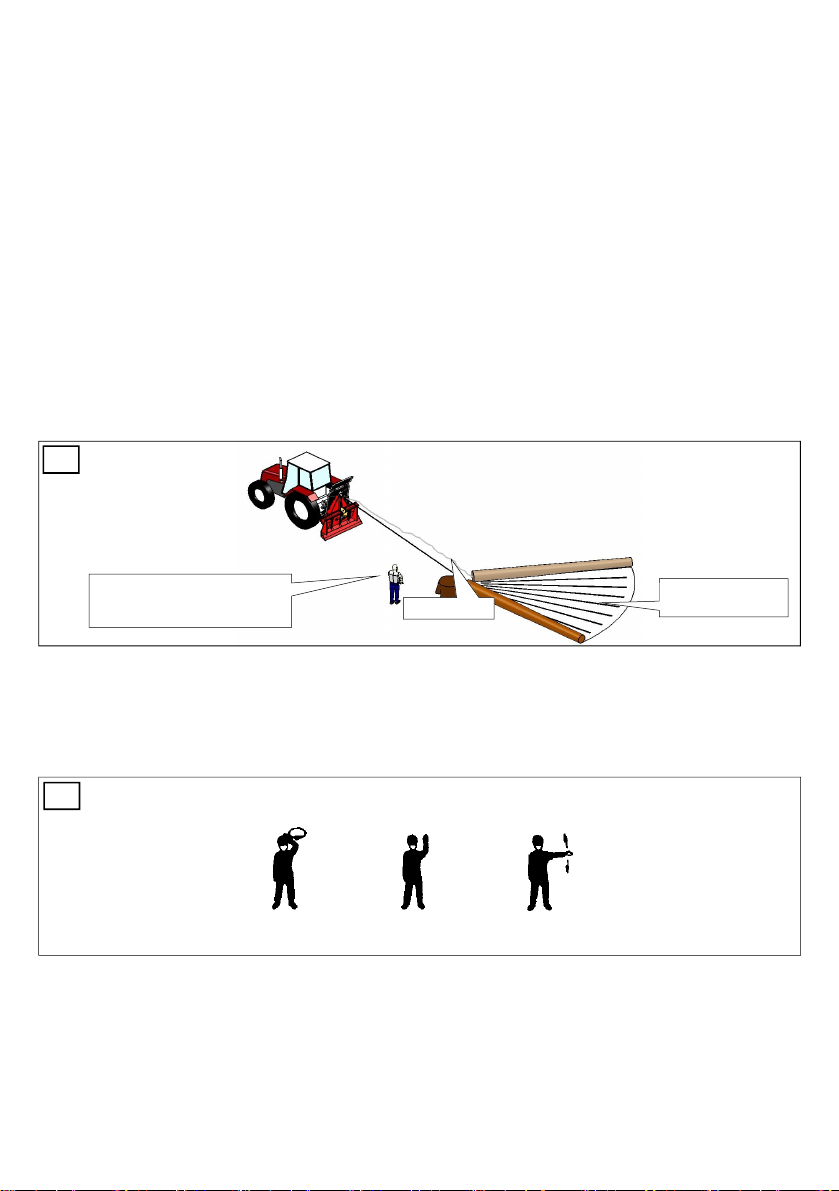
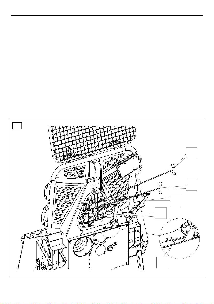
4.1. RELEASE THE WIRE ROPE (PERMANENT BRAKE RELEASE) (Figure 4)
By pulling the white string 21, pull the brake handle 20 until it locks in place. The brake
band is released now and the drum turns freely. Now, the wire rope can be pulled off the
drum. Make sure that the wire rope pulling power is set correctly (Chapter: 4.5.).
When pulling the wire rope use constant force, without jerking which may cause the loosening
of the wire rope on the drum and building loops.
When uncoiling the wire rope off the drum, be careful not to rip it off at the connecting point.
Observe all safety instructions (Chapter: 2.)!
Also follow important tips in the frames!
When using our machines, we recommend Tajfun PTO Shafts:
Model Dimensions Compatibility
PTO Shaft C Line-T 2BR +
KK560
1 3/8’’ Z6 – 1 3/8’’ Z6; LKK = 560 EGV 35 A, EGV 45 A
PTO Shaft C Line-T 4BR +
KK560
1 3/8’’ Z6 – 1 3/8’’ Z6; LKK = 560 EGV 45 AHK, EGV 55 A, EGV 55
AHK, EGV 65 A, EGV 65 AHK, EGV
65AHK ZS
PTO Shaft C Line-T 6BR +
KK560
1 3/8’’ Z6 – 1 3/8’’ Z6; LKK = 560 EGV 85 A, EGV 85 AHK, EGV 105
AHK, DGV 2X55 AHK

9
4.2. PULLING ( COILING THE WIRE ROPE ) (Figure 4 )
By pulling the black string 11, pull the clutch handle 10 and the winch begins to pull.
Always pull the clutch handle to the far end of the groove H.
Proceed as described to prevent clutch plates from slipping to increase clutch life time.
The pulling is stopped when you quickly release the clutch string 11 and clutch handle
10 returns to the right position.
During the pulling, the brake handle 20 is blocked in the right position. If the “permanent
brake release” (brake handle 20 was blocked in the left position) has been engaged, the
brake handle 20 automatically switches to the right position, when you pull the clutch
handle 10. In this position the brake prevents the load from sliding backwards when the
pulling is stopped.
WARNING:
If the brake handle 20 has been previously in the left “permanent brake release” position, the
brake handle 20 may suddenly switch back to the right position, when you move the clutch
handle 10.
Although the power of the PTO shaft drive remains constant, the pulling power changes.
It is useful to know that at the constant drive power, the pulling power depends on the length
of the wire rope coiled to the drum. The strongest pulling power is achieved at the first layer of
coils. By multilayer coiling the pulling power decreases progressively. The pulling power
changes in inverse proportion to the pulling speed, which is highest when the wire rope if fully
coiled.
The nominal pulling is the highest power achieved by the winch with the first layer of coils on
the drum. It is defined in the technical data section of this operating instructions and on the
type plate of each winch. By increasing the number of coil layers on the drum, the pulling
power decreases. With the full drum the pulling power comes to 50 % to 60 % of the nominal
pulling power.

10
4.3. RELEASING THE WIRE ROPE UNDER LOAD (Figure 4)
The brake prevents tied load from sliding back, when you stop the pull.
Release the stretched wire rope, by quickly pulling the white string 21 of the brake handle
20.
WARNING:
When releasing the wire rope, pull the string lightly to prevent brake handle from
blocking in the “permanent brake release” position, otherwise the drum may uncoil
suddenly and the coiled wire rope may loosen.
If the wire rope on the drum gets loose, the outer coils of the wire rope get under the inner
coils at the repeated pulling, and the wire rope gets damaged quickly.
4
H
21
20
11
10

11
4.4. INSTALLING A NEW WIRE ROPE (Figure 5)
If the winch is mounted to a tractor, first disconnect the PTO shaft, and switch of the tractor
engine
Remove the triangular shield 2 by unscrewing the screw 3
Remove the cover 6
Turn the drum to the position which will enable you to reach screw 5 through the opening
By using the ring spanner No 19 partly unscrew screw 5 and pull out the old wire rope
Pass the wire rope through the upper pulley 1 into the winch to the outer sidewall of the
drum. Slide the wire rope approximately 50 mm into the opening in the drum hub 4
Fasten the wire fixing screw 5
Reinstall the cover 6 to close the opening and install the triangular shield 2
Coil up the wire rope onto the drum tightly (Chapter: 4.4.1.)
5

12
4.4.1. COILING THE WIRE ROPE TIGHTLY ONTO THE DRUM .
First, uncoil the wire rope completely and check its quality. Afterwards pull the black string 11
and coil up the wire rope onto the drum (Figure: 4).
Pay attention to coil the first five coils using minimum force and the rest of the wire rope using
higher force.
You can achieve this in two ways:
By pulling the load;
By fastening the wire rope to a fixed object, so that the tractor is pulled towards this object.
It is recommended to do this on a slight incline, so the tractor is pulled uphill, or by braking
slightly.
WARNING: The wire rope must always be tightly coiled up onto the drum - before
starting the work with a new winch it is necessary to uncoil the wire rope completely without
any load, check its quality and tightly coil it back onto the drum: first five coils should be coiled
by using minimum load and the rest of the wire rope using higher load!
4.4.2. WIRE ROPE QUALITY .
Only unused wire rope can be reclaimed.
Use only attested wire rope with a minimum brake point, specified in the technical data
(Chapter: 1.3.).
The wire rope must not be longer than maximum length, specified in the technical data
(Chapter: 1.3.).
WARNING:
When handling the rope, pay attention that the wire rope does not make loops when coiling or uncoiling it.
When uncoiling the wire rope off the drum, be careful not to rip it off at the connecting point.
Correct Incorrect
6
4.4.3. WIRE ROPE UNCOILING (Figure: 6)

13
4.5. SETTING THE WIRE ROPE RELEASE POWER (Figure: 9)
The wire rope release power must be set correctly, so the drum stops immediately after
releasing the wire rope. This prevents the wire rope on the drum from releasing by itself.
Set the wire rope release power using the wing nut 41 (Figure: 9).
By screwing or unscrewing the wing nut 41, the wire rope release power increases or
decreases.
4.6. SETTING THE WINCH PULLING POWER (Figure: 8)
Each winch is factory set to its maximum pulling power, which is also specified on the winch
type plate. Increasing of the pulling power over this value is not allowed. After the pulling
power of the winch decreases due to the wear of clutch linings, the clutch must be readjusted.
Pulling power setting procedure:
Disconnect the PTO shaft and shut down the tractor.
Use the spanned No 13 to unscrew the nut 33 and remove the safety pin 31.
Use the spanner No 50 (45A, 55A) / No 60 (65A, 85A) to turn the nut 30 to the right so that
you can pull the string 11 using force “F” to move the clutch handle 10 to the end of the
groove H.
Install the safety pin 31 and tighten the screw 33, to prevent the nut 30 from releasing.
It is important to tighten the nut 30 only so tight, that you can still pull the clutch
handle 10 to the end of the groove H using the force “F” and reach the nominal pulling
power (See Chapter: 4.2.)!
By proper adjustment of nut 30, set the nominal pulling power.
If the nut 30 is set too tightly, you cannot move the handle 10 to the end of the groove and
pulling power decreases. If the nut 30 is set too loose, it causes excessive deviation of the
drum, which can cause falling of the clutch plates off it’s pins. If this happens, the whole
drum must be dismantled.

14
8
33
H
11
10
31
30
»F«
45 A 270 N
55 A 270 N
65 A 220 N
85 A 260 N

15
4.7. SETTING THE WINCH BRAKE POWER (Figure: 9)
The brake band is s factory set to the brake power which is 25 % higher than the nominal
pulling power of the winch. The brake power changes due to the wear of the brake band lining
and has to be readjusted periodically. Properly adjusted brake band prevents the load from
sliding backwards when the brake handle is the right position and allows pulling the wire rope
out of the winch, when the brake handle is in the »permanent brake release« position.
Set the brake power by screwing or unscrewing the drawn cup 42, to reach the distance L.
(Distance »L« is only an orientation point for approximate setting of brake power. Exact set-
ting can only be achieved by using a measuring instrument).
By screwing the drawn cup 42 from its starting position, you increase the brake power, and
vice versa.
Using spanner No 19 screw the counter nut 43 to prevent unscrewing of the drawn cup 42.
Setting the initial position:
Remove the triangular shield 3 (Fig.: 5) by unscrewing the screw 2 (Fig.: 5).
Push the clutch handle 3 to the left and release the clutch handle 10 again. The clutch
handle is now in the right position.
Check if the groove on the lower bar of the blocking mechanism M is aligned with the outer
edge of the chassis 45. If this is not the case, adjust the position of the groove by screwing
or unscrewing the drawn cup 42 and counter nut 43. Screw the counter nut tightly
afterwards.
WARNING:
If the brake handle 20 has been previously in the left “permanent brake release” position, the
brake handle 20 may suddenly switch back to the right position, when you move the clutch
handle 10.
9
41 42 43
45 M
EGV 45A EGV 55A
L 52 mm 52 mm
EGV 65A
52 mm
EGV 85A
50 mm

16
4.8. CHECKING AND TIGHTENING THE DRIVE CHAIN (Figure 10)
During the operation and under the load, the drive chain stretches, therefore the operator
must check and readjust the chain periodically to prevent excessive wear of the whole chain
drive. The chain must not be set to tight and chain slack should be set 1 to 3 mm. Shorther
chain should allow ±1 mm slack and longer chain ±3 mm. Check the tightness of the chain by
hand, pushing the chain between the chain wheels.
Lubricate the chain using special chain lubrication spray.

17
Procedure:
If the winch is connected to the tractor, shut down the tractor and disconnect the PTO
shaft.
Unscrew the screw 3 and remove the chain cover 4 by pushing it upwards.
Loosen both screws 5 by approximately one turn, to move the drive chassis 8.
First tighten the shorter chain 2 using the tensioning screw 7 and counter nut 6. Screw the
counter nut tightly, afterwards. The slack of the shorter chain should be ±1 mm.
Tighten the longer chain 9 by screwing the nut on the tightening screw 1 until you reach
the desired chain slack: ±3 mm.
Screw the screws 5 tightly.
Install the chain cover 4 and fasten it using the screw 3.
10

18
5. SERVICING AND MAINTAINING THE WINCH
Regular and proper maintenance is necessary for trouble free and long-life operation of the
winch.
5.1. TROUBLESHOOTING .
PROBLEM: POSSIBLE CAUSES: ACTION:
The winch pulling
power is low
Too much wire rope on the drum (Chapter: 1.3.)
Incorrectly adjusted clutch Set the pulling power according to
the instructions (Chapter: 4.6.)
Greasy clutch plates
(improper chain drive lubrication)
Worn out clutch plates
Fault in the switching mechanism Check the operation of the switching
mechanism (Chapter: 4.7.)
Damaged driving component of the
winch Replace the damaged parts
The brake does not
function
Incorrectly adjusted brake Set the brake power (Chapter: 4.5.)
Brake band lining is greasy Clean the brake band lining and the drum
surface
Damaged brake mechanism Replace the damaged parts
Worn out brake band Replace the brake band
Wire rope is hard to
pull out
Incorrectly set wire rope release
power
Set the wire rope release power
according to the instructions (Chapter:
4.5.)
Damaged wire rope Replace the wire rope (Chapter: 4.4.)
Damaged brake band Replace the brake band
The winch is pulling
when the clutch is
disengaged
Incorrectly adjusted clutch Check the pulling power setting,
according to the instructions (Chapter:
4.6.)
Damaged drum Replace the drum
Damaged clutch plates Replace the clutch plate
Clean the surface of the clutch plates or
replace the clutch plates
More demanding procedures must be performed by a qualified technical service, only.
The machine is functionally and safety tested. In case of breakdown it is necessary to use
only original spare parts to ensure flawless and safe operation. The customer looses all claims
of warranty if non-original spare parts are used, if the winch is not maintained according to
maintenance plan, if repairs are performed unprofessionally or by unqualified person.

19
5.2. MAINTENANCE PLAN .
Before starting any operation, the winch must be checked visually and functionally:
All nuts and screws must be screwed tightly
There should be no mechanical damages
All safety devices are installed on the connecting parts of the winch
The PTO shaft is correctly connected and secured by the safety chain
The bottom links of the tractor are correctly fixed and prevent the winch from moving
horizontally
The clutch is operating properly
Brake band is operating properly
The wire rope release power is set correctly
Remove all faults and deficiencies before staring the operation
WHAT to do? WHEN? HOW?
Release the rope and coil it tightly onto the
drum,
Check if the wire rope is undamaged,
Check if the wire rope is fixed properly
When using a new winch
When the wire rope is loose on the
drum
Visually
Ch.: 4.4.1.
Checking and tightening of the chain Every 48 hours of operation Ch.: 4.8.
Clutch plates replacement When necessary
Brake band replacement When necessary
Lubrication
(Figure:11)
A Cable pulley’s bearing No lubrication
B Drive chain Every 48 hours of operation Chain
lubrication
spray
C The upper and lower pulley
beds and other sliding
elements.
At least once a month Lithium
grease
oil
D Wire rope Once a month Lithium
grease
E Small pulleys’ bearings Before setting the pulling power Oil, spray
Cleaning the framework interior Every 100 hours of operation or more
frequently in case of harsh operating
conditions

20
5.3. CONSEQUENCES OF MACHINE OVERLOAD AND MISUSE .
Burnt clutch plates
Burnt brake band
Damaged brake mechanism
Torn chain
Broken pulley or pulley bearing
Damaged cardan shaft-s housing
Damaged cardan shaf-s or chain sprockets
Bent framework (couplings, safety elements, drive carrying elements, pulleys, …)
Torn "new" wire rope or linking chain of appropriate strength
Bent drum axle
Torn brake band
When ordering spare parts it is necessary to provide the following information:
Winch type, serial number and year of manufacture;
catalogue number, name and quantity of the spare part; Exact customer’s address.
The manufacturer warrants the availability of any spare parts and service for the period of 10
years following the purchase of the machine.
11
5.4. SPARE PARTS ORDERING .
This manual suits for next models
8
Table of contents
Popular Winch manuals by other brands

DK2
DK2 Warrior Spartan 1200 Assembly & operating instructions

Harken
Harken UniPower Radial Installation and maintenance manual

TORSO WINCH
TORSO WINCH CW02V12 Installation and operating instructions

MZ electronic
MZ electronic Italwinch Arado Installation and user manual

Comeup
Comeup CAP-9s manual

Ingersoll-Rand
Ingersoll-Rand Man Rider LS2-150RLP-L E Series Product Maintenance Information