Takara Belmont RS User manual

1
If RS SWING is installed after ignoring this symbol, "there is the risk of light or moderate injury or physical
damage".
●The precautions listed here are to ensure that RS SWING can be installed safely, and to prevent any
danger or risk to the person installing RS SWING or those around them. All of these precautions are
important for safety. Takara Belmont is not responsible for any damage or risk to the person installing RS SWING
or those around them due to accidents if RS SWING is installed without adhering to the precautions.
To the customers
• Customers must ask proffessional to install RS SWING.
• Customers must not install RS SWING by themselves.
• Customers must store these instructions in
a safe place so as not to lose them.
To the installer
• The instructions should be thoroughly read
and understood before installation to ensure
that RS SWING is installed correctly.
• After installation, give these instructions to the customer.
* The actual shape of RS SWING and the images and
dimensions listed in these instructions may be modified
and are subject to change without notice.
Caution
Contents
2
3
4
5
8
12
13
14
January 2016
Varsion 1
Before installation
Usage conditions
Content of packaging
Installation of Main Unit
Assembled
Overall Layout Diagram
Unit fixing position and Plumbing Layout
After installation
RSSWING
InstallationInstructions
■AY-P004〜P011 / S033X

2
■Floor surface
○Ensure that the material or finishing of the floor surface is waterproof or has a waterproof coating applied.
○This product weighs There are maximum 55㎏. Please refer to the sufficient reinforcement work on the installation floor portion.
○Always ensure that the floor surface is horizontally level.
○Ensure that the floor surface is smooth and free from bumps around the attachment areas.
○Pipe risers
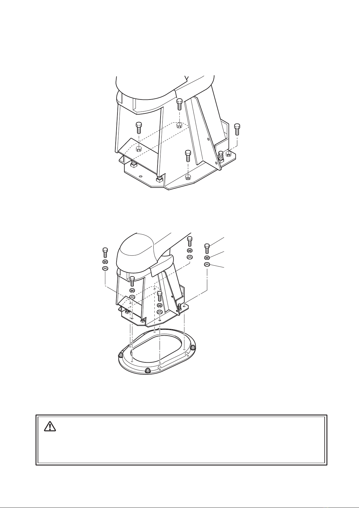
○If the floor surface is tiled, cracks may occur when fastening the bolts during installation of the RS SWING main body.
If this looks likely to happen, use the main body attachment diagram and template as a reference and change the material
of the attachment area that is in contact with the floor to another such as plywood or mortar.
○The following levels of strength are required for the floor surface.
○Be sure to take the necessary precautions to prepare for and prevent possible water leakage.
○Use waterproof flooring materials.
○When installing the product on the 2nd floor or higher, be sure to observe waterproofing (waterproofing works,
installing a pan made of stainless panel, etc. or installing water leakage sensor.).
○Be sure to cover an opening of raised plumbing and a connection of pipes by caulking material, etc.
■Request measures to prevent water leakage under the floor and downstairs
Hot water / water supply
Drainage
Rc 1/2"; pipe risers from floor; rise dimensions: hot water 50 mm; water 50 mm
VU40/VP40; pipe risers from floor; rise dimensions: 60 mm
Wooden floor
Mortar floor Mortar thickness of 50 mm or more
Special floor (stone finish) A foundation with levels of strength listed above around the installation areas is required.
Plywood thickness of 30 mm or more (two 15 mm sheets joined together)
■Installation of pipes
The following are important points to adhere during the installation of pipes. Read through
the details carefully and ensure that the pipes are installed correctly.
○This product is designed for indoor installation. Always install this product indoors.
■”Precautions during installation of pipes”
○Do not use pipes made of materials that may introduce rust for the water supply pipe. In general, VP pipes or other materials
specified by regulations in that particular region, are recommended for installation.
○In general, Type L deoxidized copper pipes are recommended for hot water pipes.
○In general, the same diameter and same pressure is recommended for hot water pipes and water supply pipes.
○Always use a reamer to deburr the ends of cut pipes.
○Avoid using inverted U-shaped pipes (siphon) as these can cause air to become trapped.
○Always connect hot water and water supply pipes after removing all contaminants such as dirt, sand and oil.
Failure to follow this instruction may cause problem.
○Ensure that the drain pipe is installed at a gradient of 1/50 for a diameter of φ75 or less, or 1/100 for a diameter of φ75
or more.
○Do not connect the hot water and water supply pipes in reverse.
Connecting pipes in reverse will mean the temperature of water cannot be controlled properly by the water faucet,
which can cause problems including burns.
○Ensure that the hot water pipe from boiler is only run over a short distance so as to minimize resistance.
Longer pipe can cause fluctuations in temperature and poor hot water delivery.
○Boiler pipes
・ In general, the same diameter and same pressure is recommended for main hot water pipe and main water supply pipe.
・ Ask professional to install boiler.
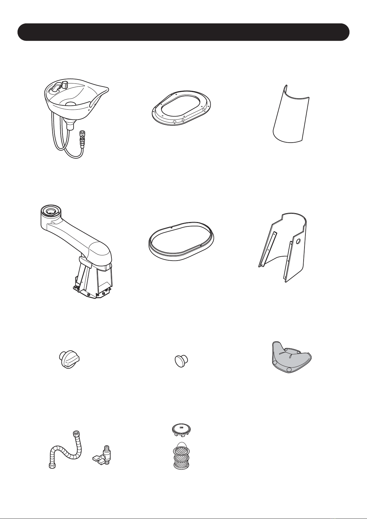
○Product comes with hair catchers installed. Handle it with care.
○Always wrap pipes with lagging material after installation is complete.
○After connecting the pipes and executing water flow test, clean the filters and showerhead.
Before installation

3
使用条件
Usage conditions
■ Hot water supply and water supply conditions
・Use a pressure between 0.1 and 0.4 MPa (1 to 4 kgf/cm2). If multiple RS SWING are used,
ensure that the pressure does not drop below 0.1 MPa (1 kgf/cm2).
・Set the water supply pressure ≧hot water supply pressure.
・Set the difference between the hot water supply pressure and water supply pressure to within
0.2 MPa (2 kgf/cm2).
・Set the hot water temperature to 80℃or less.
・Set the temperature 10℃or highter than the shower temperature used.
Water used
Hot water supply,
water supply pressure
Hot water temperature
into the product
Water boiler
・Public water supply (do not use non-drinkable well water or water that contains rust or sand.)
・If the water hardness is 80 ppm or higher, install a water softener to prevent the buildup of scale
within the basin body. Aeration may be minimal when using shampoo even if drinkable well
water is used, so a water softener should be installed.
・Do not use steam with the hot water supply.

Contents of Packaging
4
■ Base
■ Base cover
■ Plug
■ Drain cap /
Hair catcher
■ Basin
■ Main unit
■ Stainless flexible pipe /
Stop valve
■ Stop valve knob
■ Rear cover
■ Neck cushion
■ Front cover
■ Level adjustment plate
■ Screw Set
■ Operationg manual
■ Installation manual (this manual)

Installation of Main unit
5
●Opening of the packing
(1) Takes out the base.
●Secure the fixing base on the floor using the screws or the anchor bolts.
Fix the base to the floor with four screws and washers.
a) Plywood floor
b) Concrete floor
c) Tile floor
; Hex head tapping screw M8-60
; Anchor bolt M8-70
; Remove the tile with template paper.
Put the plywood and fix the shampoo unit to the floor.
●Marking the bolt anchor points
○Refer to the floor template (pages 14 to 15) and overall layout diagram, check the dimension of the
raised pipes of water, hot water and drain, and prepare for the installation.
(1) Set the paper template on the floor aligning it with the floor fixing position of the fixing base.
*The floor fixing point of the fixing base differs depending on the chair used with Yume Swing.
(2) Mark the screw or bolt anchor position of the fixing base (four locations).
15mm within
Caution
・To use a fixed position adjacent if you can not use the standard fixed position.
・To increase the fixed position when the strength of the floor can not be taken well.
・Since the cover and base of the interval is narrow, the floor finish up when the base.
・The depth of the pilot hole of the anchor bolt, the bolt head is set to be from the floor
within 15mm.
Screw
Washer
Base

●Installation of Main unit
(1) Remove four screws from the base plate of shampoo unit and remove shampoo unit assembly from the pallet.
(2) Fix the shampoo unit to the base with five fixing screws, spring washers and flat washers.
Bolt to be used : (M8 hexagonal head bolt (with washer) 5pcs. )
6
Caution
・Always have at least two peole to do this process.it may cause breakage of the product or injury.
・Do not drag the Main unit while holding. The foot part of the basin is made of steel, so dragging it may damege
the floor surface.
Screw
Flat Washer
Spring Washer

7
Level Vial
Level Adjustment Plate
Sampoo basin mounting surface
676 (from floor)
Fixing Screws
Adjuster Screw
Adjuster Screw (4 locations)
Fixing Screw (5 locations)
(2) Fasten the Fixing Screw
●Height and horizontal adjustment.
(1) Using the level vial, adjust the level with four adjuster screws on the base plate.
* Height measure of Sampoo basin mounting surface is 676mm.

Assembling
8
Base Cover
Truss Head Screw
Plug
●Set of base cover
Attach the base cover on the base.
●Set of shampoo basin
Attach the shampoo basin to the top of the arm and fix it
with a truss screw and a plug.

Caution
Please make sure of no double trap.
(The drain part of the basin is with trap.)
Double trap will cause bad water flow.
9
● VU40 Drain pipe
Drain Hose
Bearing Sleeve
adhere so that
no gap.
Drain Hose
Bearing Sleeve
● VU50 Drain pipe
Water Supply Hose
Drain Hose
●Connection of the Water supply hose
Connect the water supply hose and drain hose.
●Connection of the Drain hose
①Insert the drain hose with a bearing sleeve to the raising drain pipe.
②Press the bearing sleeve to the drain pipe and fit it into the drain
pipe so that the drain hose and the drain pipe are connected tightly.

10
Mixing Valve
Stainless Flexible Pipe
Stop Valve
Packing
Packing
C
H
Front Cover
Tapping Screw
Stop Valve Knob
●Connection of the water supply pipe
●Mounting of Stap valve knob
(1) Fix the front cover to the shampoo unit body with six tapping screws.
(2) Attach the stop valve knob.
* Before connecting the pipes, remove any waste from pipes, such
as dust, dirt, sand, or oil.
(1) Bend each stainless flexible pipe at suitable angle for connection.
(2) Connect the water and hot water lines with stainless flexible pipes.
Screw to be used : (4mm tapping screw, 6pcs.)
water supply

●Test water flow
11
Rear Cover
●Mounting of the rear cover
Attach the rear cover to shampoo body.
At 40℃: Approximately 8 L/min
Checkvalve
withfilter
Stainless
FlexiblePipe
StopValve
Packing
Pressurereducing
valve(Optional)
Packing
○Contents of defect
①Something wrong with hot water(Temperature is unstable)
②Hot water(high temperature)does not come out
③Water(low temperature)does not come out
○Presumed cause
①There is difference in the water supply or hot-water supply pressure,
or the pressure of hot water supply is higher than the pressure of water supply.
the pressure of water supply ≧ the pressure of hot water supply
[ The difference should be in the range of 0.2Mpa ]
②Pressure of water supply and hot water supply is high
[ These two should be in the range between 0.1 and 0.4MPa ]
○How to react
Connect a pressure reducing valve (Optional) on the upper side (mixer side)
of the filtered check valve, then adjust the pressure.
(It is recommended that water supply pressure and hot water supply
pressure become the same pressure)
Caution
Always test the water flow to prevent accidents during use.
Shower outlet flow rate
* Test the water flow and inspect the following items. The hot water may be slightly tainted at the start of the water flow
test,however this does not indicate any problem.
* For safety reasons, the product's thermostat is designed so that the hot water does not exceed 53℃.
(if the supply pressure is the same, water is 20℃and hot water is 60℃)
(1) Is there no water leaking from the pipe joints?
The pipe joints may come loose during transportation, so check the joints within the basin thoroughly.
(2) Are the hot water supply and water supply pressures at the same, stable pressure?
If the pressure is not the same, see "How to adjust faulty temperature regulation" below.
(3) Can temperature be controlled properly?
(4) Check that the shower outlet flow is sufficient, by the following as a guide for flow rate.
-How to adjust faulty temperature regulation-

12
Dimensions
900 (Neck height)
676 (Shampoo basin mounting surface height)
977
497 428
650
90
887
162
60
50
52
470
325
187
241
90
80
84 205522
Water supply
Hot water supply
Drainage
Drainage
Water supply,
Hot water supply
Chair side
Rotation center
Center of Drainage Pipe

13
シャンプーユニットにガタつきがあるときは、取付部分のボルトをもう一度確認してください。
Hook
Hook
Shampoo basin
Seat side
Neck cushion
Fastening pin
After installation
Caution
(1) Set the neck cushion to the end of basin
in the direction as shown in the image.
(2) Attach the hooks of the neck cushion to the
fastening pins inside of basin.
*Take care not to lose the fastening pins.
(3) Adjust the shape of the neck cushion and attach
the basin side hooks of the neck cushion to the
fastening pins outside of basin.
Caution
Be sure to execute the inspection without fail to prevent accidents during operation.
Be careful about the installation direction.
If the cushion is installed in the wrong
direction, it may contact the backseat.
Caution
Execute the installation using the following
procedures:
●Inspection
Inspect the following items.
(1) Check that there are no missing screws or other parts.
(2) Check that there are no loose parts on the shampoo unit .If any part of the shampoo unit is
loose, check the bolts at the joints again.
(3) Check that there are no cracks or contamination on the basin.
(4) Check that there are no problems, such as flaws on the external appearance.
(5) Check that there are no water leaks on the floor.
●Attach neck cushion on the basin

14
Unit fixing position and Plumbing Layout
● Fixing the base to floor.
*The holes marked are the standard fixing holes to floor. Please ensure to fix the base to floor at 4 points.
(Anchor bolt M8-70 (4pcs.) or Hex head tapping screw M8-60 (4pcs.)).
*If the standard fixing holes cannot be used, please use the spare holes nearby.
*If in case the floor is not strong enough or enough strength cannot be secured,
please increase the numbers of fixing bolts/screws to be used.
90
185 (Raising pipe area)
55
80
Water Supply
1/2” 13m/m (Rise 60mm)
Hot Water Supply
1/2” 15m/m (Rise 60mm)
Drainage
VU40 (Rise 50mm)
Chair Side
Distance to the wall or
the furniture
: Min.1350mm
(Including working
space 2600mm)
Distance to the wall or the
furniture : Min.1350mm
(Including working space
2600mm)
Distance to the wall or the furniture : Min.1100mm
(Including working space 600mm)
229
187
205.4
169 13
84
416(Base size)
155(Raising pipe area) 60×90(Sub-floor base (wood))
241
293
314(Base size)
Standard fixing
hole to floor
Outer line of base
Outer line of base cover
This distance will vary depending on the chair.
Please inquire Takara Belmont.
Center pf pipe
162

●Floor Surface of Tile or Glass Finish
The tiles or glass of the floor surface will break when the bolts are embedded during installation of the shampoo unit. If this is
the case, the installation area should be finished with materials such as plywood or mortar.
(1) Peel off the inner tiles or glass along the outside lines of the installation area of the floor. The work must be done carefully;
otherwise, the peeled portion may be obvious.
(2) Place composite panels in the peeled-off area. The panel surface should be higher than the surrounding tile or glass surface
(within 2 or 3 mm).
(3) Caulk gaps between the composite panels and the finished surface.
● Fixing the BB Bracket to floor.
*If a BB Bracket will be used, the fixing points to floor will differ from P.14. (The sub-floor base measurement is the same).
Please refer the above diagram when installing BB Bracket.
Base cover
Bae
Plywood Appliedcaulking
Tileorglass
260
214
90
45 165
Outer line of BB Bracket
Water 1/2” (ID. 12.7/OD. 13.5mm)
Hot water 1/2” (ID.12.7/OD.13.5mm)
Drainage VU40 (ID.40/OD.48mm)
334
435.5
15

16
1E0512A0
1-1, 2-Chome, Higashi-shinsaibashi,Chuo-ku,Osaka,Japan
Printed in Japan
TAKARA BELMONT CORPORATION
TEL : (06) 6213-5945 FAX : (06) 6212-3680
NOTE
Table of contents
Popular Baby Swing manuals by other brands

Jikel
Jikel Multifunctional Comfort 3 Using instruction

Fisher-Price
Fisher-Price X7037 manual

Evenflo
Evenflo ExerSaucer Bouncing Barnyard instructions

TP active fun
TP active fun Quadpod TP900 Instructions for assembly maintenance and use

PURPLE LEAF
PURPLE LEAF Porch Swing Assembly and operation guide

Trigano
Trigano FUNNY FU180 Assembling instructions