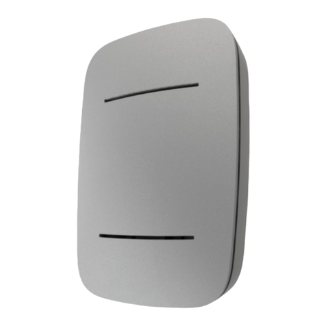
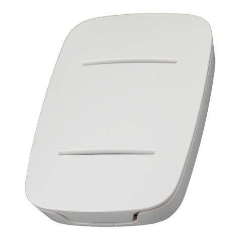
Talkpool OY1410 User manual

OY1410 Pulse meter manual
This manual offers a simple 5-step guide for getting started with the sensor, as well as
configuration with Talkpool’s Sensepool visualization layer and information for advanced
users.
The OY1400 Industrial communication and control unit is designed with focus on ease-of-use
and reliable operation in LoRaWAN networks. The product is dedicated to be used together
with BMeters’ IWM sensor. Normal users will only need to read the 5-step guide at the
beginning of this manual.

Digital activation
Standard devices are configured to use OTAA (Over The Air Activation). It is possible to
order a batch of devices configured for ABP (Activation By Personalization).
Standard devices are configured with the AppEUI (a.k.a. JoinEUI) 70-B3-D5-D7-2F-F8-14-
02. It is possible to order a batch of devices configured with a customer unique AppEUI from
the Talkpool OUI.
Upon receiving your OY1400 Industrial Control and communication unit you should first
provision it to your network server. The product comes with the following:
1.!Dev EUI (also can be found on the outside of the unit)
2.!App Key
These codes are unique for each sensor. The Dev EUI can be seen as a simple identification
code, the App Key is a securely generated authentication code.
The first step you should take is to simply provision the network server, this can be
Talkpool’s solution called Sensepool or any other system that you would like to integrate the
sensor with, with your App EUI.
The second step is to provision the application server with your unique Dev EUI and App
Key.
Digital activation process
After the digital activation the sensor has to be physically activated and installed.
1
Provision network server with App EUI
2
Provision application server with unique Dev EUI and
App Key

Physical installation
When the sensors have been digitally configured it is time to physically activate and install
them. The OY1410 is dedicated to use together with BMeters’ IWM-PL3 or IWM-PL4 units.
First install and configure the IWM-PL3 or IWM-PL4 unit according to BMeters’ instruction.
It is important to configure it according to the table below:
Setting
Value
K index
Set depending on watermeter, see table below
Pulse ratio X
Set to same a K-index
OUT3
Absolute count
Pulse length
80
The K-index and Pulse ratio X defines the number of liters per pulse. It is important that the
Oy1410 is configured with the same setting. The table below shows the settings for different
watermeter models:
Watermeter model
K index
Pulse Ratio X
IWM Pulse Ratio on OY1410
GMDM-I AF
1
1
1
GMDM-I AC
1
1
1
GMB-I
1
1
1
WDE-K50 AF
(up to DN125)
10
10
10
WDE-K50 AF
(DN150 and DN200)
100
100
100
WDE-K50 AC
(up to DN125)
10
10
10
WDE-K50 AC
(DN150 and DN200)
100
100
100

Open the OY1410 using a screwdriver. Replace the right cable gland with the supplied blind
plug. The enclosure has two openings that can be used for wall mounting.
The cable from IWM-PL3 and IWM-PL4 has four wires. Cut the white wire since it will not
be used and might cause short circuits if it is left unconnected inside the OY1410. Feed the
cable though the left cable gland.
Connect the IWM-PL3 or IWM-PL4
according to the table below as illustrated
by the picture to the right.
White cable
Cut
Yellow cable
Ch2 0-10V
Green cable
Ch1 0-10V
Brown cable
GND
Make sure that both jumpers are set to 0-10V as illustrated by the picture below.
After that you install the (replaceable) batteries,
which activates the unit, you close the box and
start measuring your data!

Physical installation process
you require more advanced information on the OY1410 Pulse meter, please check the next
sections.
3
Open the unit, connect the sensor and verify the jumper
settings.
4
Install batteries, activating the OY1410
5
Close unit and install in location, you can now view the first
data coming in on your application server

Function description
The OY1410 counts the pulses output by the IWM-PL3 or IWM-PL4. The corresponding
water volume depends on the set “Pulse ratio X”-value in the IWM-PL3 or IWM-PL4, which
in turn depends on the type of water meter used. To get the OY1410 to report water volume in
liter it is required to set the IWM Pulse Ratio to the same value as Pulse Ratio X in the IWM-
PL3 or IWM-PL4.
The OY1410 also supervises the fraud signal from the IWM-PL3 or IWM-PL4. If a fraud
condition is detect based on the output from the IWM unit the fraud detection indicator in the
LoRa uplink message will be set in coming reports until the fraud detection indicator has been
explicitly cleared using a LoRa downlink request.
The OY1410 also detects if the batteries are replaced, since it will not be able to count the
pulses from the IWM-PL3 or IWM-PL4 while the batteries are not inserted. When the
batteries have been replaced the reset detection indicator in the LoRa uplink message will be
set in the coming reports until the reset detection indicator has been explicitly cleared using a
LoRa downlink request. Note: The reset signal is also set during the first startup.
It is possible to set the counter value in the OY1410 to a preset value using a LoRa downlink
request.

Protocol
!
This!describes!the!payload!data!that!is!sent!to!and!from!the!application!server.
!
Uplink command device => network
Field
Bytes
Value
Description
Note
Type
1
xx
0x01: Data
0x02: Command NACK
Index
1
xx
Command Index
Data
As defined for Command Index (only for Type: Data)
!
Downlink command network => device
Field
Bytes
Value
Description
Note
Type
1
xx
0x01: Set
0x02: Query
0x03: Action
Index
1
xx
Command Index
Data
As defined for Command Index

Commands!
Index
Description
Datatype
Encoding
Valid range
Access
Unsolicited
Description
Note
0x03
FW build hash
6 x Uint8
Query
No
Unique number that identifies the
firmware version
0x05
Device reset
Action
No
Reset of device
0x06
CPU voltage
Uint8
25mV/
LSB
0-3.6V
Query
No
Read CPU voltage. Max/min ranges
depend on battery chemistry.
0x0A
CPU temperature
Uint16
Big endian
0.01C / LSB
-50- +125 C
Query
No
Temperature from CPU sensor with 50
°C offset. Approximately 5 °C accuracy.
0x25
Application type
-
0-1
Query
No
0 = Standard application
1 = LoV application
0x26
Reporting interval
Uint16
Big endian
Minutes
1-10080
Query
Set
No
Measurement interval in minutes
Setting measurement
interval resets the
measurement timer.
0x2B
IWM data
Counter
Status
Uint32
followed by
Uint8
Big endian
Count
followed by
Bitfield
0- 4294967295
followed by
0-3
Query
Yes
Current count and status
Status bitfield:
Bit 0: Reset detected
Bit 1: Fraud detected
Bit 2: Reserved
Bit 3: Reserved
Bit 4: Reserved
Bit 5: Reserved
Bit 6: Reserved
Bit 7: Reserved
0x2C
IWM set counter
Uint32
Big endian
Count
0- 4294967295
Set
No
Set counter to a predefined value
0x2D
IWM reset status
Uint8
Bitfield
-
Set
No
Resets the selected alarm status bits.
When a bit in the
request is not set
(=0) the
corresponding bit in
the status is cleared.
0x2E
IWM pulse ratio
Uint16
Liters/pulse
1-10000
Query
Set
No
Liters of water per pulse
!
!

Command examples!
Uplink: 012B0000123401
Current counter value is 1234HEX = 4660. Status bit 0 is set indicating a reset has been detected.
•!Setting the reporting interval to 1440 minutes = 24 hours.
Downlink command: 012605A0
•!Reset the Status bits.
Downlink command: 012D00
•!Set counter value to 100000
Downlink command: 012C000186A0
!
Table of contents
Other Talkpool Measuring Instrument manuals