Talon AT3339AS User manual

1
GENERAL SAFETY RULES GB
WARNING! When using petrol tools, basic safety precautions, including the following, should always be followed to
reduce the risk of serious personal injury and/or damage to the unit.
Read all these instructions before operating this product and save these instructions.
WARNING • PLEASE READ
For your own safety please read this manual before attempting to operate your new unit. Failure to follow instructions
can result in serious personal injury. Spend a few moments to familiarize yourself with your trimmer before each use.
MODEL NO. AT3339AS
SAFETY
OPERATION
MAINTENANCE
Petrol String Trimmer
USER MANUAL
READ YOUR USER MANUAL AND ALL SUPPLE-
MENTS (IF ANY ENCLOSED) THOROUGHLY BEFORE
OPERATING YOUR UNIT.
1. Wear close fitting, tough work clothing that will
provide protection, such as long slacks or trousers,
safety work shoes, heavy duty work gloves, hard hat,
a safety face shield, or safety glasses for eye protec-
tion and a good grade of ear plugs or other sound
barriers for hearing protection.
2. Store in a safe place.
Open fuel cap slowly to release
any pressure which may have formed in fuel tank. To
prevent a fire hazard, move at least 10 feet (3 meters)
from fueling area before starting.
3. Turn unit off before setting it down.
4. Always hold unit firmly with both hands, the
thumb and fingers encircling the handles.
5. Keep all screws and fasteners tight. Never operate
your equipment when it is improperly adjusted or not
completely and securely assembled.
6. Keep handles dry, clean and free of fuel mixture.
7. Keep linehead as close to ground as practical.
Avoid hitting small objects with linehead. When cut-
ting on a slope, stand below linehead. NEVER cut or
trim on a hill or slope, etc. if there is the slightest
chance of slipping, sliding or losing firm footing.
8. Check area you will be trimming for debris that
may be struck or thrown during operation.
9. Keep all parts of your body and clothing away
from linehead when starting or running engine.
Before starting engine, make sure linehead will not
come in contact with any obstacle.
10. Stop engine before examining trimming line.
11. Store equipment away from possible flammable
materials, such as gas-powered water heaters, clothes
dryers, or oil-fired furnaces, portable heaters, etc.
12. Always keep the debris shield, linehead, and engine
free of debris build-up.
13. Operation of equipment should always be restricted
to mature and properly instructed individuals.
1. DO NOT USE ANY OTHER FUEL than that recom-
mended in your manual. Always follow instructions in
the Fuel and Lubrication section of this manual.
Never use gasoline unless it is properly mixed with 2-
cycle engine lubricant. Permanent damage to engine
will result, voiding manufacturer’s warranty.
2. DO NOT SMOKE while refueling or operating
equipment.
3. DO NOT OPERATE UNIT WITHOUT A MUFFLER
and properly installed muffler shield.
4. DO NOT TOUCH or let your hands or body come in
contact with the muffler. Hold unit with thumbs and
fingers encircling the handles.
5. DO NOT OPERATE UNIT IN AWKWARD POSI-
TIONS, off balance, outstretched arms, or one-hand-
ed. Always use two hands when operating unit with
thumbs and fingers encircling the handles.
6. DO NOT RAISE LINEHEAD above ground level
while unit is operating. Injury to operator could result.
7. DO NOT USE UNIT FOR ANY PURPOSES OTHER
than trimming lawn or garden areas.
8. DO NOT OPERATE UNIT FOR PROLONGED PERI-
ODS. Rest periodically.
9. DO NOT OPERATE UNIT WHILE UNDER THE
INFLUENCE OF ALCOHOL OR DRUGS.
10. DO NOT OPERATE UNIT UNLESS DEBRIS SHIELD
AND/OR GUARD IS INSTALLED AND IN GOOD
CONDITION.
11. DO NOT ADD, REMOVE OR ALTER ANY COMPO-
NENTS OF THIS PRODUCT. Doing so could cause
personal injury and/or damage the unit voiding the
manufacturer’s warranty.
12. DO NOT operate your unit near or around flammable
liquids or gases whether in or out of doors. An explo-
sion and/or fire may result.
WARNING: Keep children, bystanders, and
animals 50 feet (15 meters) away. If
approached stop unit immediately.
WHAT NOT TO DO
Meaning of symbols marked on the product
Read the user manual before using the machine
Whenever the machine is in use, safety goggles
must be worn to safeguard against flying object, as
must ear protectors, such as a soundproof helmet,
in order to protect the operator’s hearing. If the
operator is working in an area where there is a risk
of falling objects, a safety helmet must also be
worn.
Wear safety boots to protect against electric shock
Danger : Objects thrown up by machine
Keep people or animals at least 15m away from the
machine during operation
Wear gloves to protect your hands
Warning! Hot surface
Maximum revolution frequency of the drive shaft
9096-333901

3
GB
2
GB
GENERAL IDENTIFICATION
3
45
6
8
9
12
13
10
7
2
11
14
15
16
SAFETY FEATURES
13 MUFFLER SHIELD helps prevent hands, body and/or combustible materials from making contact with a hot muffler.
1. LINEHEAD
2. DEBRIS SHIELD
3. DRIVE SHAFT ASSEMBLY
4. HANDLE
5. THROTTLE TRIGGER
6. IGNITION SWITCH
7. SAFETY TRIGGER LOCK
8. CHOKE LEVER
9. STARTER ROPE HOUSING
10. FUEL TANK
11. AIR FILTER COVER
12. STARTER HANDLE
13. MUFFLER SHIELD
14. PRIMER BULB
15. HARNESS
16. TOOL-LINK COUPLING
1
Engine Type . . . . . . . . . . . . . . . . . . . . . . . . . . . . . . . . . . . . . . . . . . . . .Air-cooled, 2-Cycle, Chrome Cylinder
Displacement . . . . . . . . . . . . . . . . . . . . . . . . . . . . . . . . . . . . . . . . . . . .25cc
Weight . . . . . . . . . . . . . . . . . . . . . . . . . . . . . . . . . . . . . . . . . . . . . . . . . .7.8Kg
Fuel Capacity . . . . . . . . . . . . . . . . . . . . . . . . . . . . . . . . . . . . . . . . . . . . .450 ml
Drive Shaft Length . . . . . . . . . . . . . . . . . . . . . . . . . . . . . . . . . . . . . . . . .142cm
Bump Head . . . . . . . . . . . . . . . . . . . . . . . . . . . . . . . . . . . . . . . . . . . . . .Twin Line
Cutting Width . . . . . . . . . . . . . . . . . . . . . . . . . . . . . . . . . . . . . . . . . . . . .43cm
Cutting Line . . . . . . . . . . . . . . . . . . . . . . . . . . . . . . . . . . . . . . . . . . . . . .2.5mm
Handle . . . . . . . . . . . . . . . . . . . . . . . . . . . . . . . . . . . . . . . . . . . . . . . . . .“J” Handle
Ignition . . . . . . . . . . . . . . . . . . . . . . . . . . . . . . . . . . . . . . . . . . . . . . . . . .Electronic
Drive . . . . . . . . . . . . . . . . . . . . . . . . . . . . . . . . . . . . . . . . . . . . . . . . . . .Centrifugal Clutch
Shaft Type . . . . . . . . . . . . . . . . . . . . . . . . . . . . . . . . . . . . . . . . . . . . . . .Straight - Tool-Link
SPECIFICATIONS
• “J” HANDLE ASSEMBLY
1. To install handle onto unit, you will need the following
components from your user kit: “J” handle (A), fixing
holder (B), clamps (C) and screws (D). (Fig. 1)
2. Install the fixing holder (B) on the shaft around 4” (10-
12cm) away from the end of the grip, put the clamp
(C)over shaft and tighten the 2 screws (D).
3. Install the J handle (A) on the fixing holder, put the
other clamp (C) over J-handle and tighten the other 2
screws (D).
•DRIVE SHAFT
Installing the lower shaft
1. Remove the cover from the lower shaft (A). Press the
release lever (B) while pushing the lower shaft into the
tool-link couping. (Fig. 2A)
2. Locate and lock the release lever into the primary hole
(C) in the shaft. (Fig. 2A)
3. Tighten the knob (D) securely clockwise before using
the unit. (Fig. 2B)
• DEBRIS SHIELD & DEBRIS SHIELD SKIRT
1. Install debris shield and blade guard with 3 screws (A)
provided (Fig. 3A).
2. Turn the unit over and install the debris shield skirt (B).
Fig. 3B
• LINEHEAD INSTALLATION
1. Install gear collar (C) ensuring that collar spacer (D) is
in place (Fig. 3C).
2. Insert holding pin (E) and thread linehead onto shaft.
Tighten linehead by hand only (Fig. 3D and 3E).
ASSEMBLY INSTRUCTIONS
Fig. 1
A
B
CD
D
C
CAUTION: Make sure the release lever is
locked in the primary hole and knob is
securely tightened before operating this unit.
CAUTION: All attachments are designed to
be used in the primary hole unless otherwise
indicated in the specific attachment’s opera-
tor’s manual. If the incorrect hole is used, it
could result in injury, or damage to the unit.
B
AFig. 2A Fig. 2B
C
D
Fig. 3A Fig. 3B
A
B

5
GBGB
4
•FUEL
Use regular grade unleaded gasoline mixed with 2-cycle
engine oil in 25:1 ratio for best results. Use mixing ratios
in Section FUEL MIXING TABLE.
•MIXING FUEL
Mix fuel with Talon brand 2 cycle oil in an approved con-
tainer. Use mixing table for correct ratio of fuel to oil.
Shake container to ensure thorough mix.
•FUEL MIXING TABLE
•RECOMMENDED FUELS
Some conventional gasolines are being blended with oxy-
genates such as alcohol or an ether compound to meet
clean air standards. Your Talon engine is designed to
operate satisfactorily on any gasoline intended for auto-
motive use including oxygenated gasolines.
•FUEL AND LUBRICATION
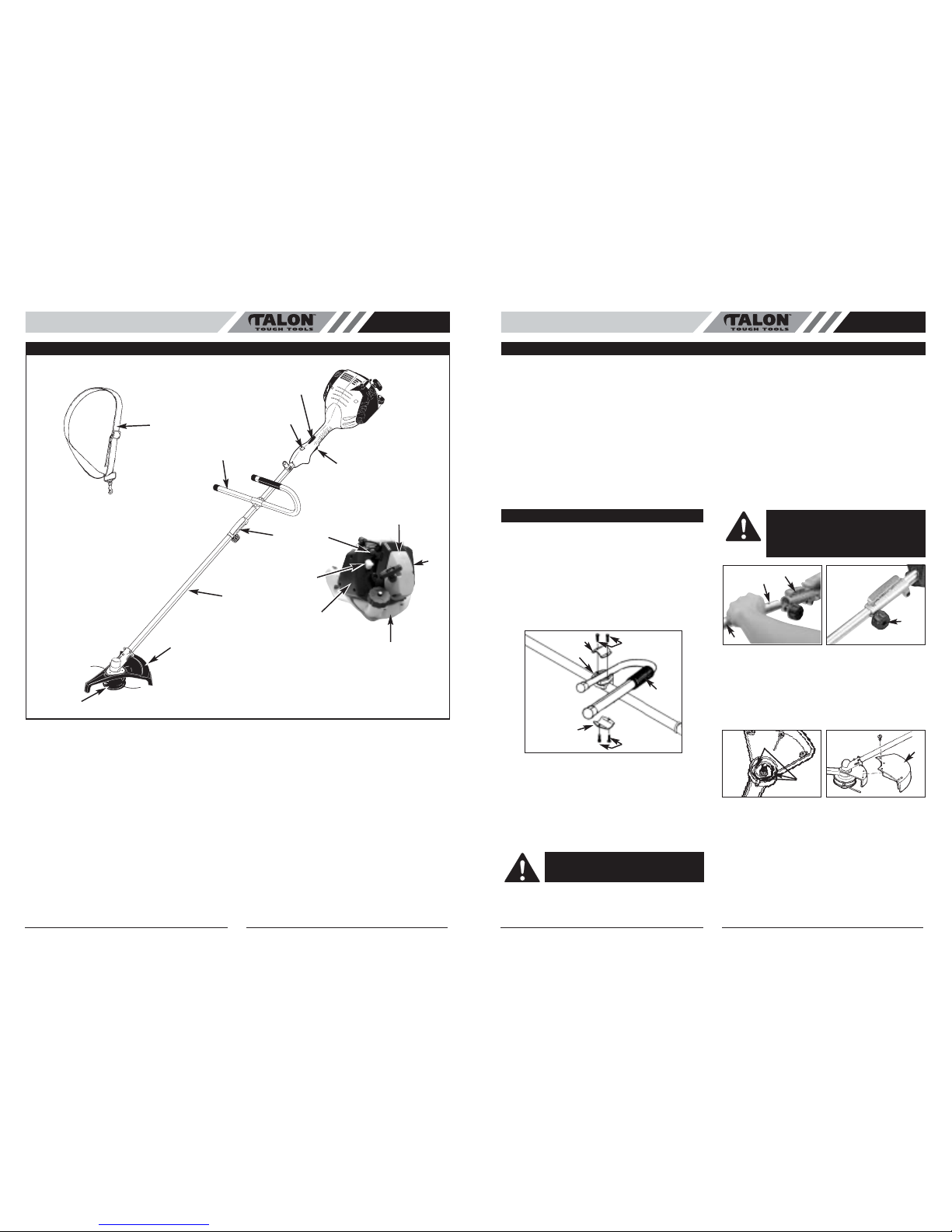
• SHOULDER HARNESS
1. Put the harness on so the shoulder strap is over your
LEFT shoulder.
2. Attach the harness clip (A) to the clip (B) fitted onto
the shaft (Fig. 4A and 4B).
3. Adjust length of shoulder strap so linehead is parallel
to the ground as it hangs from the strap. A few prac-
tice swings without starting engine should be made to
determine correct balance.
NOTE: Detach the shoulder harness from the unit before
starting engine.
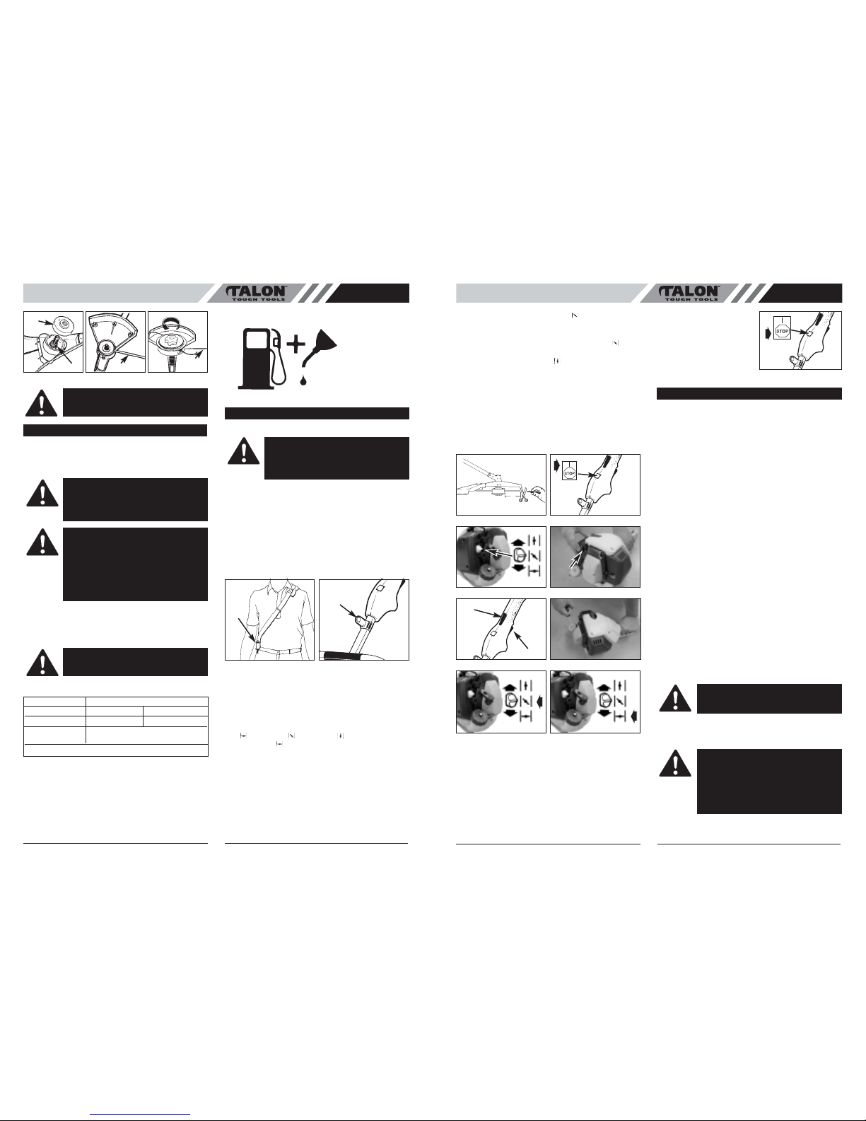
•STARTING A COLD ENGINE
NOTE: To minimize load on engine during starting and
warm-up, trim excess trimming line to 5" (13cm) (Fig. 5A).
1. Move ignition switch to the “RUN (I)” position (Fig.
5B).
2. Your unit is designed with a 3 position choke: CHOKE
“”, PARTIAL “ ”, and RUN “ ”. Move choke lever
to CHOKE “ ” position (Fig. 5C).
3. Prime the carburetor. Pump the primer bulb (A) 10
times (Fig. 5D).
4. Grip handle firmly – depress safety trigger lock (B) &
throttle trigger (C) to the FULL THROTTLE position
(Fig. 5E).
5. Asmooth rapid pull is required for a strong spark. Pull
starter rope briskly 4 times. (Fig. 5F)
Fig. 3D
EFig. 3EFig. 3C
E
D
C
CAUTION: Skirt must be installed to proper-
ly dispense cutter line and protect operator
FUEL AND LUBRICATION
WARNING: Never use straight gasoline in
your unit. This will cause permanent engine
damage and void the manufacturer’s warran-
ty for that product. Never use a fuel mixture
that has been stored for over 90 days.
WARNING: If 2-cycle lubricant other than
Talon Custom Lubricant is to be used, it must
be a premium grade oil for 2-cycle air cooled
engines mixed at a 25:1 ratio. Do not use any
2-cycle oil product with a recommended
mixing ratio of 100:1. If insufficient lubrication
is the cause of engine damage, it voids the
manufacturer’s engine warranty for that
occurrence.
WARNING:
Lack of lubrication voids engine
warranty. Gasoline and oil must be mixed at
25:1.
GASOLINE 25:1 Ratio Lubricant
5 Liters 6.7 oz. 200ml (cc)
1 lmp. Gal. 6.1 oz. 180ml (cc)
Mixing 25 Parts Gasoline
Procedure to 1 part Lubricant
1ml = 1cc
Gasoline and Oil
Mix 25:1
OPERATING INSTRUCTIONS
Fig. 4A
A
B
Fig. 4B
WARNING: ALWAYS WEAR SHOULDER
HARNESS when operating unit with a blade.
Attach harness to trimmer after starting unit
and engine is running at IDLE. Turn ENGINE
OFF before disconnecting shoulder harness.
6. Move choke lever to PARTIAL “ ” position (Fig. 5G).
7. Pull starter rope again 4 times while trigger is in the
full throttle position (Fig. 5F)
8. Once engine starts, leave in the PARTIAL “ ” posi-
tion for 10 seconds.
9. Move the choke to RUN “ ” position (Fig. 5H).
10. If engine fails to start, repeat steps 1 through 7.
NOTE: If engine fails to start after repeated attempts,
refer to Troubleshooting section.
NOTE: Always pull starter rope straight out. Pulling starter
at an angle will cause rope to rub against the eyelet. This
friction will cause the rope to fray and wear more quickly.
Always hold starter handle when rope retracts. Never
allow rope to snap back from extended position. This
could cause rope to snag or fray and also damage the
starter assembly.
•WARM ENGINE START
1. Place trimmer on firm flat surface.
2. Move ignition switch to the “RUN (I)” position (Fig. 5B).
3. Grip handle firmly, squeeze throttle trigger to FULL
THROTTLE position.
4. Pull starter rope briskly until engine starts, but no more
than 6 times.
5. If engine does not start, please operate “STARTING A
COLD ENGINE” again.
•TO STOP ENGINE
Release throttle trigger. Let
engine return to idle. Push and
hold ignition stop switch (A)
until engine stops (Fig. 6).
•ADDITIONAL SAFETY PRECAUTIONS
Before operating your unit, review ALL SAFETY PRE-
CAUTIONS in this manual.
WARNING / CAUTION
•IF UNFAMILIAR WITH TRIMMING techniques,
practice the procedures with ENGINE in “OFF”
position.
•ALWAYS CLEAR WORK area of debris such as cans,
bottles, rocks, etc. Striking objects can cause serious
injury to operator or bystanders and also damage
equipment. If an object is accidentally hit, immediately
TURN ENGINE OFF and examine equipment. Never
operate unit with damaged or defective equipment.
•ALWAYS TRIM OR CUT AT HIGH ENGINE SPEEDS.
Do not run engine slowly at start or during trimming
operations.
•DO NOT use equipment for purposes other than
trimming or mowing weeds.
•NEVER raise linehead above knee height during
operation.
•DO NOT operate unit with other people or animals in
the immediate vicinity. Allow a minimum of 30 feet (10
meters) between operator and other people and
animals when trimming or mowing. Allow a distance of
100 feet (30 meters) between operator and other
people and animals when SCALPING with linehead
cutter.
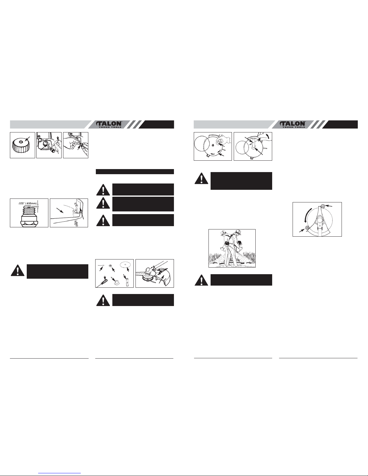
•IF OPERATING UNIT ON A SLOPE, stand below the
cutting attachment. DO NOT OPERATE on a slope or
hilly incline if there is the slightest chance of slipping or
losing your footing.
•LINEHEAD LINE RELEASE
To release fresh line, run engine at full throttle and “bump”
linehead against lawn. Line will automatically release. The
knife in debris shield will trim excess line (Fig. 7A).
Fig. 5A Fig. 5B
5”
(13cm)
Fig. 5C Fig. 5D
A
Fig. 5E Fig. 5F
B
C
Fig. 5G Fig. 5H
Fig. 6
TRIMMING INSTRUCTIONS
WARNING:
DO NOT use steel wire or plastic-
coated steel wire of any kind with your line-
head. Serious operator injury can result.
CAUTION: Periodically remove weed wrap to
prevent overheating the drive shaft. Weed
wrap occurs when strands of weed become
entangled around the shaft beneath the
debris shield (Fig. 7B). This condition pre-
vents the shaft from being properly cooled.
Remove weed wrap with screwdriver or sim-
ilar device.

7
GB
6
GB
•TRIMMING PROCEDURES
When properly equipped with a debris shield and line-
head, your unit will trim unsightly weeds and tall grass in
those hard-to-reach areas - along fences, walls, founda-
tions and around trees. It can also be used for scalping to
remove vegetation down to the ground for easier prepara-
tion of a garden or to clean out a particular area.
NOTE: Even with care, trimming around foundations,
brick or stone walls, curves, etc., will result in above nor-
mal string wear.
TRIMMING / MOWING
Swing trimmer with a sickle-like motion from side to side.
Do not tilt the linehead during the procedure. Test area to
be trimmed for proper cutting height. Keep linehead at
same level for even depth of cut (Fig. 8A).
CLOSER TRIMMING
Position trimmer straight ahead with a slight tilt so bottom
of linehead is above ground level and line contact occurs
at proper cutting point.Always cut away from operator. Do
not pull trimmer in toward operator.
FENCE / FOUNDATION TRIMMING
Approach trimming around chain link fences, picket
fences, rock walls and foundations slowly to cut close
without whipping line against the barrier. If the line comes
in contact with rock, brick walls, or foundations, it will
break or fray. If string snags fencing, it will snap off.
TRIMMING AROUND TREES
Trim around tree trunks with a slow approach so line does
not contact bark. Walk around the tree trimming from left
to right. Approach grass or weeds with the tip of the string
and tilt linehead slightly forward.
SCALPING
Scalping refers to removal of all vegetation down to the
ground. To do this, tilt the linehead to about a 30 degree
angle to the right. By adjusting the handle you will have
better control during this operation. Do not attempt this
procedure if there is any chance flying debris could injure
operator, other people or cause damage to property (Fig.
8B)
EDGING FUNCTION:
1. Loosen knob (B) by turning counter clockwise (Fig.
8C).
2. Push down release lever (A) and twist shaft to desired
position (Fig. 8C). Edging holes positioned at 90
degrees left, 90 degress right and 180 degrees.
3. Lock lower shaft in desired edging hole with release
lever.
4. Tighten knob (B)securely before use by turning clock-
wise.
TOOL-LINK ATTACHMENTS:
1. Loosen knob (B) by turning counter clockwise (Fig.
8D).
2. Push down release lever (A) and remove lower shaft
(Fig. 8D).
3. Insert tool-link attachment shaft and lock in primary
hole (C) with release lever.
4. Tighten knob (B) securely before use by turning clock-
wise.
Fig. 7BFig. 7A
BUMP
Fig. 8A
WARNING: Use extreme caution when
SCALPING. Keep a distance of 100 feet (30
meters) between operator, other people and
animals during these operations.
Fig. 8B
Fig. 8C Fig. 8D
A
C
B
A
B
WARNING:
DO NOT SWEEP WITH TRIMMER
Sweeping refers to tilting linehead to sweep
away debris from walkways, etc. Your trim-
mer is a powerful tool and small stones or
other such debris may be hurled 50 feet (15
meters) or more, causing injury or damage to
nearby property such as automobiles, homes
and windows.
•REPLACING TRIMMING LINE
1. Turn the knob (A) CLOCKWISE and remove it (Fig.
9A).
2. Remove the spool (C), and spring (D) from spindle
(E)
3. Remove any remaining trimming line.
4. Double a 32' (9.8m) length of .095 (2.5mm) cutter
line. Place the looped center in one of the slots (G) of
the spool divider (Fig. 9B).
5. Wind as shown in illustration (Fig. 9C), keeping ten-
sion, with each half separated by the spool divider.
Wind to within 6" (15cm) of the ends.
6. Lock each end of line into a slot (H) on opposite sides
of the spool (Fig. 9D).
7. Install the spring (D) over the spindle (E). Insert each
end of the line through an eyelet (H) in the housing
(F) (Fig. 9E).
8. Lower the spool into the housing (F) while feeding the
line through the eyelets (H). Ensure the spring seats
itself into the spool (Fig. 9E).
9. Once the spool is in place, apply pressure on the
spool compressing the spring. Pull each end of the
line (K) sharply to unlock the line from the slots (Fig.
9F).
10. Continue to apply pressure to the spool until the knob
can be threaded COUNTER CLOCKWISE onto the
spindle. Tighten the knob securely by hand only (Fig.
9G).
11.Trim the excess line to approximately 5" (13cm). This
will minimize load on engine during starting and
warm-up (Fig. 9H).
•AIR FILTER
To Clean Air Filter:
1. Remove 3 screws (A) holding air filter cover in place.
Tilt cover (B) to allow access to filter element and lift
filter (C) from air box. (Fig. 10)
2. Wash filter in soap and water. DO NOT USE GASO-
LINE!
3. Air dry filter.
4. Reinstall filter.
NOTE: Replace filter if frayed, torn, damaged or unable to
be cleaned.
• FUEL CAP / FUEL FILTER
NOTE: Keep vent (A) on fuel cap clean of debris (Fig.
11A).
Fuel Filter:
1. Lift fuel line (B) out of tank. A steel wire (C) with a
hook or a paper clip works well (Fig. 11B).
2. Pull off with a twisting motion (Fig. 11C).
3. Replace fuel filter (D) (Fig. 11C).
NOTE: Never operate the trimmer without the fuel filter.
Internal engine damage could result!
A. KNOB
B. TRIMMING LINE
C. SPOOL
D. SPRING
E. SPINDLE
F. HOUSING
G. SLOTS
H. EYELETS
A
Fig.9A B
C
D
E
H
GF
Fig. 9B Fig. 9C
Fig. 9E
Fig. 9H
5”
(13mm)
H
D
F
E
H
Fig. 9D
Fig. 9F Fig. 9G
G
G
K
K
MAINTENANCE INSTRUCTIONS
CAUTION:
NEVER operate trimmer without
the air filter. The air filter must be kept clean.
If it becomes damaged, install a new filter.
Fig. 10
B
A
C
CAUTION: Remove fuel from unit and store in
approved container before starting this proce-
dure. Open fuel cap slowly to release any
pressure which may have formed in fuel tank.

9
GB
•CUTTING WITH BLADES
Always wear eye protection and protective clothing when
cutting with a blade.
Always use the harness for blade operations.
•USING WEED BLADES
SCYTHING WEEDS
Scything refers to cutting by moving the blade from side to
side in a level arc. It is most effective with grassy weeds
and light undergrowth. It should not be used to cut large,
tough weeds or woody growth (Fig. 15).
•USING A BRUSH BLADE
SCYTHING
Scything may be used with a brush blade for light brush
and undergrowth. It is not recommended for tough growth.
SAWING
Larger brush and saplings should be sawed. Do not
attempt to saw growths larger than 3 inches (7.5 cm) in
diameter.
Sawing is using the brush blade optional much like a cir-
cular saw. Make gradual cuts backing out every 1/2 inch
(1.3 cm) or so to prevent binding.
BINDING
Top heavy growth such as saplings and heavy brush can
bind and stop the blade. Avoid binding by anticipating
which way the growth will lean, and cut from the opposite
side.
If the blade binds in a cut stop the engine immediately.
Hold the unit up to prevent the blade from cracking or
breaking while pushing the sapling away from the cut to
free the blade.
AVOID KICKOUT
Kickout is the reaction of a moving blade if it contacts a
strong tree, brush or a solid object. The force that occurs
violently pushes the blade away in an arc. Kickout could
cause loss of control resulting in injury to the operator or
bystanders.
DO NOT USE A BLADE NEAR A CHAIN LINK FENCE,
METAL STAKES, LANDSCAPE BORDERS OR BUILD-
ING FOUNDATIONS.
The Talon blade guard is designed to reduce the risk of
kickout by providing stops to brace the unit against the
object being cut.
Place the sapling against the stop (A) so the rotation of
the blade continually draws it into the stop (A) (Fig. 16).
This provides greater control for the operator.
8
GB
•CARBURETOR ADJUSTMENT
The carburetor was pre-set at the factory for optimum per-
formance. If further adjustments are necessary, please
take your unit to the nearest Authorized Service Center.
•SPARK PLUG
1. Spark plug gap = .025" (.635mm) (Fig. 12).
2. Torque to 105 to 130 inch pounds (12 to 15 N•m).
Connect spark plug boot.
•DEBRIS SHIELD KNIFE SHARPENING
1. Remove cutter knife (E) from debris shield (F) (Fig.
13).
2. Place knife in a bench vise. Sharpen knife using a flat
file, being careful to maintain the angle of cutting
edge. File in one direction only.
•STORING A UNIT
1. Perform all the general maintenance recommended
in the Maintenance Section of your User Manual.
2. Clean exterior of engine, drive shaft assembly, debris
shield and linehead.
3. Drain fuel from the fuel tank.
4. After fuel is drained, start engine.
5. Run engine at idle until unit stops. This will purge the
carburetor of fuel.
6. Allow engine to cool (approx. 5 minutes).
7. Using a spark plug wrench, remove the spark plug.
8. Pour 1 teaspoon of clean 2-cycle oil into the
combustion chamber. Pull starter rope slowly several
times to coat internal components. Replace spark
plug.
9. Store unit in a cool, dry place away from any source
of ignition such as an oil burner, water heater, etc.
•REMOVING A UNIT FROM STORAGE
1. Remove spark plug.
2. Pull starter rope briskly to clear excess oil from com-
bustion chamber.
3. Clean and gap spark plug or install a new spark plug
with proper gap.
4. Prepare unit for operation.
5. Fill fuel tank with proper fuel / oil mixture. See Fuel
and Lubrication Section.
•BLADE INSTALLATION
1. To install the blade you will need the items illustrated
below (screwdriver not provided): holding pin (A),
retaining nut (B), blade (C), screwdriver (D), flange
(E), socket wrench (F) (Fig. 14A)
2. Remove three screws (E). Remove the skirt (A). Use
the holding pin to prevent the collar from turning while
removing the linehead (turn CLOCKWISE). (Fig.
14B)
3. Leave the holding pin in place.
4. Install blade (C) with teeth pointing CLOCKWISE as
shown in the illustration (Fig. 14C).
5. Install flange (E) with FLAT SURFACE facing blade
(Fig. 14C).
NOTE: Make sure blade is centered on collar arbor.
6. Tighten nut (B) securely by turning it COUNTER-
CLOCKWISE with socket wrench (F). Remove hold-
ing pin (Fig. 14D).
A
Fig. 11A Fig. 11B
D
Fig. 11C
C
B
Fig. 12 Fig. 13
F
E
WARNING: Failure to follow these steps may
cause varnish to form in the carburetor and
difficult starting or permanent damage follow-
ing storage.
OPTIONAL BLADE ATTACHMENT
CAUTION: NEVER use unit if blade is
warped or has teeth that are chipped or miss-
ing. Replace a damaged blade immediately.
CAUTION: Always wear heavy-duty work
gloves when handling and installing a blade.
CAUTION: NEVER operate unit with a blade
unless metal blade guard is properly
installed. NEVER operate a unit with a dam-
aged guard.
Fig. 14A
D
AB
EC
F
Fig. 14B
E
A
WARNING: Be sure the blade center hole is
properly sized to the collar arbor.
Fig. 14C
F
Fig. 14D
E
C
E
CAUTION : Before operating this machine
with a blade check to ensure it is properly
installed. Follow all warnings listed in the
blade safety precautions section in this man-
ual.
Fig. 15
CAUTION: Do not use weed blades to cut
brush or tree saplings.
Fig. 16
A
A

TROUBLE SHOOTING THE ENGINE
PROBLEM
Unit won’t start or starts but will not run.
Unit starts, but engine has low power.
Engine hesitates.
No power under load.
Runs erratically.
Smokes excessively.
PROBABLE CAUSE
Incorrect starting procedures.
Incorrect carburetor mixture adjustment
setting.
Fouled spark plug
Fuel filter plugged.
Incorrect lever position on choke.
Dirty spark arrester screen.
Dirty air filter.
Incorrect carburetor mixture adjustment
setting.
Incorrect carburetor mixture adjustment
setting.
Incorrectly gapped spark plug.
Incorrect carburetor mixture adjustment
setting.
Incorrect fuel mixture.
CORRECTIVE ACTION
Follow instructions in the User Manual.
Have carburetor adjusted by an Authorized
Service Center.
Clean / gap or replace plug.
Replace fuel filter.
Move to RUN position.
Replace spark arrester screen.
Remove, clean and reinstall filter.
Have carburetor adjusted by an Authorized
Service Center.
Have carburetor adjusted by an Authorized
Service Center.
Clean / gap or replace plug.
Have carburetor adjusted by an Authorized
Service Center.
Use properly mixed fuel (25:1 mixture).
GB
10
Table of contents
Other Talon Trimmer manuals
Popular Trimmer manuals by other brands

Zenoah
Zenoah SRTZ2500 Owner's/operator's manual

Husqvarna
Husqvarna 122c SERIES Operator's manual

Troy-Bilt
Troy-Bilt Super branco TB415CS Operator's manual

Little Wonder
Little Wonder SINGLE EDGED 1910 owner's manual

Wolf Garten
Wolf Garten Blue Power GT 830 instruction manual

Qualcast
Qualcast Qhte600 instruction manual