manuals.online logo
Brands
  1. Home
  2. •
  3. Brands
  4. •
  5. Tamco
  6. •
  7. Fire And Smoke Damper
  8. •
  9. Tamco 1000 SM Series Instruction sheet

Tamco 1000 SM Series Instruction sheet

www.tamcodampers.com
© T.A. Morrison & Co. Inc., 2017
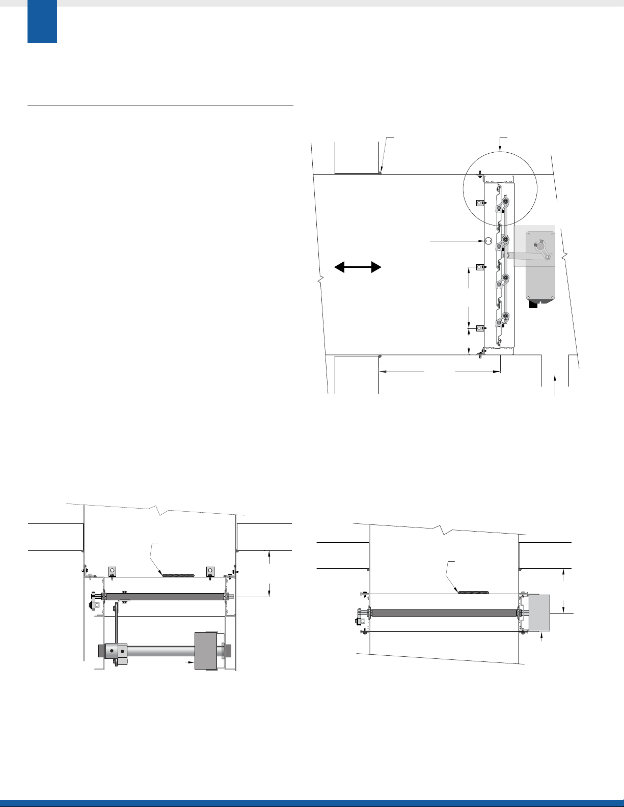
FRONT / TOP END UP / RIGHT HAND
CALL TAMCO CUSTOMER SERVICE WITH ANY
QUESTIONS CONCERNING TAMCO SMOKE DAMPERS.
DO NOT ADJUST LINKAGE MECHANISM.
IF PROBLEM STILL EXISTS AFTER VERIFICATION AND
CORRECT ACTION, CALL TAMCO CUSTOMER SERVICE.
Note that all technical information available on TAMCO’s website at
www.tamcodampers.com supersedes and takes precedence over all
information contained within the printed catalog.
READ ENTIRE INSTALLATION GUIDELINES MANUAL
BEFORE INSTALLING DAMPERS.
CHECK ALL DAMPER SIZES AND TAGS TO ENSURE
THAT SMOKE DAMPERS ARE INSTALLED IN THEIR
CORRESPONDING OPENINGS.
TAMCO UL/ULC APPROVED SMOKE DAMPER |
Installation Guidelines
For Series 1000 SM & 1000 SM-M
Applies to all Options and Install Types
1
>Any alteration to or deviation from TAMCO's UL Classified, Smoke
Damper Installation Guidelines must be approved by the local AHJ
(Authority Having Jurisdiction).
>Angle clips described in these installation guidelines are minimum
16 ga (1.5 mm) zinc-plated or stainless steel or .125” (3 mm) extruded
aluminum. Angle legs are to be a minimum 1” x 1” (25.4 mm x
25.4 mm) and are to be a minimum ½” (12.7 mm) wide with 0.15"
(4 mm) diameter screw holes. Continuous or full-length zinc-plated,
extruded aluminum, or stainless steel angles are also acceptable.
>Smoke dampers must be installed at, or adjacent to, but no more
than 24" (609 mm) from the point where the duct or opening passes
through the smoke barrier. This must be done in accordance with
NFPA 90A.
>Duct air inlets, outlets or branches shall not be located between the
smoke damper and the smoke barrier.
>Smoke dampers must not be installed in fiberglass-lined ducts in a
manner that will damage the lining material, or interfere with damper
blade operation.
>Provide a duct hanger at a smoke damper location, when the duct
strength is inadequate for the damper and its operator.
>An access door must be provided, if the damper actuator is mounted
inside the duct.
GENERAL INSTALLATION NOTES:
&
>Smoke dampers must be installed square and free from racking, to
ensure proper operation and performance.
>Dampers must be installed without stretching or compression, to
allow them to maintain their original factory adjustment, thereby
retaining their low leakage rating.
>TAMCO Smoke Dampers are approved to be installed either standing
in the vertical plane, or lying in the horizontal plane. If smoke
dampers are installed standing in the vertical plane, damper blades
must be horizontal.
>Only lift dampers via sleeve or damper frame. Never lift damper by
holding on to the damper blades or actuator.
>All connections on the back or rear side of the smoke damper frame
(opposite to sticker side), where the damper makes contact with the
duct, sleeve, or substrate must be sealed using a ⅛" (3.2 mm) bead of
silicone sealant. (See "Installation Procedures for Smoke Damper Install
Types" for recommended silicone seal brands.)
>When installing a multiple-section smoke damper assembly, all joints
where damper frames meet must be sealed, using a bead of silicone
sealant.
>TAMCO Smoke Dampers must be kept in an environment that is free
of dirt, dust, wall texture, paint over-spray, and other contaminants,
prior to and after installation, to ensure proper damper operation and
to guard against damage.
MANUFACTURER'S RECOMMENDATIONS:
&
>When smoke dampers arrive at the job site, inspect all material for
obvious and hidden damage. Report any damage or missing parts to
TAMCO Customer Service.
>Store dampers indoors to protect them from environmental
conditions and to avoid damage.
>All moving parts of the damper must be inspected and cycled at
intervals not greater than every twelve (12) months or in accordance
with the latest edition of NFPA 80, 90A, 92A, local codes and the
actuator manufacturer.
>Dry lubricants are recommended.
>Smoke dampers do not typically require maintenance, if the
environment they are installed in is kept dry and clean.
OPTIONS FOR SERIES 1000 SM & 1000 SM-M:
&
>MR  Moisture Resistance Option
>SW  Salt Water Resistance Option
© T.A. Morrison & Co. Inc., 2017
BELIMO
FSNF 120
12" max
(305 mm)
Back or Rear
Side of Damper
Front Side
of Damper
24" max
(610 mm)
AIRFLOW
Smoke
Barrier
Sealant or fire stopping,
as required by local codes
Brace
Provided when section
height exceeds 37.5" (953 mm)
6" max
(152 mm)
See specific mounting
details on next page
Smoke
Barrier
Air Duct Outlet:
Inlet or Branch
Sealant/Caulk
(Around perimeter)
Smoke
Barrier
Smoke
Barrier
24" max
(610 mm)
Back or Rear Side of Damper
Front Side of Damper
Actuator
IN DUCT INSTALL TYPE SHOWN
JACKSHAFT MOUNTED
(side view)
FLANGED TO DUCT INSTALL TYPE SHOWN
DIRECT COUPLED TO DRIVE ROD
(top view)
IN DUCT INSTALL TYPE SHOWN
JACKSHAFT MOUNTED
(top view)
ACTUATOR WIRING MUST BE CONNECTED IN
ACCORDANCE WITH LOCAL CODES, ORDINANCES,
AND NEC/CSA REGULATIONS.
MULTIPLE ACTUATORS MOUNTED ON A SINGLE
UNIT SHALL BE WIRED TO A SINGLE POINT TO
ALLOW SIMULTANEOUS OPERATION.
OPTIONS FOR ACTUATOR MOUNTING
2
ACTUATOR WIRING GUIDE:
&
>Wiring used to connect each actuator shall be, as a minimum,
No. 16 ga. AWM.
>The minimum temperature rating of the wiring is to be 302°F (150°C).
>All wiring must be routed through a metal conduit or EMT, with
fittings (all UL Listed materials).
>Connections shall occur within the field wiring enclosures integral to
the operators or the UL Listed box.
(See details on next page for other install types.)
Actuator
Smoke
Barrier
Back or Rear Side of Damper
Front Side of Damper
Sealant/Caulk
(Around perimeter)
Smoke
Barrier
24" max
(610 mm)
www.tamcodampers.com
© T.A. Morrison & Co. Inc., 2017
2
646
1
Back or
Rear Side
of Damper
Front, Label,
Jackshaft,
or Actuator
Side of Damper
2
1
4
3
3
4
3
5
Back or
Rear Side
of Damper
Front, Label,
Jackshaft,
or Actuator
Side of Damper
Front, Label,
Jackshaft,
or Actuator
Side of Damper
Back or Rear
or Wall Side
of Damper
2
76
4
1
Opening
8
Smoke
Barrier
INSTALLATION PROCEDURES FOR |
Smoke Damper Install Types
3
*LEGEND:
1. TAMCO Smoke Damper 4. Fastener 7. Extended flange frame
2. Silicone caulk 5. Sleeve /duct 8. Substrate fastener
3. Clip angle 6. Flanged to Duct connection
*SEE
LEGEND
BELOW
²APPROVED SILICONE CAULK:

Dow Corning: RTV Silicone Silastic 732, Xiameter 732, Xiameter SLT 5100

Momentive
Performance Materials: RTV 108
a. Measure and if necessary, adjust the duct or opening to ensure that it
is true and square.
b. Run a bead of silicone caulk² around the inside perimeter of the
flange, where it comes into contact with the damper frame, to
prevent leakage at the connection point between the duct and
damper frame. This step may be performed now or after step "d",
once the smoke damper has been fastened in place.
c. Position the Flanged to Duct mount type smoke damper, so that it is
adjacent to the flanged duct.
d. Secure the flanged connections together using, as a minimum; #8
sms screws, 3
/
16”
(4.8 mm)
rivets, #12 bolts/nuts, flange mount system,
or tack welds, placed at 12”
(305 mm)
oc intervals. Fasteners should
begin at no more than 6”
(152 mm)
from the corners. A minimum of 1
fastener is required per side.
a. Dampers should be ordered from the factory with extended rear
flanges if they are to be wall mounted.
b. Measure both the wall opening and the damper ID, to ensure that the
two dimensions are identical.
c. Run a bead of silicone caulk² around the perimeter of the damper
flange face, where it will come into contact with the substrate upon
installation. This is to prevent leakage between the damper and the
wall. Caulking may be applied at this step, or following step "e", once
the smoke damper has been fastened in place.
d. Place the damper in the desired location on the wall, so that the
inside of the damper's frame aligns with the edges of the wall
opening.
e. Secure the damper to the wall using, as a minimum; #8 sms screws,
3
/
16”
(4.8 mm)
rivets, #12 bolts/nuts, ¼"
(6.4 mm)
Tapcons, or tack
welds, placed at 12”
(305 mm)
oc intervals. Fasteners should begin at
no more than 6”
(152 mm)
from the corners. A minimum of 1 fastener
is required per side.
a. Determine the location where the damper is to be installed inside
the duct or sleeve. This location must be within 24" (609 mm) of the
smoke barrier.
b. Slide the damper into pre-determined sleeve or duct location. Ensure
that the damper, sleeve, and/or duct are all square and true.
c. Situate the clips around the back or rear perimeter of the damper
frame, at a maximum of 12” (305 mm) on center (oc) intervals and so
they begin at no more than 6” (152 mm) from the corners. A minimum
of 1 clip is required per side.
d. Fasten clips to the duct first and then to the damper using, as a minimum;
#8 sms screws,
3
/
16
”(4.8 mm) rivets, #12 bolts/nuts, or tack welds. Clips
are not required on the front (label) side of the damper.
e. Run a bead of silicone caulk² around the inside perimeter of the back
side of the damper, where it comes into contact with the sleeve or
duct. It is not necessary to caulk around the front (label) side of the
damper. If caulking is applied after installation, it is recommended to
caulk around all clips to minimize leakage.
IN DUCT INSTALL TYPE
&
EXTENDED REAR FLANGE INSTALL TYPE (WALL MOUNT)
&
FLANGED TO DUCT INSTALL TYPE
&
© T.A. Morrison & Co. Inc., 2017
INSTALLATION PROCEDURES FOR | MULTI-SECTION SMOKE DAMPER ASSEMBLIES
4
INSTRUCTIONS BELOW ARE IN ADDITION TO APPLICABLE INSTALL TYPE INSTALLATION PROCEDURES.
MULTIPLE SECTION SMOKE DAMPER ASSEMBLIES SHOULD BE INSTALLED USING SAME FASTENERS AND
FASTENING PATTERNS AS DESCRIBED IN THE INSTRUCTIONS FOR SINGLE-SECTION SMOKE DAMPERS.
9/16"(14.3 mm)
±1/8"(3.2 mm)
Min. #8 sms Screw
or 3/16" Rivet
2" (610 mm)
(±¼" (6.4 mm))
Damper
Frame
Damper
Frame
Joiner
Min. #8
sms Screw, or
3/16” (4.8 mm) Rivet
FIG. A
(front view)
Min. ¼” (6.4 mm) Bolt/Nut,
#8 sms Screw, or 3
/
16”(4.8 mm) Rivet,
2” (+/- ¼“) [51 mm (+/- 6 mm)] from each end of the damper.
Damper
Blade
Damper
Linkage
Damper
Frame
¼"-20
Bolt/Nut
Jacksha Linkage
(if provided)
Rivet Nuts
(inserted into frame)
Bridge
Min. 14” (355 mm) long,
secured with ¼" (6.4 mm) bolts
FIG. C
(top view)
ASSEMBLING SMOKE DAMPERS THAT ARE
MULTIPLE SECTIONS HIGH:
a. Slide joiners over frame members, where top and bottom sections
meet.
b. Joiners must be secured to both the front (label) and back (rear) side
of damper assemblies.
c. Attach each joiner to the damper frame members using, as a minimum,
four #8 sms screws or rivets as shown in Figures A & B.
ASSEMBLING SMOKE DAMPERS THAT ARE
MULTIPLE SECTIONS HIGH AND MULTIPLE
SECTIONS WIDE:
a. Slide joiners over frame members, where top and bottom sections
meet.
b. Joiners must be secured to both the front (label) and back (rear) side
of damper assemblies.
c. Attach each joiner to the damper frame members using, as a
minimum, four #8 sms screws or rivets as shown in Figures A & B.
d. Install the bridge bracket connecting the lower sections. Place the
bridge bracket so that it is centered over the joint where all four
damper sections meet.
e. Fasten the Bridge Bracket in place, using ¼"-20 bolts, making sure
they are secured in the pre-set, factory-supplied rivet nut holes.
MULLION END CAPS
FOR FLANGED TO DUCT INSTALL TYPE,
MULTI-SECTION DAMPER INSTALLATIONS

>Mullion end caps are provided with all multi-section dampers
that are to be installed as Flanged to Duct Install Type.
>These are required to prevent air flow from passing through
open channels. (Mullion end caps are not intended for use as
structural support.)
>Caulk surfaces between mullion end caps and damper frame for
an airtight seal.
>Mullion end caps are not required for In Duct and Extended Rear
Flange Install Type dampers. As such they are not provided as
standard, but are available for order as separate parts.
Joiner Joiner
Min. #8
sms Screw, or
3/16” (4.8 mm) Rivet
Min. #8
sms Screw, or
3/16”(4.8 mm) Rivet
FIG. B
(side view)
Joiner
Damper Section ID
Joiner width =
Damper Secon ID
Less 0.5” (12.7 mm)
(± 0.125” (3 mm))
(See Fig. A & B
Details)
Bridge Bracket centered
where sections meet
(See Fig. C Detail)
Frame members are designed
to overlap and are manufactured
with aligned posioning holes.
When dampers are posioned
correctly, holes will be aligned.
Joiner
Mullion End Cap
(at top and bottom)

This manual suits for next models

1

Other Tamco Fire And Smoke Damper manuals

Tamco AIR-IQ2 Instruction sheet

Tamco

Tamco AIR-IQ2 Instruction sheet

Tamco AIR-IQ Instruction sheet

Tamco

Tamco AIR-IQ Instruction sheet

Tamco 7000 Series Instruction sheet

Tamco

Tamco 7000 Series Instruction sheet

Tamco 1000 SM Series User manual

Tamco

Tamco 1000 SM Series User manual

Popular Fire And Smoke Damper manuals by other brands

Lindab SDR2-M technical information

Lindab

Lindab SDR2-M technical information

Lindab SDR-S Technical manual

Lindab

Lindab SDR-S Technical manual

Broan NuTone RDMWT2 installation guide

Broan

Broan NuTone RDMWT2 installation guide

Mandik SEDS-L Technical documentation

Mandik

Mandik SEDS-L Technical documentation

mercor mcr WIP LD Operation and maintenance manual

mercor

mercor mcr WIP LD Operation and maintenance manual

SMAY WKZ-O installation manual

SMAY

SMAY WKZ-O installation manual

SMAY KWP-O-E installation manual

SMAY

SMAY KWP-O-E installation manual

dalap GBV quick start guide

dalap

dalap GBV quick start guide

NuTone RDFUWT installation guide

NuTone

NuTone RDFUWT installation guide

Greenheck GFSD Series Installation, operation and maintenance manual

Greenheck

Greenheck GFSD Series Installation, operation and maintenance manual

Rf-t AVANTAGE DP manual

Rf-t

Rf-t AVANTAGE DP manual

System air S-SA2L Handbook

System air

System air S-SA2L Handbook

Nailor CVR Series Installation, operation & maintenance manual

Nailor

Nailor CVR Series Installation, operation & maintenance manual

Mandik SEDM-L manual

Mandik

Mandik SEDM-L manual

Lindab WH45P Installation booklet

Lindab

Lindab WH45P Installation booklet

Lindab LFD GUIDE FOR INSTALLATION, USE AND MAINTENANCE

Lindab

Lindab LFD GUIDE FOR INSTALLATION, USE AND MAINTENANCE

Greenheck DFD Series manual

Greenheck

Greenheck DFD Series manual

Greenheck Vektor-MD Installation, operation and maintenance manual

Greenheck

Greenheck Vektor-MD Installation, operation and maintenance manual

manuals.online logo
manuals.online logoBrands
  • About & Mission
  • Contact us
  • Privacy Policy
  • Terms and Conditions

Copyright 2025 Manuals.Online. All Rights Reserved.