Tamco AIR-IQ2 Instruction sheet

AIR-IQ2 Airflow Measurement Damper
Packaged Solution
AIR-IQ2 INSTALL GUIDE_2022_04
INSTALLATION GUIDELINES
T.A. Morrison & Co. Inc. | P.O. Box 157 Smiths Falls Stn Main, Ontario, Canada K7A 4T1 | 800 561 3449 | Fax: 800 668 8476 | tamcodampers.com
EBTRON, Inc. | 1663 Hwy. 701 S., Loris, SC USA 29569 | 800.2EBTRON (232.8766) | Fax: 843.756.1838 | www.ebtron.com

AIR-IQ2 AIRFLOW MEASUREMENT SOLUTION
T.A. Morrison & Co. Inc. | P.O. Box 157 Smiths Falls Stn Main, Ontario, Canada K7A 4T1 | 800 561 3449 | Fax: 800 668 8476 | tamcodampers.com
EBTRON, Inc. | 1663 Hwy. 701 S., Loris, SC USA 29569 | 800.2EBTRON (232.8766) | Fax: 843.756.1838 | www.ebtron.com
AIR-IQ2 INSTALL GUIDE_2022_04
TABLE OF CONTENTS
INTRODUCTION ........................................................................................................................ 3
FOR ADDITIONAL AIR-IQ2 ASSISTANCE ................................................................................... 3
TAMCO Damper Assembly: ............................................................................................... 3
EBTRON Airflow Measurement Station: .......................................................................... 3
INSTALLATION GUIDELINES .................................................................................................. 4
VERIFY BEFORE INSTALLATION ............................................................................................. 4
FLANGED TO DUCT INSTALL TYPE ...................................................................................... 5
INSTALLED IN DUCT INSTALL TYPE .................................................................................... 7
STRUCTURAL DESIGN REQUIREMENTS FOR
AIR-IQ2 UNITS WITH TWO-SECTION DAMPERS ................................................................ 8
EBTRON AIRFLOW MEASUREMENT STATION WIRING AND SETUP
(Refer to EBTRON GTx116e-P Wiring Guide and GTx116e-P Start-Up Guide under separate cover.
Available individually or as a part of EBTRON A4/EF O&M Manual.)
LIMITED PRODUCT WARRANTY DESCRIPTION:
AIR-IQ2 products are warranted against defects in materials or workmanship for 36 months from
the date of shipment. Should the product or component parts qualify as a warrantable failure
within this time period, the product or component involved will be repaired or replaced at the
factory of origin, in accordance with the TAMCO or EBTRON Standard Limited Warranty. Products
or parts suspected of being defective shall be shipped freight pre-paid, as directed by your TAMCO
or EBTRON customer service agent, for examination and warranty consideration. RETURNS WILL
ONLY BE ACCEPTED WITH A VALID RMA NUMBER. All warranty obligations and limitations are
contained in the Standard Terms and Conditions of Sale made available from TAMCO and EBTRON
for the major component parts of the AIR-IQ2 product.
2

AIR-IQ2 AIRFLOW MEASUREMENT SOLUTION
T.A. Morrison & Co. Inc. | P.O. Box 157 Smiths Falls Stn Main, Ontario, Canada K7A 4T1 | 800 561 3449 | Fax: 800 668 8476 | tamcodampers.com
EBTRON, Inc. | 1663 Hwy. 701 S., Loris, SC USA 29569 | 800.2EBTRON (232.8766) | Fax: 843.756.1838 | www.ebtron.com
AIR-IQ2 INSTALL GUIDE_2022_04
IMPORTANT! - READ THIS FIRST!
INTRODUCTION
The TAMCO/EBTRON AIR-IQ2 Airflow Measurement Damper Solution consists of a high-quality TAMCO damper
and factory-installed, precision EBTRON Airflow Measurement Station (transmitter and flow measurement
probes) designed for negative pressure OA (outside air) and unducted return air applications. Operation of
the AIR-IQ2 in other applications may not be recommended. Please consult your TAMCO/EBTRON applications
specialist for specific applications.
Observe the following precautions during installation to prevent damage and to ensure proper operation of the
AIR-IQ2 product. Read and understand all of the information contained in this document and in the INSTALLATION
GUIDELINES document, prior to installation of the AIR-IQ2. Failure to observe the following precautions can result in
damage to the TAMCO Damper and/or EBTRON equipment that is not covered under warranty.
FOR ADDITIONAL AIR-IQ2 ASSISTANCE
TAMCO DAMPER ASSEMBLY:
For assistance with specific TAMCO AIR-IQ2 Damper questions or issues not covered in this document, contact
TAMCO Customer Service at 1-800-561-3449.
EBTRON AIRFLOW MEASUREMENT STATION:
Refer to the EBTRON A4/EF2 O&M Manual under separate cover for airflow measurement station wiring,
instrument setup and operation. For additional assistance with EBTRON Airflow Measurement Station
questions or issues not covered in the O&M Manual, contact your local EBTRON Representative or EBTRON
Customer Service at 1-800-232-8766.
CAUTION!
The AIR-IQ2 Damper is supplied with factory-installed EBTRON airflow measurement probes with
the transmitter shipped loose for field installation. Exercise caution when unpacking, handling
and installing the AIR-IQ2 to prevent damage to the EBTRON instruments and the TAMCO damper
assembly.
If damper frame damage is noted, contact TAMCO Customer Service for further instructions.
DO NOT HAMMER ANY PART OF THE FRAME, AS DAMAGE TO THE AIRFLOW MEASUREMENT
STATION COMPONENTS THAT MAY RESULT IS NOT COVERED UNDER WARRANTY.
Do not adjust damper linkage mechanism. Tampering with linkage will void damper warranty.
If damper problems remain after completing the PRE-INSTALLATION VERIFICATION (in the
INSTALLATION GUIDELINES document), please call TAMCO Customer Service.
Damper linkage, airflow sensor probes and transmitter must remain accessible after
installation to permit setup and recommended periodic maintenance activities.
Refer to the EBTRON A4/EF O&M Manual, provided under separate cover for airflow measurement
station wiring, instrument setup and operation.
⚠⚠
⚠⚠
⚠⚠
⚠⚠
⚠⚠
3

AIR-IQ2 AIRFLOW MEASUREMENT SOLUTION
T.A. Morrison & Co. Inc. | P.O. Box 157 Smiths Falls Stn Main, Ontario, Canada K7A 4T1 | 800 561 3449 | Fax: 800 668 8476 | tamcodampers.com
EBTRON, Inc. | 1663 Hwy. 701 S., Loris, SC USA 29569 | 800.2EBTRON (232.8766) | Fax: 843.756.1838 | www.ebtron.com
AIR-IQ2 INSTALL GUIDE_2022_04
CALL TAMCO CUSTOMER SERVICE WITH ANY QUESTIONS CONCERNING TAMCO DAMPERS
1-800-561-3449
INSTALLATION GUIDELINES
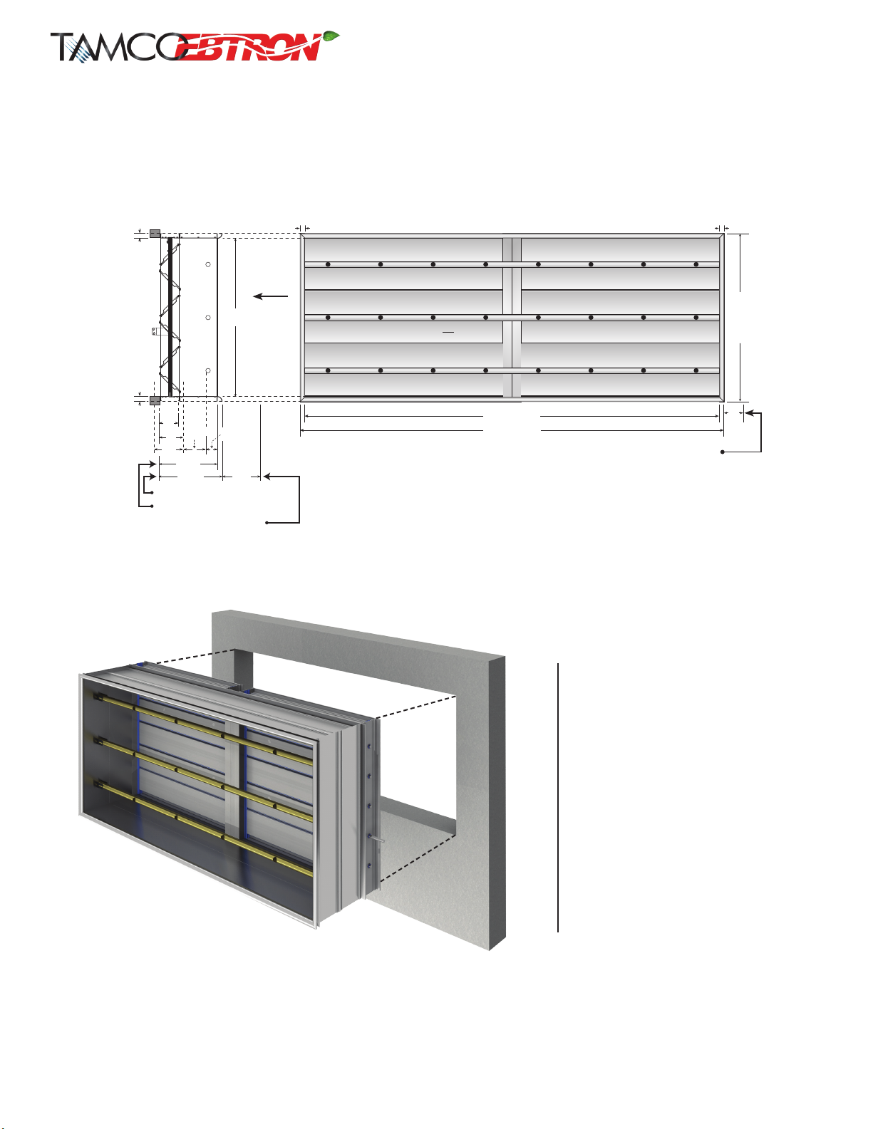
• When the AIR-IQ2 unit is viewed from damper side and labels on blades are right side up, unit orientaon is Front/Top end up.
• When viewed as Front/Top end up, right hand (RH) has drive rod as shown. Le hand (LH) has drive rod on le.
• The complete AIR-IQ2 unit can be installed vercally with the damper orientaon being right side up, or lying at.
• Ensure that the AIR-IQ2 Unit is installed allowing for future access to the EBTRON transmier, probes, damper side linkage, as well as the
damper jumper bracket.
• Duct work construcon and bracing must be sucient to support the AIR-IQ2 unit. Do not use the AIR-IQ2 unit to square up the duct. The
system must support the AIR-IQ2 unit. The AIR-IQ2 unit cannot support the system. For AIR-IQ2 units with two damper secons, ensure that
each secon is properly braced and supported.
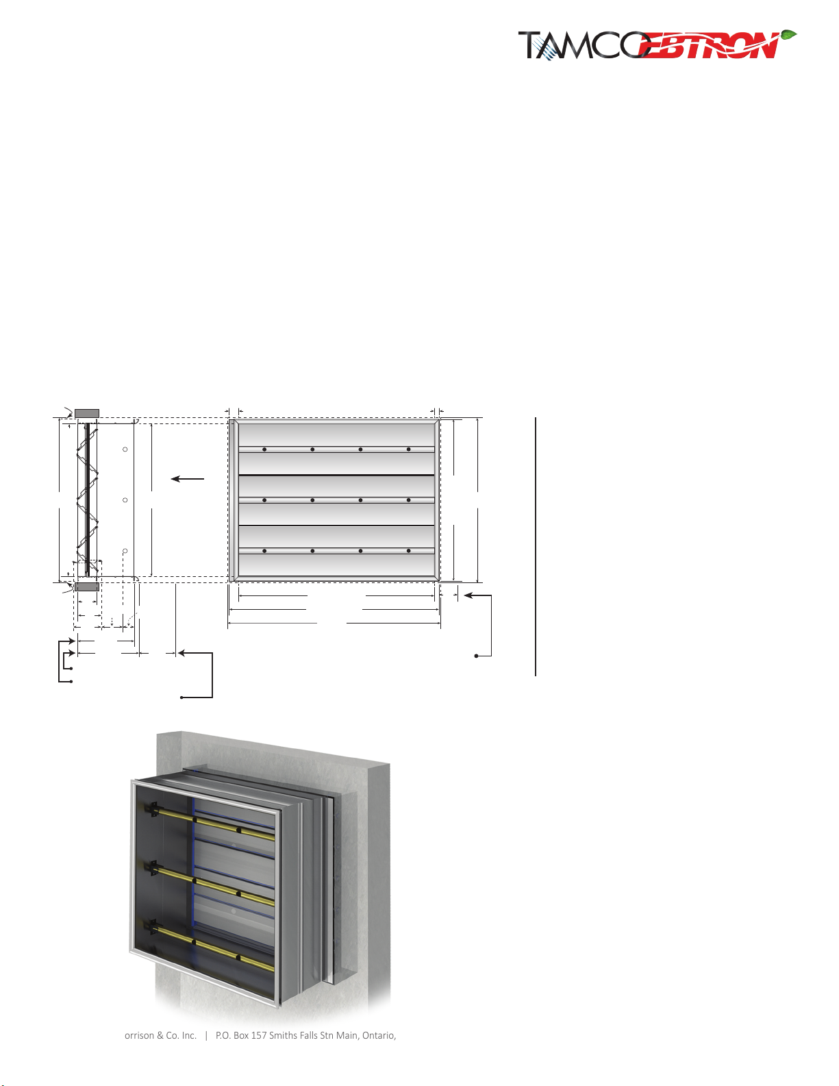
• For single-secon, vercal blade applicaons, the AIR-IQ2 unit must be installed so that the linkage and probe cables are located at the top.
• A 12" long, hexagonal steel drive rod is provided as standard. Units are shipped with the drive rod inserted in the drive blade. Drive rod may
be extended up to 8" beyond the outside edge of the frame by loosening the U-bolt, drawing out the rod to the desired length and then
reghtening the U-bolt.
• If required, 24" and 36" long zinc-plated steel drive rods can be ordered.
• Before installing, inspect the AIR-IQ2 Unit for possible damage caused in shipping.
• If minor damage has occurred to frame corners or anges, correct by bending them back into posion gently, taking care not to disturb the
EBTRON sensor probes and transmier.
• Do not install the AIR-IQ2 Unit if damage is more than supercial, if uncertain as to extent of damage, or if the damper does not seal correctly.
Call TAMCO customer service at 1-800-561-3449.
• Operate the damper secon manually (on a at secon of oor) to verify correct blade acon and sealing.
1. To correctly verify sealing acon, loosen the hex nuts of the U-bolt located on drive blade. Extend the steel drive rod to maximum of 8"
beyond the outside edge of the frame. Re-ghten the hex nuts on U-bolt.
2. Using the drive rod, slowly apply closing torque, while ensuring that the damper frame does not twist due to torque being applied. (Larger
units may require an addional person to hold the damper frame square and true.)
3. If possible, use daylight or an inside light source as a backdrop to the vericaon procedure. No light should be visible through the damper.
CAUTION SHOULD BE EXERCISED TO ENSURE FINGERS ARE NOT IN THE WAY OF MOVING LINKAGE PARTS OR BLADES.
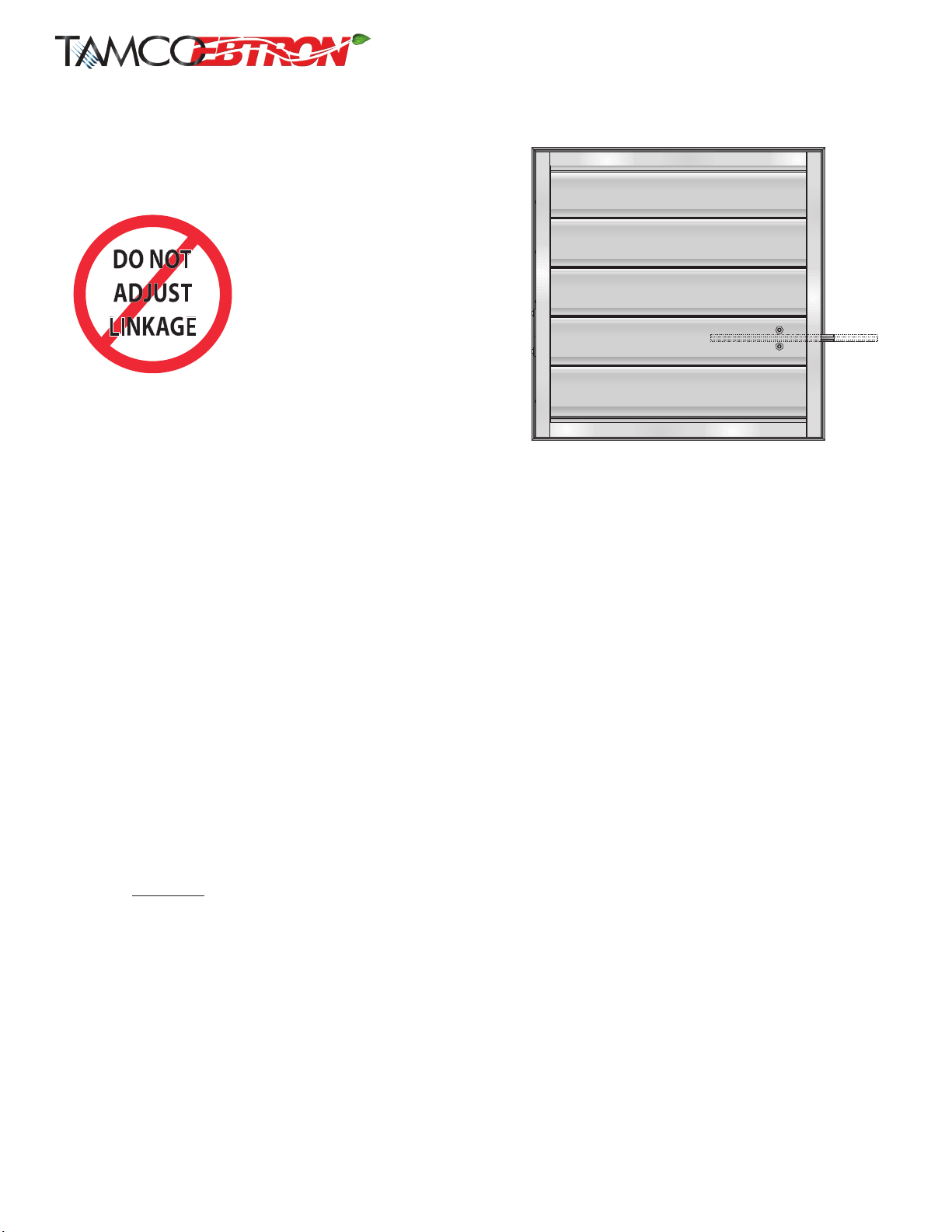
VERIFY BEFORE INSTALLATION!
FRONT / TOP END UP / RIGHT HAND
(viewed from damper side)
WARNING:
DO NOT ADJUST DAMPER LINKAGE
MECHANISM. TAMPERING WITH
LINKAGE WILL VOID DAMPER
WARRANTY. IF PROBLEM STILL
EXISTS AFTER COMPLETING PRE-
INSTALLATION VERIFICATION,
CALL TAMCO CUSTOMER SERVICE.
4
TAMCO’s all aluminum dampers are constructed with maintenance-free bearing and linkage components.
CAUTION: NEVER USE ANY LUBRICANTS, SUCH AS GREASE OR SILICONE ON TAMCO DAMPERS.
In applicaons where the humidity level is unusually elevated, or where there are extremely high levels of dust and dirt
parcles, TAMCO recommends that the damper linkage and bearing system should be cleaned once a year. This can be
done easily with the use of a domesc strength steam cleaner. The loosened dirt and water droplets can then be blown
out with compressed air.
CAUTION: TO PREVENT DAMAGE TO EBTRON SENSORS OR TRANSMITTER, NEVER APPLY STEAM, CLEANSER OR
COMPRESSED AIR TO THEM.
CAUTION: DO NOT USE PROBES AS HANDLES TO LIFT AND/OR POSITION DAMPER. DAMAGE TO THE PROBES MAY OCCUR.
⚠⚠

AIR-IQ2 AIRFLOW MEASUREMENT SOLUTION
AIR-IQ2 INSTALL GUIDE_2022_04
T.A. Morrison & Co. Inc. | P.O. Box 157 Smiths Falls Stn Main, Ontario, Canada K7A 4T1 | 800 561 3449 | Fax: 800 668 8476 | tamcodampers.com
EBTRON, Inc. | 1663 Hwy. 701 S., Loris, SC USA 29569 | 800.2EBTRON (232.8766) | Fax: 843.756.1838 | www.ebtron.com
B
+
2”
1"
1"
A*
A + 2”
4"
B*
Non-ducted applica�on
4"
5"
6"
5.1" 2.4"
12.5"
Ducted applica�on
13.5"
Minimum distance to
trailing edge of intake louver
1"
9"
BB
1"
Minimum 4" clearance for EBTRON insertion
style sensor probes and electronic actuator. Does
not include access for wiring aer installaon of
assembly. See specic EBTRON and TAMCO series
technical documentaon for more informaon.
INSIDE SLEEVE DIMENSIONS:
Parallel to blade = A
Perpendicular to blade = B
OUTSIDE DAMPER FRAME DIMENSIONS:
Parallel to blade = A + 2"
Perpendicular to blade = B + 2"
OUTSIDE FLARE DIMENSIONS:
Parallel to blade = A + 2"
Perpendicular to blade = B + 2"
*NOTES:
A x B: = Always opening dimensions
Width = A: Always dimension parallel
to blades
Height =
B: Always dimension
perpendicular to blades
AIR-IQ2 shown
with sleeve only
FLANGED TO DUCT INSTALL TYPE:
• If AIR-IQ2 unit is manufactured with the 1" are, the minimum distance from the outside edge of the are to the trailing edge of the intake louver
must be no less than 9". For opmal performance, it is recommended that the 1" are be used on ALL units where ductwork is not connected to
the leading end of the assembly.
• If AIR-IQ2 unit is manufactured as "Sleeve Only", without the 1" are, the unit may be anged to the duct, so that the minimum distance from the
outside edge of the sleeve to the trailing edge of the intake louver is a minimum of 10".
• AIR-IQ2 unit must be installed square.
• A Flanged to Duct Install Type AIR-IQ2 unit damper's nished, inside frame dimensions are equal to the specied duct or opening size.
• If the AIR-IQ2 unit is manufactured with the 1" are, the unit will be secured to the duct or opening using the damper anges only, leaving the are
side free. The overall damper frame width and height dimensions are 2" larger than the duct or opening dimensions.
• If AIR-IQ2 unit is manufactured as "Sleeve Only", without the 1" are, both sides of the unit can be secured to the duct work or openings. Both the
damper's and the sleeve's overall, outside frame/ange dimensions are 2" larger than the duct or opening dimensions.
• Do not assume that the duct or opening is square. Verify that the duct ange or hole is square, at and even.
• Verify that the unit AIR-IQ2 unit is square. Operate the damper to verify free movement of the blades and correct sealing.
• Secure the damper to the duct work or opening. Re-verify that the damper is square.
• If the AIR-IQ2 unit is manufactured as "Sleeve Only" and ducted on both sides, repeat the procedure for the other ange.
• Caulk all joints.
AIR-IQ2: TYPICAL, SINGLE-SECTION, HORIZONTAL-BLADE DAMPER
PROBES MOUNTED PARALLEL TO BLADES
FLANGED TO DUCT INSTALL TYPE
Airflow
5

AIR-IQ2 AIRFLOW MEASUREMENT SOLUTION
T.A. Morrison & Co. Inc. | P.O. Box 157 Smiths Falls Stn Main, Ontario, Canada K7A 4T1 | 800 561 3449 | Fax: 800 668 8476 | tamcodampers.com
EBTRON, Inc. | 1663 Hwy. 701 S., Loris, SC USA 29569 | 800.2EBTRON (232.8766) | Fax: 843.756.1838 | www.ebtron.com
AIR-IQ2 INSTALL GUIDE_2022_04
6
B
+
2”
1"
A + 2”
A
1"
4"
B
1"
Non-ducted applica�on
4"
5"
6"
5.1" 2.4"
12.5"
Ducted applica�on
13.5"
Minimum distance to
trailing edge of intake louver
9"
1"
AIR-IQ2: TYPICAL TWO-SECTION HORIZONTAL BLADE DAMPER
PROBES MOUNTED PARALLEL TO BLADES
FLANGED TO DUCT INSTALL TYPE
Jumpers will always be on the face of damper, downstream from the louver, and
will ship with all damper units that are two secons wide.
Minimum 4" clearance for EBTRON inseron style sensor probes and electronic
actuator. Does not include access for wiring aer installaon of assembly. See
specic EBTRON and TAMCO series technical documentaon for more informaon.
AIR-IQ2 shown with
sleeve and are
INSIDE SLEEVE DIMENSIONS:
Parallel to blade = A
Perpendicular to blade = B
OUTSIDE DAMPER FRAME DIMENSIONS:
Parallel to blade = A + 2"
Perpendicular to blade = B + 2"
OUTSIDE FLARE DIMENSIONS:
Parallel to blade = A + 2"
Perpendicular to blade = B + 2"
*NOTES:
A x B: = Always opening dimensions
Width = A: Always dimension parallel
to blades
Height =
B: Always dimension
perpendicular to blades
Airflow

AIR-IQ2 AIRFLOW MEASUREMENT SOLUTION
AIR-IQ2 INSTALL GUIDE_2022_04
T.A. Morrison & Co. Inc. | P.O. Box 157 Smiths Falls Stn Main, Ontario, Canada K7A 4T1 | 800 561 3449 | Fax: 800 668 8476 | tamcodampers.com
EBTRON, Inc. | 1663 Hwy. 701 S., Loris, SC USA 29569 | 800.2EBTRON (232.8766) | Fax: 843.756.1838 | www.ebtron.com
7
B*
B - 2.5”
1"2"
A - 0.5”
A - 3.5”
A*
B
-
0.5”
1"
¼"
1"
¼" clearance
B
Non-ducted applica�on
4"
5"
6"
5.1" 2.4"
12.5"
Ducted applica�on
13.5"
Minimum distance to
trailing edge of intake louver
9"
4"
AIR-IQ2 shown with
sleeve and are
If unit is installed with damper inserted in a wall, actuator
must be face-mounted and appropriate face-mounng
accessories will be required.
For addional details, refer to TAMCO Motor Mounng
Methods at
hp://www.tamcodampers.com/inGdeCD_motorMnt.php
INSTALLED IN DUCT INSTALL TYPE:
• If AIR-IQ2 unit is manufactured with the 1" are. The minimum distance from the outside edge of the are to the trailing edge of the intake louver
must be no less than 9". For opmal performance, it is recommended that the 1" are be used on ALL units where ductwork is not connected to
the leading end of the assembly.
• If AIR-IQ2 unit is manufactured as "Sleeve Only", without the 1" are, the unit may be inserted within the duct or in the opening, so that the
minimum distance from the outside edge of the sleeve to the trailing edge of the intake louver is a minimum of 10".
• Installaon of AIR-IQ2 unit is carried out by axing only the damper inside the duct work. Do not use sleeve or are to secure unit in duct work.
• AIR-IQ2 unit must be installed square.
• An Installed In Duct Install Type AIR-IQ2 unit damper's nished, outside frame dimensions are ½" smaller than the specied duct width and height
dimensions, to allow for clearance to insert the damper frame into the duct work.
• Ensure that the duct is square and large enough to allow the AIR-IQ2 Unit to be installed square.
• If required, make a hole in the duct work to allow extension of the drive rod.
• Verify that the AIR-IQ2 unit is square and then secure the boom damper frame to the oor of the duct using a 90° mounng angle.
• Operate the damper manually to conrm proper sealing.
• As each mounng angle is installed, verify operaon to ensure the damper is sealing correctly.
• Caulk all joints.
AIR-IQ2: TYPICAL, SINGLE-SECTION, HORIZONTAL-BLADE DAMPER
PROBES MOUNTED PARALLEL TO BLADES
INSTALLED IN DUCT INSTALL TYPE
Minimum 4" clearance for EBTRON insertion
style sensor probes and electronic actuator. Does
not include access for wiring aer installaon of
assembly. See specic EBTRON and TAMCO series
technical documentaon for more informaon.
Airflow
INSIDE SLEEVE DIMENSIONS:
Parallel to blade = A - 3.5"
Perpendicular to blade = B - 2.5"
OUTSIDE DAMPER FRAME DIMENSIONS:
Parallel to blade = A - 0.5"
Perpendicular to blade = B - 0.5"
OUTSIDE FLARE DIMENSIONS:
Parallel to blade = A - 0.5"
Perpendicular to blade = B - 0.5"
*NOTES:
A x B: = Always opening dimensions
Width = A: Always dimension parallel
to blades
Height =
B: Always dimension
perpendicular to blades

AIR-IQ2 AIRFLOW MEASUREMENT SOLUTION
T.A. Morrison & Co. Inc. | P.O. Box 157 Smiths Falls Stn Main, Ontario, Canada K7A 4T1 | 800 561 3449 | Fax: 800 668 8476 | tamcodampers.com
EBTRON, Inc. | 1663 Hwy. 701 S., Loris, SC USA 29569 | 800.2EBTRON (232.8766) | Fax: 843.756.1838 | www.ebtron.com
AIR-IQ2 INSTALL GUIDE_2022_04
8
AIR-IQ2: TYPICAL, TWO-SECTION, HORIZONTAL-BLADE DAMPER
PROBES MOUNTED PARALLEL TO BLADES
INSTALLED IN DUCT INSTALL TYPE
INSIDE SLEEVE DIMENSIONS:
Parallel to blade = A - 2.5"
Perpendicular to blade = B - 2.5"
OUTSIDE DAMPER FRAME DIMENSIONS:
Parallel to blade = A - 0.5"
Perpendicular to blade = B - 0.5"
OUTSIDE FLARE DIMENSIONS:
Parallel to blade = A - 0.5"
Perpendicular to blade = B - 0.5"
*NOTES:
A x B: = Always opening dimensions
Width = A: Always dimension parallel
to blades
Height =
B: Always dimension
perpendicular to blades
AIR-IQ2 shown with
sleeve and are
B - 2.5”
1"
¼"
1"
¼" clearance
B
Non-ducted applica�on
4"
5"
6"
5.1" 2.4"
12.5"
Ducted applica�on
13.5"
Minimum distance to
trailing edge of intake louver
9"
B*
B
-
0.5”
1"
A - 0.5”
A - 2.5”
A*
1"
4"
Minimum 4" clearance for EBTRON inseron style sensor probes and electronic
actuator. Does not include access for wiring aer installaon of assembly. See
specic EBTRON and TAMCO series technical documentaon for more informaon.
Jumpers will always be on the face of damper, downstream from the louver, and
will ship with all damper units that are two secons wide.
Airflow
STRUCTURAL DESIGN REQUIREMENTS
FOR AIR-IQ2 UNITS WITH TWO-SECTION DAMPERS
REQUIREMENTS:
• Tubular or angled steel, structural support is required to resist applied pressure loads for AIR-IQ2 units with two-secon dampers.
MAXIMUM DEFLECTION:
• The structure providing intermediate support must be designed to resist the highest pressure load, with deecon of less than L/230. This applies
whether the pressure load is created by the mechanical system, or by wind load, or if the damper is mounted on the exterior of the building.
Table of contents
Other Tamco Fire And Smoke Damper manuals
Popular Fire And Smoke Damper manuals by other brands

Trox Technik
Trox Technik FKRS-EU Installation and operating manual

Trane
Trane VariTrac VAV-SVN04A-EN Installation operation & maintenance

Mandik
Mandik FDMD installation instructions

Mandik
Mandik FDMC Series instruction manual

Trox Technik
Trox Technik FKRS-EU Supplementary installation manual

klimaoprema
klimaoprema RKP-P-N product manual