FCS-2 English
Page 21
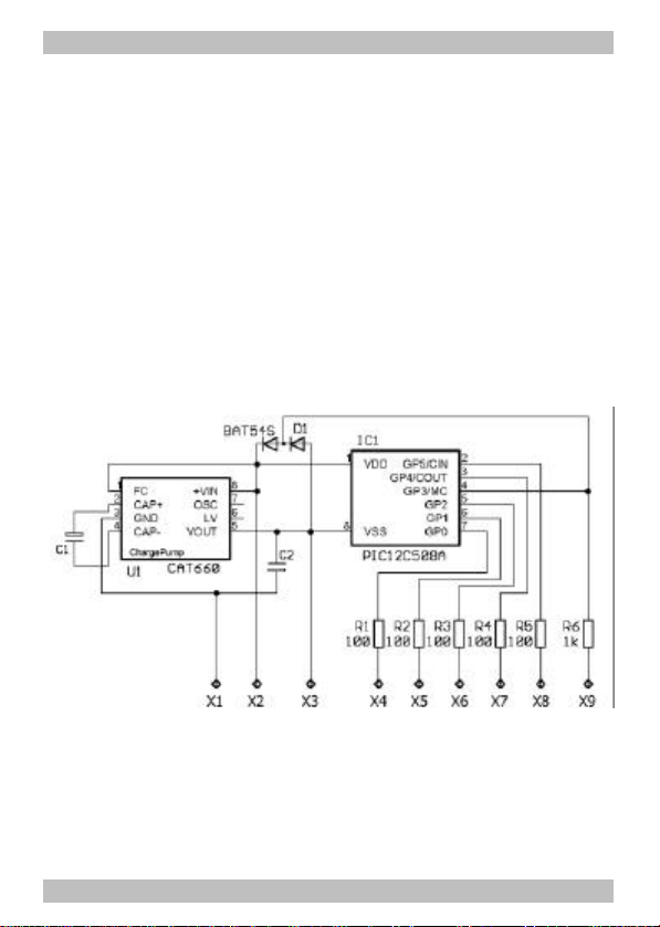
Summary of operation
The module is particularly designed for the use in vehicles compatible
to the Faller* car system, that are run with two accumulator batteries. It
has six in- and outputs for the connection of LEDs, motor, reed contacts
and a Dim switch. It is not necessary to use all outputs. The in- and
outputs are controlled from the software stored in the IC.
The voltage of 2,4 V that is provided by the vehicle accumulator batteries,
is doubled by the module. This enables white LEDs to be connected,
which normally need a voltage of more than 2,4 V. Red and yellow LEDs
may be connected directly via series resistors to the accumulator
batteries, provided they are not to be controlled by the software.
Front and back lighting
It is possible to connect two white or yellow LEDs to one output of the
module for the front lighting, and two red LEDs to another output for
the back and stop lights.
Depending on the ambient lighting, the lighting of the vehicle is
switched on and off via a light sensitive switch. The sensitivity of the
light is set via a trimpot.
While breaking and some seconds after stopping, the back lights are
switched brighter, provided that the reed contact existing in the vehicle
is connected to the module.
If the vehicle does not receive the signal to drive on for a longer time,
all lights connected to the module are switched off (current saving
mode).
Driving of the motor
The reed contact existing in the vehicle can be connected to the
module. The module then influences the motor: After a stop it starts
gently and while breaking and some seconds after stopping, the back
lights are switched brighter. If an additional reed contact is mounted,
the vehicle also brakes gently.