English FCS-4
Page 22
Other dangers
Children can cause any of the accidents mentioned above because they
are inattentive and not responsible enough. Children under the age of
14 should not be allowed to work with this module.
Little children can swallow small components with sharp edges, with
fatal results! Do not allow components to reach small children.
In schools, training centres, clubs and workshops, assembly must be
supervised by qualified personnel.
In industrial institutions, health and safety regulations applying to
electronic work must be adhered to.
EMC declaration
This product is developed in accordance with the European standards
EN 55014 and EN 50082-1, tested corresponding to the EC - directive
89/336/EWG (EMVG of 09/11/1992, electromagnetic tolerance) and
meets legal requirements.
To guarantee the electromagnetic tolerance you must take the
following precautions:
§Make no changes to the original parts and accurately follow the
instructions, circuit diagram and connections diagrams included
with this manual.
§Use only original spare parts if you have to repair module.
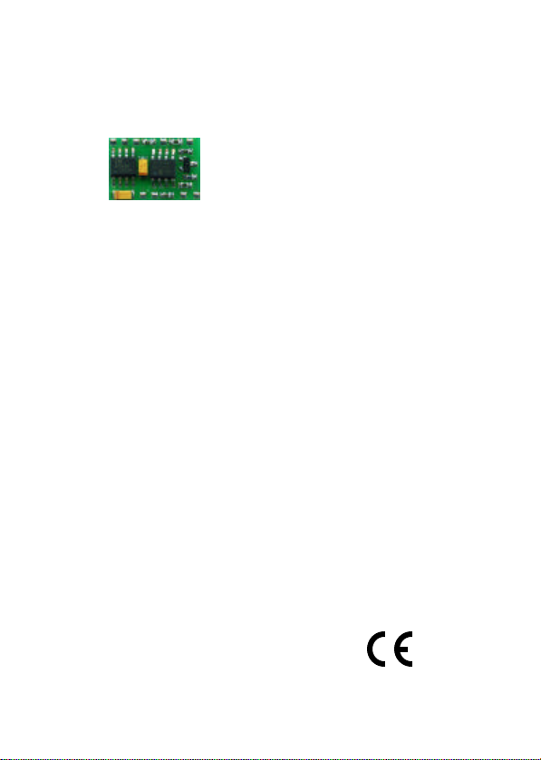
Summary of operation
The module is particularly designed for the use in vehicles compatible
to the Faller* car system, that are run with two accumulator batteries. It
has six in- and outputs for the connection of LEDs, motor, reed contact
and a loudspeaker. Additional white LEDs for the front lighting can be
connected to the additional output. It is not necessary to use all
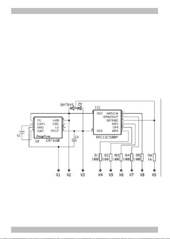
outputs. The in- and outputs are controlled from the software stored in
the IC. The software is designed for controlling an emergencyvehicle.
The voltage of 2,4 V that is provided by the vehicle accumulator batteries, is
doubled by the module. This enables white and blue LEDs to be connected,