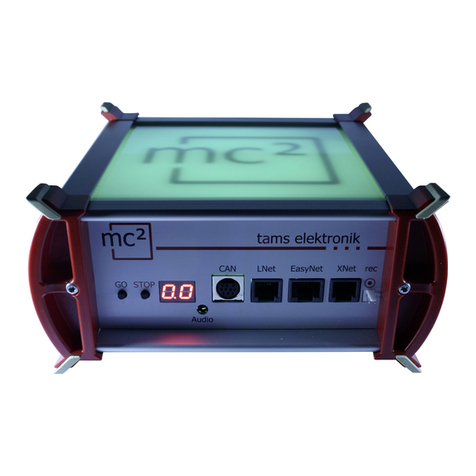
tams elektronik mc2 EasyControl Digital System Silver... User manual

Manual
Digital Control Unit for
EasyControl Digital System
Silver Edition | Item no. 40-03007
lack Edition | Item no. 40-03017
tams elektronik
n n n

Notes on this download version of the manual
This manual provides you with an overview of the features and functions of the digital central
unit mc². However, the manual is only one part of the instructions. nother essential part is
the direct help in the web interface of the central unit, the so-called mc²-Toolbox. You can
connect to a real mc² digital central unit via the Internet and test the web interface.
Link to the mc²-Toolbox
Notes for users of the digital central unit mc²
This download version of the manual may not correspond to the software and/or hardware
version of your mc². Please only use the version of the manual that is available for download
n the mc²-Toolbox.
Version 1.03 0 /2022
This manual is part of the user software "mc²-Toolbox" and applies to:
Hardware of the mc²: from Version 1.4
Firmware of the mc²: Version 1.3.0
Software for web interface mc²-Toolbox: Version 1.6.0
© Tams Elektronik GmbH
ll rights reserved, in particular the right of reproduction, distribution and translation. Copies,
reproductions and alterations in any form require the written permission of Tams Elektronik
GmbH. We reserve the right to make technical changes.
Updates
Download the latest version of the manual after you have performed an update of the mc²-
Toolbox (the software for the web interface of the mc²). ppendix B contains an overview of
the changes and additions to the manual.
Printing the manual
The formatting is optimised for double-sided printing. The standard page size is DIN 5. If you
prefer a larger display, printing on DIN 4 is recommended.
0.2 | mc²

Contents
1. Getting started........................................................................................................1.1
2. Commissioning........................................................................................................2.1
3. Your mc²................................................................................................................3.1
3.1. Display and operating elements.......................................................................3.3
3.2. Protocols........................................................................................................3.4
3.3. Virtual control devices.....................................................................................3.5
3.4. External digital input devices...........................................................................3.6
3.5. oosters.........................................................................................................3.7
3.6. PC control.......................................................................................................3.8
4. Connections............................................................................................................4.1
4.1. Main and programming track...........................................................................4.3
4.2. Connection of external digital devices...............................................................4.4
4.2.1. Devices for the CAN bus.........................................................................4.4
4.2.2. Devices for the LocoNet.........................................................................4.5
4.2.3. Devices for the EasyNet.........................................................................4.6
4.2.4. Devices for the XpressNet......................................................................4.7
4.2.5. Digital central units for DCC and Motorola...............................................4.8
4.3. Connecting iDi devices.................................................................................4.9
4.4. Connection of s88 feedback modules................................................................4.10
4.5. Connection of external boosters.......................................................................4.11
4.6. Connection to the audio output........................................................................4.12
5. Configuring the system (Submenu "System")............................................................5.1
5.1. System Info....................................................................................................5.1
5.2. Vehicles..........................................................................................................5.3
5.3. Accessories.....................................................................................................5.4
5.4. Protocol..........................................................................................................5.5
5.5. oosters.........................................................................................................5.6
6. Operation with the mc²...........................................................................................6.1
6.1. Operating and display elements.......................................................................6.1
6.1.1. STOP and GO buttons............................................................................6.1
6.1.2. Display and RG -LEDs...........................................................................6.2
Contents| 0.3

6.2. Submenu "Operation"......................................................................................6.4
6.2.1. Feedback..............................................................................................6.4
6.2.2. Programming........................................................................................6.5
6.2.3. Messages..............................................................................................6.7
6.2.4. iDi ....................................................................................................6.7
6.2.5. Control..................................................................................................6.8
6.2.6. Model time............................................................................................6.8
6.3. Virtual control devices.....................................................................................6.9
6.3.1. HandControl.vi......................................................................................6.9
6.3.2. FunctionControl.vi..................................................................................6.11
6.3.3. DriveControl.vi.......................................................................................6.12
6.3.4. SwitchControl.vi.....................................................................................6.13
7. Updates..................................................................................................................7.1
8. Checklist for troubleshooting....................................................................................8.1
8.1. Heat generation..............................................................................................8.1
8.2. Automatic safety shutdown..............................................................................8.1
8.3. Problems with the power supply.......................................................................8.2
8.4. Problems with external input devices................................................................8.2
8.5. Problems when programming and controlling vehicles.......................................8.3
8.6. Problems when switching points and other accessories......................................8.4
8.7. Problems with s88 modules.............................................................................8.4
8.8. Problems with the software update..................................................................8.5
8.9. Technical hotline.............................................................................................8.5
8.10. Repairs...........................................................................................................8.5
9. Technical data.........................................................................................................9.1
9.1. Digital control unit mc²....................................................................................9.1
9.2. Power supply unit...........................................................................................9.4
10. Warranty, EC Conformity & WEEE............................................................................10.1
10.1. Warranty Statement........................................................................................10.1
10.2. EC Declaration of Conformity...........................................................................10.2
10.3. Declarations on the WEEE Directive..................................................................10.2
Appendix A: Organisations, Manufacturers, Products..............................................................
Appendix : Changes and additions.......................................................................................
0.4 | Contents
1. Getting started
The instructions for the digital central unit mc² consist of the following parts:
the guide, which is enclosed with the delivery in printed form and which contains all the
information you need for safe and proper commissioning of the mc². The contents of the
guide are also included in this manual. Nevertheless, keep the guide carefully in case you
want to commission the mc² again and do not have access to the manual. If you pass the
digital central unit on to another person, also give the guide with it.
this manual, which is available for download in the mc²-Toolbox (the web interface of the
central unit). In the manual you will find all the information you need for safe and proper
connection to your system and external devices, as well as an overview of the configuration
of your mc² and instructions for operation. Note: The manual applies to the software
version(s) of the mc² indicated on page 0.2 of this manual.
the direct help in the mc²-Toolbox
Contents of t e package
After unpacking, check the delivery for completeness:
mc² digital control unit
power supply unit
mains cable (black) with Euro plug (CEE 7/16) and plug for mains cable socket (European
version / C7)
connection cable (grey) with RJ-45 connectors (at least Cat. 5e)
one 4-pole plug for connection to main and programming track and one 3-pole plug for
connection to external boosters
one RJ 45 blind connector (plugged into iDi connector)
4 plastic brackets for mounting the mc²
this guide and sticker sheet for labelling the connection cables
Required additional equipment
It is not possible to use the mc² digital control unit without additional devices. You can use the
following devices for commissioning, configuration and operation of the model railway layout:
Commissioning Configuration Operation
PC X X X
Tablet
(and WLAN router) X X X
Smartphone
(and WLAN router) X X
(not recommended) X
HandControl 2 --- X
(restricted) X
Other digital control
devices --- --- X
Getting started | 1.1

Intended use
The digital control unit mc² is intended for controlling digital model railway layouts according
to the information in the instructions (consisting of guide, manual and direct aids). Only the
power supply unit included in the scope of delivery is permitted for the power supply. Any
other use is not in accordance with the intended use and will result in the loss of the warranty
claim. Intended use also includes reading, understanding and following all parts of the
instructions. The mc² is not intended to be used by children under the age of 14.
Safety instructions
Improper use and non-observance of the instructions can lead to incalculable hazards. Prevent
these dangers by carrying out the following measures:
Use the digital control unit and the power supply unit only in closed, clean and dry rooms.
Avoid humidity and splash water in the environment. After condensation has formed, wait
two hours for acclimatisation before use.
Disconnect the control unit from the power supply before carrying out wiring work.
Only plug the mains plug of the power supply unit into properly installed and fused earthed
sockets.
Heating of the control unit and the power supply unit during operation is normal and
harmless. Keep a distance of at least 20 cm between the sides, the top and the back to
surrounding surfaces to allow unhindered air exchange and to predect the units from
overheating.
Do not expose the units to high ambient temperatures or direct sunlight. Observe the
information on the maximum operating temperature in the technical data.
Regularly check the operational safety of the units, e.g. for damage to the connection
cables or damage to the housing.
If you notice damage or if malfunctions occur, switch off the supply voltage immediately.
Send in the control panel and/or the power supply unit for inspection.
Dangerous voltages occur inside the power supply unit. Therefore, never open the housing
of the power supply unit.
Care
Do not use any cleaning agents to clean the mc² and the power supply unit. Only wipe the
units dry. Disconnect the units from the power supply before cleaning.
1.2 | Getting started

2. Commissioning
After commissioning, you must first configure your mc², i.e. adapt it to your ideas and adjust it
to the conditions of your model railway layout. It is therefore not recommended to start up the
mc² with a smartphone, as the display of the mc²-Toolbox (the web interface of your control
unit) is unclear due to the small screen size.
Direct connection to t e PC
You can connect your mc² directly to your PC.
Plug the (grey) patch cable on one side
into the LAN interface of the mc² and on
the other side into the RJ45 socket of the
network interface of your computer.
Connecting to t e Intranet / Internet
y connecting your mc² to your router, you can use devices such as a PC, tablet or
smartphone that also have a connection to the router to configure your mc² and control your
system. You can also use the router to connect to the Internet, which you need to check for
updates.
Plug the (grey) patch cable into the LAN
interface of the mc² on one side and into
a free RJ45 socket of the router on the
other side.
Commissioning | 2.1

!
!
Connection to t e power supply
Note:
Only use the power supply unit supplied as a power supply for your mc² and the
components of your system that are supplied by the integrated booster.
First, plug the 4-pin connector of the
power supply connection cable into the
"Power" socket on the back of the mc² so
that the flat part of the plug points
upwards.
Note:
There is a catch on the unit plug that prevents the power supply connection cable from
being pulled out accidentally. To be able to pull out the cable, you must pull the catch in the
direction of the cable. Never pull the cable out of the socket by force! Doing so may damage
connections in your mc².
Then plug the supplied (black) mains cable into the connection socket of the power supply
unit and into the socket.
Reading out t e IP address of t e mc²
Press and hold the "GO" button of the mc² until "IP" is shown in the display. If you continue
to press the "GO" key, the digits of the IP address appear one after the other. Tip: Write
down the digits including the dots.
Structure of the IP address: 123.456.789.123
Note: Leading zeros (after a dot) are not shown in the browser display.
Calling up t e IP address in t e browser
The mc²-Toolbox (i.e. the web interface of the mc²) has been tested with the browsers
Chrome, Firefox, Opera and Edge. The use of the browsers Internet Explorer and Safari is not
recommended, as they do not support all the required functions.
Enter the read IP address in the browser of the PC, tablet or smartphone. The start page
("Home") of the mc²-Toolbox will then open.
2.2 | Commissioning

User settings in t e mc²-Toolbox
Set the following on the start page of the web interface of your mc²:
longuage
Display of the submenu items: Change the display by clicking on the symbols.
Submenu items are always displayed
Submenu items are only displayed after clicking on the
higher-level main menu item.
Downloading t e manual
efore connecting the mc² to your model railway layout, download the manual from the start
page of the mc²-Toolbox ("Home") and read it carefully. In the manual you will find all the
information you need to connect to your layout and external devices, as well as an overview of
the configuration of your mc² and notes on its operation.
In the manual you will also find the troubleshooting checklist, the technical data of the control
unit and the power supply unit and the warranty declaration.
Before t e first test drive
For a first test run you can connect your mc² e.g. to a separate track oval, for which the
integrated booster is sufficient as a power supply, and familiarise yourself with the functions of
the control unit.
You have to do the following things before you can do a first round with a locomotive:
Connect the track output of the mc² to the rails (→ section 4.1 in the manual).
Configure the integrated booster, i.e. set the track voltage and the maximum current for
the nominal width of your layout (→ menu item "System / oosters").
To control a locomotive, proceed as follows:
DCC decoder: Open the virtual HandControl on the start page ("Home") of the mc²-
Toolbox. Enter the DCC address and control the locomotive. For the functionality of the
HandControl.vi → section 6.3.1 in the manual.
MM decoder: efore you can control a locomotive with the HandControl.vi, you must create
the MM address in the locomotive list and assign an MM format to the locomotive (→ menu
item "System / Vehicles").
mfx decoder: First read out the UID and assign an address to the decoder (→ menu item
"Operation / Programming / m3"). You can then control the locomotive in m3 format with
HandControl.vi.
Commissioning | 2.3

2.4 | Commissioning
Setting the display
of the submenu
Selecting
the language
Virtual
control units
(De)activating
" oredom Mode"
(De)activating
Tip of the Day
Dimming RG LEDs
(red and green only)

3. Your mc²
The main tasks of your mc² include,
to send the digital driving and switching commands to the vehicle and accessory decoders
to receive and forward the feedback signals from decoders and feedback units
to serve as a "medium" for programming the decoders.
Furthermore
a booster is integrated in your mc², which brings the digital signals to the track and
supplies the vehicles with power.
your mc² acts as an interface to various additional devices such as external input devices,
feedback devices, PC and mobile devices.
Browser-based
Your mc² uses the possibilities offered by PCs, mobile devices such as smartphones or tablets
and fast Internet in private households.
The web interface "mc²-Toolbox", i.e. the software with which you configure your digital
control and control your system, is called up via the browser of a PC, tablet or smartphone.
You then have access to all functions of the mc². The mc²-Toolbox is installed on your mc²
and you can perform updates for it in the same way as for the firmware of the central unit.
You do not need to install any software or app on your PC or mobile devices. The question of
whether the operating systems of the various devices are compatible with each other is
therefore irrelevant.
You can connect the mc² to your home network and the Internet via a router. Connection to a
Wlan router is a prerequisite for the use of mobile end devices. Alternatively, you can connect
a PC directly to your mc² (without a diversion via a router). An Internet connection is only
absolutely necessary if updates are to be requested.
T e mc² Toolbox
With the Toolbox (the web interface of the mc²) you manage your digital control including all
connected input devices, feedback devices and boosters. You can
configure your mc², i.e. adapt it to your ideas and the conditions of your layout
programme your vehicle and accessory decoders
manage your feedback devices and query messages from the various data buses ( iDi ,
s88, Märklin-CAN, LocoNet)
display RailCom messages
carry out updates
Your mc² | 3.1

Input and control devices
For the control of your layout you have various possibilities open to you, which you can also
combine with each other as you wish:
virtual control devices that you open on your smartphone, tablet or PC (→ section 3.3)
digital input devices from various manufacturers (→ section 3.4)
special PC control software (→ section 3.6)
3.2 | Your mc²

3.1. Display and operating elements
STOP & GO
These two buttons of the mc² are used
to switch the track voltage on and off
to trigger a reset
as a trigger for displaying the IP address
to delete the internal configuration
Display
The 2-digit 7-segment display shows you essential information, e.g.
the current consumption in the booster circuit of the internal booster
the operating status (short circuit, stop, normal operation)
the IP address (due to the limitation to 2 display fields in several "sequences")
the progress of an update
RGB LEDs in t e ousing
The top and bottom of the mc² are made of translucent plastic. During operation, RG LEDs
built into the housing visibly indicate the operating status of the mc² from a distance, e.g.
green for "normal operation" or red for "stop, track voltage is switched off".
Track voltage = off Track voltage = on
Your mc² | 3.3

3.2. Protocols
Digital formats
The mc² sends digital driving and switching commands to the vehicle and accessory decoders
in the following formats:
DCC: 14, 28 or 128 speed steps
Motorola: I and II (14 or 28 speed steps)
m3: This format enables the control of vehicle decoders for the mfx protocol. Note:
Automatic registration of mfx decoders with the command station is not possible.
BiDiB
The mc² is simultaneously a iDi interface and iDi track output device in the sense of the
iDi specification.
Up to 31 nodes of one level can be connected to the iDi interface of the mc². With
appropriate PC control software, digital commands can be sent and messages received and
evaluated via the iDi bus.
CAN, EasyNet and XpressNet
These protocols exclusively define the communication between input devices (e.g. hand
controllers) and the mc², but not the transmission of digital commands or feedback signals.
DCC-A
The RailCom-based extension of the DCC format according to RailCommunity standard RCN-
218 enables the automatic registration of vehicle decoders with the control centre.
LocoNet
In a later software version it will be possible to send switching commands via LocoNet and to
evaluate feedback from LocoNet. The update will be available for download free of charge.
RailCom
A global RailCom detector is integrated in the mc², which receives the messages from the
RailCom decoders and forwards them to the PC. For forwarding the RailCom messages to the
PC control software, the mc² uses the iDi protocol.
s88
Up to 52 s88 or s88-compatible modules (= 832 contacts) can be connected to the s88
interface. Note: The s88-compatible modules also include, for example, feedback devices that
are connected via the CAN bus interface.
Data transmission to t e PC
For information on the protocols used for data transmission between the mc² and the PC, see
section 3.6.
3.4 | Your mc²

3.3. Virtual control devices
From the Toolbox, you have access to various virtual control devices to control your layout.
The virtual control devices are optimised for use with smartphones or tablets, but can just as
easily be used from the PC screen.
The HandControl.vi is similar
to the real HandControl.2
and can be used to call up
vehicles and switch functions
up to F9.
With the FunctionControl.vi
locomotives can be
controlled sensitively and
functions up to F32 can be
switched.
The SwitchControl.vi is
intended for switching
turnouts (or other stationary
components). The last
locomotive called up remains
under control.
With DriveControl.vi,
4 locomotives can be
accessed simultaneously.
The speed level can be set,
the direction of travel can be
changed and the F0 function
can be switched on and off.
Your mc² | 3.5

3.4. External digital input devices
The mc² has interfaces for various digital input devices from different manufacturers. You can
integrate manual control units and/or digital control centres for the following bus systems into
your digital control:
Märklin CAN- us
LocoNet
XpressNet
EasyNet
Via the universal interface "rec" you can also integrate all digital control units for the DCC or
Motorola format that have a track output into the EasyControl system and use them as
external control and switching devices.
Possible applications for external digital input devices
Driving
(controlling vehicle
decoders)
Switching
(controlling accessory
decoders)
Programming
(programming
decoders)
Configuring
(setting up the digital
system control / mc²)
CAN X X --- ---
LNet X X --- ---
EasyNet X X X possible
(with limitations)
XNet X X X (POM only) ---
rec X X --- ---
3.6 | Your mc²

3.5. oosters
Integrated booster
A booster is integrated in the mc², which can provide a maximum of 6.5 A current. This
current is usually sufficient for the operation of layouts of all nominal sizes. Depending on the
nominal size, the maximum output current must be limited.
Short-circuit sensitivity: 1 - 6.5 A. It can be adapted to the nominal size of the installation in
steps of 0.5 A.
Track voltage: 8 - 22 V. It can be adjusted in steps of 1 V.
Track signal: symmetrical
RailCom cutout: can be switched off.
The status messages of the integrated booster are reported to the control software via iDi .
They are then available as a basis for booster management.
External boosters
If one booster circuit is not sufficient for the operation of the layout, or if the signals for
vehicle and accessory decoders are to be output separately, additional external boosters can
be connected. oth Märklin-compatible boosters and DCC-compliant boosters can be used.
The use of different booster types for separate parts of the layout or separately for the tasks
"driving" and "switching" is basically possible.
BiDiB boosters
oosters according to the iDi specification can be connected directly to the iDi interface.
Loconet boosters
oosters for use in LocoNet cannot be connected to the LocoNet interface of the mc², as this
is designed as a LocoNet T(ool) interface - and not as a Loconet (ooster) interface. No
booster signals are transmitted at the LocoNet interface of the mc². LocoNet boosters must
therefore be connected to one of the two interfaces for external boosters.
Your mc² | 3.7

Output of t e driving and switc ing commands
For the track output of the integrated booster and the interfaces for Märklin-compatible and
DCC-compliant boosters it is set separately whether
driving and switching commands or
only driving commands
are to be output. The setting for the integrated booster also applies to boosters on the iDi
interface.
3.6. PC control
Protocols: BiDiB or p50x
For the encryption of the data exchanged between the central unit and the PC control
software, the mc² uses the iDi protocol or - if this is not supported by the software - the
p50x protocol.
With software that supports iDi , all the possibilities offered by bidirectional communication
via the iDi us can be used. These include e.g.:
the direct sending of digital commands to the stationary iDi nodes via the iDi us cables
(e.g. to the accessory decoders)
receiving feedback from the stationary iDi nodes (e.g. from boosters and accessory
decoders).
the reception of messages from the global RailCom detector integrated in the mc².
If these possibilities are utilised, the safety and the transmission speed in PC-controlled
systems are significantly increased.
If the iDi protocol is not supported by the PC control software, the data transmission
between mc² and PC is automatically carried out via the p50x protocol. iDi nodes can then
not be used or only to a limited extent. iDi feedback modules are treated like s88
feedbacks, for example. The transmission of RailCom messages of the integrated global
RailCom detector to the PC control software is then not possible.
TCP to TCP
y default, the data is transmitted from the mc² to the PC or router via the LAN interface
using the network protocol TCP ("Transmission Control Protocol"). Whether the data is
encrypted in the iDi or p50x protocol is irrelevant. Many newer versions of model railway
control programs support TCP.
TCP to COM: Setting up a virtual COM port
With older model railway control programmes or older versions of the control programmes,
the data transfer between PC and digital control unit is usually based on the RS-232 standard
for serial interfaces. In most cases, these programmes use only the p50x protocol for
encoding the data.
The prerequisite for using these programmes is the setting up of a virtual serial interface (or
in other words: a virtual COM port). Various programmes are available on the internet for this
purpose, with the help of which a driver for a virtual COM port can be set up on the PC.
3.8 | Your mc²

!
!
4. Connections
Plug & Play
You can establish or interrupt connections to and from external devices to your mc² at any
time - even during operation (plug and play).
Danger of confusion!
Note that identical plug connections are used for different bus systems:
RJ12: LocoNet and XpressNet
RJ45: EasyNet, iDi , S88-N and LAN
Therefore, be very careful when plugging in the connection cables! Make sure that you do
not accidentally plug the cables into the wrong sockets! In the worst case, (even irreparable)
damage can occur to your mc² and/or the connected devices. This applies especially to
EasyNet devices, s88 modules and iDi components.
If you plug connection cables with RJ12 plugs into RJ45 sockets, the connection pins in the
socket will be bent. In this case, we recommend sending in the central unit for repair.
Avoid these risks by marking the connection cables (e.g. with the labels enclosed with the
delivery) and/or using different coloured cables for the different bus systems, e.g.
red for EasyNet
blue for the s88 bus
green for the iDi bus
grey for the Ethernet (Lan)
Bus cables
Various cable types are available for connections to RJ 12 and RJ 45 sockets:
so-called standard 1:1 cables, where the wires are connected 1:1 through and
so-called crossover cables, where the wires are connected crosswise.
Only use 1:1 cables!
Never use crossover cables for connections to interfaces with RJ-12 or RJ45 sockets of the
mc². T is can cause irreparable damage to t e control unit!
Connections | 4.1

Distributors
To enable the use of several digital control units on one interface, you can use terminal blocks
or Y-distributors:
LocoNet and XpressNet RJ12 EasyNet RJ45
Y-distributor RJ12
(item no. 73-80493-01)
Input: 1 x RJ12
Output: 2 x RJ12
Y-distributor RJ45
(item no. 73-80190-01)
Input: 1 x RJ45
Output: 2 x RJ45
XL-Terminal block (item no. 73-80496-01)
Input: 1 x RJ12 | Output: 5 x RJ12
EasyNet-Termnal block (item no. 73-80195-01)
Input: 1 x RJ45 | Output: 4 x RJ45
4.2 | Connections
This manual suits for next models
3
Table of contents
Other tams elektronik Control Unit manuals

tams elektronik
tams elektronik KSM-4 User manual

tams elektronik
tams elektronik HELIOS User manual

tams elektronik
tams elektronik LED Control Basic User manual

tams elektronik
tams elektronik 53-02015 User manual

tams elektronik
tams elektronik KSM-2 User manual

tams elektronik
tams elektronik PZS-2 Series User manual

tams elektronik
tams elektronik S88-2 User manual

tams elektronik
tams elektronik ABC-1 User manual

tams elektronik
tams elektronik PZS-3 User manual

tams elektronik
tams elektronik HADES User manual