tams elektronik KSM-3 User manual

KSM-3
Loop Module
for digital model railroad layouts
Manual
Item nos. 49-01135 | 49-0113 | 49-01137
tams elektronik
n n n

KSM-3 tams elektronik
Version: 2.0 | Status: 12/2022
© Tams Elektronik GmbH
All rights reserved, in particular the right of reproduction, distribution and translation. Copies,
reproductions and alterations in any form require the written permission of Tams Elektronik
GmbH. We reserve the right to make technical changes.
Printing the manual
The formatting is optimised for double-sided printing. The standard page size is DIN A5. If
you prefer a larger display, printing on DIN A4 is recommended.
2 | Contents

tams elektronik KSM-3
Contents
1. Getting started.............................................................................................................4
1.1. Contents of the package.......................................................................................4
1.2. Accessories..........................................................................................................4
1.3. Intended use.......................................................................................................5
1.4. Safety instructions................................................................................................5
1.5. Care....................................................................................................................5
2. Operation overview.......................................................................................................
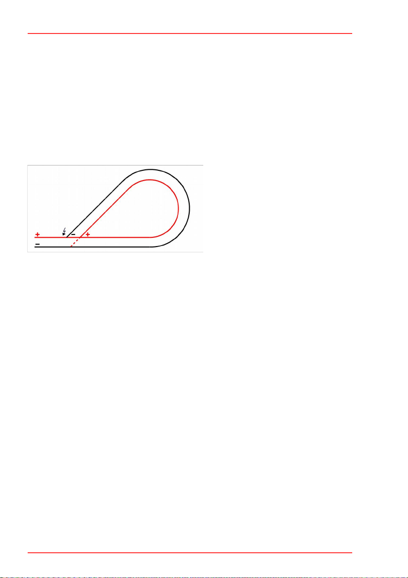
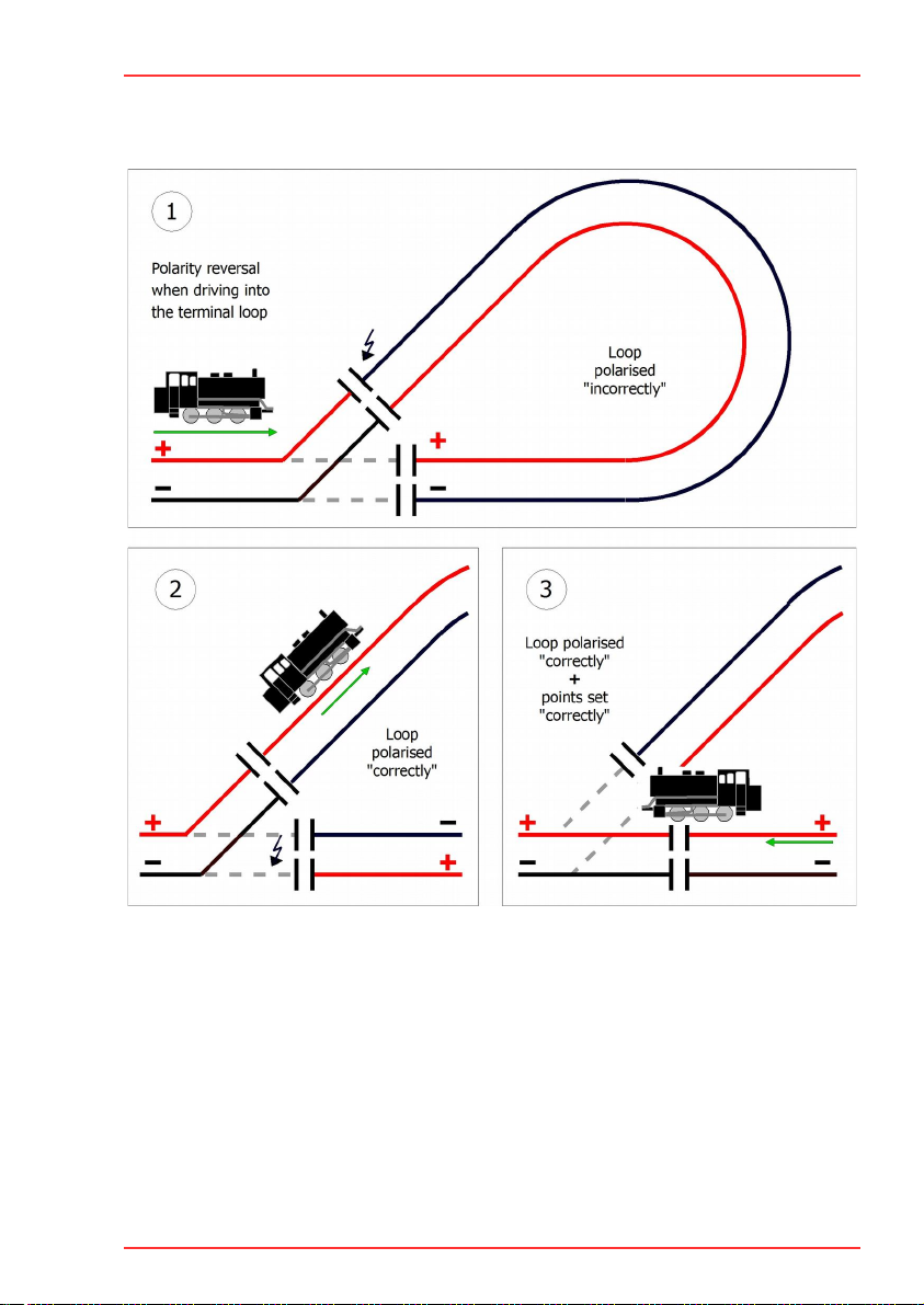
2.1. Loop problems.....................................................................................................
2.2. Mode of operation of the KSM-3............................................................................
2.3. Procedure............................................................................................................7
2.4. Designing a layout with the KSM-3........................................................................8
2.5. Use with a turntable.............................................................................................8
3. Assembling the kit........................................................................................................9
3.1. Safety instructions................................................................................................9
3.2. Soldering properly..............................................................................................10
3.3. Preparation........................................................................................................11
3.4. Assembly diagrams and parts list.........................................................................13
3.5. Assembly...........................................................................................................15
3. . Performing a visual check...................................................................................1
4. Connections KSM-3.....................................................................................................17
4.1. Isolating the terminal loop from the layout...........................................................17
4.2. Connections.......................................................................................................17
4.3. Setting the sensitivity for the polarity reversal......................................................18
4.4. Connecting a turntable........................................................................................19
5. Checklist for troubleshooting and error correction.........................................................20
5.1. Technical Hotline................................................................................................21
5.2. Repairs..............................................................................................................21
. Technical data............................................................................................................22
7. Warranty, EU conformity & WEEE................................................................................24
7.1. Guarantee bond.................................................................................................24
7.2. EU Declaration of Conformity..............................................................................25
7.3. Declarations on the WEEE Directive.....................................................................25
Contents | 3

KSM-3 tams elektronik
1. Getting started
The instructions will help you step by step with the safe and proper assembly of the kit and
installation and use of your loop module. Before you start to assemble the kit or put the loop
module into operation, read this manual completely, especially the safety instructions and the
section on possible errors and their elimination. You will then know what you have to pay
attention to and thus avoid errors that sometimes can only be rectified with a lot of effort.
Keep the instructions in a safe place so that you can restore functionality later in the event of
any malfunctions. If you pass the loop module on to another person, also give the instructions
with it.
1.1. Contents of the package
1 kit KSM-3 (item no. 49-01135-01), containing the components listed in the parts list (see
section 3.4.) and one PCB or
1 ready-built and tested circuit board KSM-3 (item no. 49-0113 -01) or
1 loop module KSM-3 in housing (item no. 49-01137-01)
1.2. Accessories
To assemble the kit ou will need
a soldering iron with temperature control and a thin tip and a deposit stand or a controlled
soldering station
a scraper, rag or sponge
a heat-resistant pad
a small pair of side cutters and wire strippers
tweezers and flat-nose pliers if necessary
electronic solder (preferably 0.5 to 0.8 mm diameter)
Connection cables
The use of stranded wire is recommended for making the connections. Stranded wires consist
of several thin individual wires and are therefore more flexible than rigid wires with the same
copper cross-section. Recommended cross-sections:
Connection of the rails:
gauges Z and N: > 0.75 mm²
other gauges: > 1.5 mm²
Connection of the points: > 0.25 mm
Connection of motor-run points
The KSM-3 has a connection to which points with double coil drive can be directly connected.
To be able to connect motor-run points, you also need an adapter:
AMW-1 (item no. 72-0007 ) or
AMW plus (item no. 72-0017 )
4 | Getting started

!
tams elektronik KSM-3
1.3. Intended use
The loop module is intended for use in model railway layouts as specified in the instructions.
Any other use is not in accordance with the intended use and will result in the loss of the
warranty claim. Intended use also includes reading, understanding and following all parts of
the instructions. The loop module is not intended to be used by children under the age of 14.
1.4. Safety instructions
Note:
The loop module contains integrated circuits (ICs). These are sensitive to electrostatic
charging. Therefore, do not touch these components until you have "discharged" yourself.
For this purpose, e.g. a grip on a radiator is sufficient.
Improper use and non-observance of the instructions can lead to incalculable hazards. Prevent
these dangers by carrying out the following measures:
Only use the loop module in closed, clean and dry rooms. Avoid moisture and splash water
in the environment. After condensation has formed, wait two hours for acclimatisation
before use.
Disconnect the loop module from the power supply before carrying out wiring work.
Supply the loop module only with extra-low voltage as specified in the technical data. Use
only tested and approved transformers.
Only plug the mains plugs of transformers into properly installed and fused earthed sockets.
When making electrical connections, ensure that the cable cross-section is sufficient.
Heating of the loop module during operation is normal and harmless.
Do not expose the loop module to high ambient temperatures or direct sunlight. Observe
the information on the maximum operating temperature in the technical data.
Regularly check the operational safety of the loop module, e.g. for damage to the
connection cables.
If you notice damage or if malfunctions occur, disconnect the connection to the power
supply immediately. Send the loop module in for inspection.
1.5. Care
Do not use any cleaning agents to clean the loop module. Only wipe the module dry.
Disconnect the loop module from the power supply before cleaning.
Getting started | 5

KSM-3 tams elektronik
2. Operation overview
2.1. Loop problems
At the loop points in two-rail-systems, different polarities meet with each other. As soon as a
vehicle bridges the differently polarized sections when driving in or out the terminal loop a
short circuit occurs.
In digital layouts loop modules generally have to adapt the polarity within the terminal loop to
the one outside. In case the polarity outside the terminal loop would be altered, different
polarities would meet with each other at the transition to the next booster section. Thus the
problem would be misaligned only.
Figure :
Short circuit problem at the loop points
2.2. Mode of operation of the KSM-3
As soon as a locomotive bridges the sectioning point between differently poled sections inside
and outside the loop, the KSM-3 changes the polarity within the terminal loop. The response
time is extremely short, as the KSM-3 already detects the voltage drop at the switchover to a
short-circuit. In consequence, the KSM-3 is able to react within milliseconds before the voltage
breaks down due to the short circuit.
The sensitivity for the polarity reversal depends on the applicated voltage and for that reason
has to be set via a trimm-pot individually. In order to allow the precise setting a LED on the
KSM-3 lights up as soon as the sensitivity has been set optimally (for the particular layout).
That way you safely prevent wheels, current collectors and rails from damages and make sure
locomotives pass the sectioning point without jerking.
Integrated switching of the points
The KSM-3 can also control the position of the points. The loop control works independently of
the points control, so that the connection of the points is not obligatory. Coil driven points
can be connected directly to the output for the points. In order to be able to use motor-run
points, an adapter for motorised turnouts AMW-1 (item no. 72-0007 ) or AMW plus (item no.
72-0017 ) is additionally required.
The points are switched automatically as soon as the locomotive reaches one of the two
sectioning points (simultaneously with altering the polarity). The two sectioning points are
assigned to a particular correct position of points. That way externally switching the points
does not interfere with the safe procedure.
| Operation overview

tams elektronik KSM-3
2.3. Procedure
Phase 1: According to the current position of points the locomotive runs clockwise or counter-
clockwise through the terminal loop. When the train is intended to run in a specific direction
through the loop, the points can be set accordingly from the outside.
Phase 2: When the train running into the loop arrives at the sectioning point behind the
points, the polarity within the loop is altered (if necessary).
Phase 3: When the train running out of the loop arrives at the sectioning point before the
points, the polarity within the loop is altered and at the same time the points are set properly
for the train to run out of the terminal loop.
Operation overview | 7

KSM-3 tams elektronik
2.4. Designing a layout with the KSM-3
The rails in the loop´s inside between the two sectioning points have to be at least as long as
the longest train to pass the terminal loop.
The circuit also works properly when there are several trains within the loop at the same time
provided that there are not two locomotives passing the sectioning points simultaneously. This
allows branching rails within in terminal loop, for example.
The maximum current of all vehicles in the loop is 8 A (including motor current of the
locomotive, carriage lighting, other accessories).
2.5. Use with a turntable
With turntables different polarities possibly meet at the transitions between bridge and the
other parts of the layout after turning the bridge. The KSM-3 can solve this problem. For that
purpose you have to connect the bridge like the loop´s inside.
8 | Operation overview

!
tams elektronik KSM-3
3. Assembling the kit
You can skip this section if you have purchased a ready-built module or device.
3.1. Safety instructions
Mechanical hazards
Cut wires can have sharp ends and can cause serious injuries. Watch out for sharp edges
when you pick up the PCB.
Visibly damaged parts can cause unpredictable danger. Do not use damaged parts: recycle
and replace them with new ones.
Fire risk
Touching flammable material with a hot soldering iron can cause fire, which can result in
injury or death through burns or suffocation. Connect your soldering iron or soldering station
only when actually needed. Always keep the soldering iron away from inflammable materials.
Use a suitable soldering iron stand. Never leave a hot soldering iron or station unattended.
Thermal danger
A hot soldering iron or liquid solder accidentally touching your skin can cause skin burns. As a
precaution:
use a heat-resistant mat during soldering,
always put the hot soldering iron in the soldering iron stand,
point the soldering iron tip carefully when soldering, and
remove liquid solder with a thick wet rag or wet sponge from the soldering tip.
Dangerous environments
A working area that is too small or cramped is unsuitable and can cause accidents, fires and
injury. Prevent this by working in a clean, dry room with enough freedom of movement.
Other dangers
Children can cause any of the accidents mentioned above because they are inattentive and not
responsible enough. Children under the age of 14 should not be allowed to work with this kit
or the ready-built module.
Caution:
Little children can swallow small components with sharp edges, with fatal results! Do not
allow components to reach small children.
In schools, training centres, clubs and workshops, assembly must be supervised by qualified
personnel. In industrial institutions, health and safety regulations applying to electronic work
must be adhered to.
Assembling the kit | 9

KSM-3 tams elektronik
3.2. Soldering properly
Use a soldering iron with temperature control, which you set to approx. 300 °C.
Only use electronic solder with a flux.
Never use soldering water or soldering grease when soldering electronic circuits. These
contain an acid that destroys components and conductor paths.
Insert the connecting wires of the components as far as possible through the holes of the
board without using force. The body of the component should be close above the board.
Make sure that the polarity of the components is correct before soldering them.
Solder quickly: soldering for too long can coffe pads or tracks to become detached or even
destroy components.
Hold the soldering tip on the soldering point in such a way that it touches the component
wire and the pad at the same time. Add (not too much) solder simultaneously. As soon as
the solder begins to flow, remove it from the soldering point. Then wait a moment for the
solder to flow well before removing the soldering iron from the soldering joint.
Do not move the component you have just soldered for about 5 seconds.
A clean, non-oxidised (scale-free) soldering tip is essential for a perfect soldering joint and
good soldering. Therefore, before each soldering, wipe off excess solder and dirt with a
damp sponge, a thick damp cloth or a silicone wiper.
After soldering, cut off the connecting wires directly above the soldering point with a side
cutter.
After assembly, always check each circuit again to ensure that all components are correctly
inserted and polarised. Also check that no connections or tracks have been accidentally
bridged with tin. This can lead not only to malfunction, but also to the destruction of
expensive components. You can re-liquefy excess solder with the clean hot soldering tip.
The solder then flows from the board to the soldering tip.
10 | Assembling the kit

tams elektronik KSM-3
3.3. Preparation
Put the sorted components in front of you on your workbench. The separate electronic
components have the following special features you should take into account in assembling:
Resistors
Resistors reduce current.
The value of resistors for smaller power ratings is indicated through colour rings.
Every colour stands for another figure.
Carbon film resistors have 4 colour rings. The 4th ring (given in brackets here)
indicates the tolerance of the resistor (gold = 5 %).
Value: Colour rings:
150 brown - green - brown (gold)
4,7 kyellow - violet - red (gold)
22 kred - red - orange (gold)
Trimm-potentiometers
Trimm-potentiometers (abrv. "trimm-pots") are resistors which allow the value of
resistance to be varied and that way to be adapted to the particular demands. In
the middle they have a small slot into which a small screwdriver can be put in
order to vary the value of resistance. The maximum value is printed on the
housing.
Depending on the mounting situation trimmpots with a lying or a standing package are used.
Ceramic capacitors
Among other things ceramic capacitors are used for filtering interference voltages
or as frequency determining parts. Ceramic capacitors are not polarized. Normally
they are marked with a three-digit number which indicates the value coded.
Number: Value:
224 220 nF
474 470 nF
Electrol tic capacitors
Electrolytic capacitors are often used to store energy. In contrast to ceramic
capacitors they are polarized. The value is given on the package.
Electrolytic capacitors are available with different voltage sustaining capabilities.
Using an electrolytic capacitor with a voltage sustaining capability higher than
required is always possible.
Diodes and Zener diodes
Diodes allow the current to pass through in one direction only (forward direction),
simultaneously the voltage is reduced by 0,3 to 0,8 V. Exceeding of the limit
voltage always will destroy the diode, and allow current to flow in the reverse
direction.
Zener diodes are used for limiting voltages. In contrast to "normal" diodes they are not
destroyed when the limit voltage is exceeded.
The diode type is printed on the package.
Assembling the kit | 11

KSM-3 tams elektronik
Light emitting diodes (LEDs)
When operated in the forward direction the LEDs light. They are available in
several different versions (differing in colour, size, form, luminosity, maximum
current, voltage limits).
Light emitting diodes should always be connected via a series resistor which
limits the current and prevents failure. In circuits to which light-emitting diodes
are connected, the series resistors are usually integrated on the circuit board.
Rectifiers
Rectifiers convert alternating into direct voltage. They have four pins: two for the
input voltage (a.c. voltage) and two for the output voltage (d.c. voltage). The
pins for the output voltage are polarized.
Transistors
Transistors are current amplifiers which convert low signals into stronger ones. There are
several types in different package forms available. The type designation is printed on the
component.
Transistors for a low power rating (e.g. BC types) have a package in form of a
half zylinder (SOT-package).
Transistors for a high power rating (e.g. BD types) have a flat package (TO-
package), which is in use in different versions and sizes.
The three pins of bipolar transistors (e.g. BC and BT types) are called basis,
emitter and collector (abbreviated with the letters B, E, C in the circuit diagram).
Integrated circuits (ICs)
Depending on the type, ICs fulfil various tasks. The most common housing form
is the so-called "DIL"-housing, from which 4, , 8, 14, 1 , 18 or more "legs"
(pins) are arranged along the long sides.
ICs are sensitive to damage during soldering (heat, electrostatic charging). For
that reason in the place of the ICs IC sockets are soldered in, in which the ICs
are inserted later.
Microcontrollers
Microcontrollers are ICs, which are individually programmed for the particular application. The
programmed controllers are only available from the manufacturer of the circuit belonging to it.
12 | Assembling the kit

tams elektronik KSM-3
Rela s
Relays are electronic switches, depending on their position the one or other (internal)
connection is closed. The mode of operation of monostable relays can be compared to that of
a push-button switch, i.e. the connection is only closed as long as the voltage is applicated.
Bistable relays keep their status after switching – comparable to a switch.
Relays which combine two switches in one housing are common as well (shortly 2xUM). The
switching between the two connections can be heard clearly because of the resulting clicking
sound.
Screw terminals
Screw terminals provide a solder-free and safe connection of the cables to the circuit, which
can still be separated any time.
Terminal strips are available as single or double row versions with 2 or 3 poles (resp. 2x2 or
2x3 poles). Connections with any number of poles can be created by linking several terminal
strips. In order to fix them the connecting cables are inserted and screwed (similar to a lustre
terminal).
Plug-in units consist of a 2-, 3-, 4- or more pole box header to be soldered on the PCB and an
appropriate plug-in part into which the connecting cables have to be inserted and srewed.
3.4. Assembly diagrams and parts list
Assembl diagram hardware version 1 Assembl diagram hardware version 2
Assembling the kit | 13

KSM-3 tams elektronik
Parts list
Resistors R5 150
R2, R3, R4, R , R7, R9 4,7 k
R1 22 k
Trim pots R8 10 k (standing)
Diodes D1, D2, D3, D , D7 1N400x, x=2...7
Zener diodes D4 5V
LEDs D5 3 mm (green)
Rectifiers D1-4 B80C1500
(or similar)
Capacitors C3 220 nF
Hardware version 2 only: C 470 nF
Electrolytic capacitors C5 2,2 µF / 25 V
C1, C2 100 µF / 25 V
C4 220 µF / 25 V
Transistors Q2 BC337
Q1 BC547B
T1, T2 BD 79
Micro-Controllers IC1 PIC12F1571-I/P
IC-sockets IC1 8-pole
Relais K1 2xUm, 8 A, 5V
monostable
Terminal strips X1, X2 1x2-pole
Plug-in units S2 3-pole box header
3-pole plug-in part
14 | Assembling the kit

!
tams elektronik KSM-3
3.5. Assembly
Proceed according to the order given in the list below. First solder the components on the
solder side of the PCB and then cut the excess wires with the side cutter. Follow the
instructions on soldering in section 3.2.
Caution:
Several components have to be mounted according to their polarity. When soldering these
components the wrong way round, they can be damaged when you connect the power. In
the worst case the whole circuit can be damaged. At the best, a wrongly connected part will
not function.
1. Resistors Mounting orientation of no importance.
2. Diodes, Zener diodes Observe the polarity!
The negative end of the diodes is marked with a ring. This is
shown in the PCB layout.
Solder the diode D and D7 that way, their bodies are
standing upright on the PCB.
3. Ceramic Capacitors Mounting orientation of no importance.
4. IC sockets Mount the sockets that way, the markings on the sockets
show in the same direction as the markings on the PCB
board.
5. Transistors Observe the polarity!
The cross section of transistors for a low power rating in
SOT-packages is shown in the PCB layout.
With transistors for a high power rating in TO packages (e.g.
BD types) the unlabelled back side is marked in the PCB
layout by a thick line.
. Rectifiers Observe the polarity! The pin connections are printed on the
housing. The longer connecting pin is the positive pole.
7. Electrolytic capacitors Observe the polarity! One of the two leads (the shorter one)
is marked with a minus sign.
8. Relays The mounting orientation is given by the layout of the pins.
9. Light emitting diodes
(LEDs)
Observe the polarity!
With wired LEDs the longer lead is always the anode
(positive pole).
10. Srew terminals Terminal strips and box header of the plug-in unit.
11. Trimm-potentiometers The mounting orientation is preset by the layout of the three
pins.
Assembling the kit | 15

KSM-3 tams elektronik
12. ICs in DIL-housing Insert the ICs into the soldered socket.
Do not touch the ICs without first discharging yourself by
touching a radiator or other grounded metal parts.
Do not bend the "legs" when inserting them into the sockets.
Check that the markings on the PCB, the socket and the IC
show to the same direction.
3. . Performing a visual check
Perform a visual check after the assembly of the module and remove faults if necessary:
Remove all loose parts, wire ends or drops of solder from the PCB. Remove all sharp wire
ends.
Check that solder contacts which are close to each other are not unintentionally connected
to each other. Risk of short circuit!
Check that all components are polarised correctly.
When you have remedied all faults, go on to the next part.
1 | Assembling the kit

tams elektronik KSM-3
4. Connections KSM-3
4.1. Isolating the terminal loop from the layout
First isolate the loop completely from the rest of the layout. Arrange the two isolating points
as near to the points as possible.
4.2. Connections
There are two terminal strips for the connection of the rails and a plug-in unit (consisting of a
box header and an appropriate plug-in part) for the connection of the points soldered to the
module which are used to insert and screw on the connecting wires.
Connections KSM-3 | 17

KSM-3 tams elektronik
Terminal assignment
X1 Inside of the loop
1 → inner rails
2 → outer rails
X2 Layout outside the loop
1 → inner rails
2 → outer rails
X3 Optional: coil driven points (or motor-run points with additional adapter AMW-1 or
AMW plus)
1 →Position of points 1
2 →Voltage supply / Return conductor
3 →Position of points 2
Connecting points
Connecting points to the KSM-3 is optional. You can do without when you do not intend to
switch the points automatically.
Each of the two isolating points is assigned firmly to one position of points. If the position is
"branch" or "straight" depends on the particular mounting situation.
For that reason you have to check after having connected them if the points switch
"correctly", when the locomotive passes the isolating points on its way out of the loop. If not,
you have to interchange the connections of the points (X3-1 and X3-3).
4.3. Setting the sensitivity for the polarity reversal
Proceed accurately when setting the sensitivity for the polarity reversal in order to make sure
the KSM-3 already reacts at the beginning of the voltage drop and alters the polarity within
the loop as quickly as possible. If the inevitably occuring short circuit lasts too long, wheels,
rails and current collectors possibly corrode or locomotives passing the sectioning point
possibly jerk. With a very high current the short circuit interruption of the booster possibly
reacts.
First set the trimm-pot by use of a small screwdriver as far to the left as possible. Then turn it
1. slowly to the right, until the LED lights up or flashes
2. further to the right, until the LED goes out or the relay switches (audible by a
clicking sound)
3. carefully back to the left, until the LED lights up or flashes again or the relay stops
to switch
18 | Connections KSM-3

tams elektronik KSM-3
4.4. Connecting a turntable
You can use the KSM-3 in combination with a turntable.
X1 Rails of the bridge.
The assignment of the connections 1 and 2 is of no importance.
X2 Rail output of the booster
1 → connection for "inner" rails
2 → connection for "outer" rails
Connections KSM-3 | 19

!
KSM-3 tams elektronik
5. Checklist for troubleshooting and error correction
Warning: If you notice a strong heat development, immediately disconnect the
connection to the supply voltage. Fire hazard!
Possible causes:
One or more connections are faulty. à Check the connections.
"Kit" version: one or more components are soldered incorrectly. à Carry out a visual
inspection (à section 3. .) and eliminate the faults, if necessary.
The current consumption of the vehicles in the terminal loop exceeds 8 A. à Reduce the
current consumption.
The module is defective. à Send the feedback module in for inspection.
When setting the trimming pot the rla does not switch.
Possible causes:
"Kit" version: One or more components are soldered incorrectly. Perform a visual check.
"Kit" version: The IC has been inserted into the IC-socket in the wrong direction. The IC
has consequently been destroyed and must be replaced. (The programmed IC can only be
purchased directly from Tams Elektronik!)
During operation the central unit switches off.
Possible causes:
"Kit" version: One or more components are soldered incorrectly. Perform a visual check.
The trimming pot is set incorrectly. Set the trimming pot according to the section
"Setting the operating point" and repeat the test.
When the train is driving out of the loop the points are switched incorrectl .
Possible causes:
The connections X3-1 and X3-3 have been assigned incorrectly. Interchange the
connections.
When switching the points, a short circuit occurs, possibl the points clatter.
Possible causes:
The current needed to switch the points is higher than 1 A. Solder a choke (e.g. 3,3 µH)
into the conductor to the points´voltage supply (middle connector).
20 | Checklist for troubleshooting and error correction
Table of contents
Other tams elektronik Industrial Equipment manuals
Popular Industrial Equipment manuals by other brands

Kobelt
Kobelt 7166 Electric Helm Owner's Operation, Installation & Maintenance Manual

Reliable
Reliable DDX PrePaK Installation, operation and maintenance manual

Premier
Premier 2200PK-ELL Service guidelines

Sunrise
Sunrise IW-45M instruction manual

SPEWE
SPEWE 43cm type III quick start guide

Warner Electric
Warner Electric PB-825 installation instructions