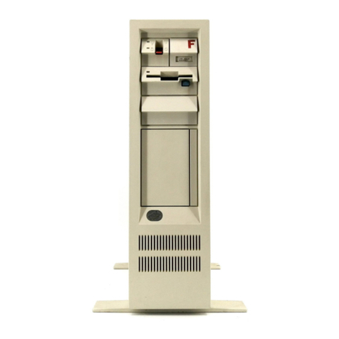
Tandy 1000 SL Product manual


The Technical Reference Manual for the Tandy
1000
SL
describes the
computer hardware components and their relationships to one another,
as
well
as the BIOS
(Basic
Input Output Services).
The information in this manual
is
intended for hardware and software
designers, engineers, programmers, and anyone who requires an
understanding of the design and operation of the computer.
Timing diagrams for devices used in the system architecture, Schematics,
specifications, switch settings and jumpers, and a theory of operation
are provided for the following hardware sections:
Main Logic Board
Devices
Power Supplies
Keyboards
Disk
Drives
The Software section contains the following:
A
Quick Reference
list
of software interrupts
(for
all
device,
I/O,
and system status services)
Keyboard ASCII and scan codes
An MS-DOS memory map
The information in this manual
is
a
supplement to and based on
a
working
knowledge of the following literature:
The
1000
SL
Installation and Operation Guide (Packaged with th
compute
r
)
The Intel iAPX 86/88/186/188 User's Manual-Programmers
Reference. Intel order number 210911-003
The Intel iAPX 86/88/186/188 User's Manual-Hardware Reference.
Intel order number 210912-001
AP-67 8086 System Design. Intel order number 230792-001
This Intel literature may be ordered directly from Intel
at
the followin
number: 1-800-549-4725

Tandy
lOOOSL
Page Insertion Guide
Important Customer Note:
A gray stripe has been printed along the right edge of the
title page of each of the sections to facilitate your
finding the beginning of the section.
Also,
a tabbed divider for each section has been provided
for
.
insertion at this point.
Exploded view: Insert at the end of the Assembly/Dis-
assembly section
Foldout schematic pages: Insert at the end of the Main
Logic Board section
Schematics
Schematic
C8000302
-
Rev B
Sheets
1
of 7 thru 7 of 7
C8000308
-
Rev B
Sheet
1
of
1
Foldout PCB art: Insert after the Main Logic Board
schematics
Silkscreen 1700378
-
Rev B
Layer
1
Component Side
Layer 2 GND Plane
Layer 3
+
5V Plane
Layer 4 Solder Side
Foldout schematic page: Insert at the end of the 67
Watt Single Input Power Supply section
Schematic Model No. 8790085
Foldout schematic page: Insert at the end of the 67
Watt Dual Input Power Supply section
Schematic Model No. 8790084
Foldout keyboard art pages: Insert after the Fujitsu
Keyboard information in the Keyboard section
Keyboard Unit Assembly N860-47
0
340
0
1
circuit Specification N86C-4700-0001
circuit Specification N86C-4700-0101
Block Diagram 4700

Foldout schematic page: Insert after the Fujitsu custom
IC Pin Signal sheet
2
of
3
in the Keyboard section
Schematic Fujitsu Custom IC Pin Signals
&
Function
Sheet
3
of
3
Foldout TEAC schematic pages: Insert after the Section
3
-
Maintenance portion
of
the Disk Drive section
PCBA Front Opt
#N
Total Diagram
PCBA MFD Control
#N
FD-55R
FD-55BR/FR/GR
Sheets
1
of
3
thru
3
of
3
FD-SsBR/FR/GR
Sheets
1
of
2
thru
2
of
2

Table
Of
Contents
Introduction
1
General Description
1
Specifications Summary
2
Optional Features
2
System Assembly/Disassembly (Including Exploded Views)
3
Main Logic Board
5
I
ntroduct
i
on
5
Switch Settings and Jumper Pin Configurations
6
Theory of Operation
7
8086
Microprocessor
7
8087
Numerical Math Coprocessor
7
Clock Generation
7
Command and Control Signal Generation
8
DRAM Control
9
Refresh Control
9
BIOS ROM Control
10
Reset Circuit
10
Wait State and Ready Logic
10
NMI Logic
12
8087
Control Logic
12
CPU Address Buffers
12
Data Buffers and Conversion Logic
12
1/0
Decode
13
Floppy Disk Controller
13
Interrupt Controller
14
video controller
15
Timer
16
Joystick Interface
16
Keyboard Interface
17
Sound Circuit
17
Additional Sound Features (DAC)
17
DMA Controller
18
RS232
Serial Port Interface
18
Parallel Printer Port Interface
19
Expansion Ports
20
System Expansion Bus
20
Expansion Bus Signal Description
21
Memory Map
23
1/0
Port Map of System
24
1/0
Port Map Summary
24

In
t
rod
uc
t
io
n

Introduction
General Description
The Tandym
1000
SL
is
modular in design
to
allow
maximum
flexibility in system configuration. The computer consists of
a
main unit, and
a
detachable keyboard with coiled cable. The main
unit
is
supplied with one internal Sf-inch
360K
floppy disk
drive. The standard types of monitors used with the Tandy 1000
SL
are
the monochrome and the
color
RGB
monitor. Since these units
are
modular, you can place them on top of the main unit
or
at
any
convenient location.
The Tandy
1000
SL
comes
standard with
384K
of system
RAM.
An
optional
256K
RAM
can be added on the system board
to
expand the
memory
to
a
full
640K
bytes, the maximum
RAM
allowed by the
system memory map.
Other features include
a
parallel printer port,
a
serial
port,
two
built-in joystick interfaces,
a
speaker for audio output,
a
microphone jack, and
a
headphone jack with volume control.
1

Specifications Summary
.
.
8086
CPU
running
at
8 MHz,
0
wait
state,
switchable
to
4
MHz
Socket for 8087 numerical coprocessor
384K bytes
DRAM
upgradeable
to
640K bytes (16-bit data bus)
4
Mbit
BIOS
ROM
with MS-DOS@ and Deskmate@ (16-bit data bus)
Tandy 1000
SL
video controller that supports:
-
128K bytes
DRAM
(used
as
system and video memory)
-
alphanumeric mode
-
graphics modes including:
-
160
X
200 16-color
-
320
X
200
4-COlOr
-
320
X
200 16-color
-
640
x
200 2-color
-
640
X
200
4-COlOr
8237-5
DMA
controller that supports:
-
3
DMA
channels
-
8-bit transfers
-
4
MHz clock speed
8259A interrupt controller for 8 interrupts
8254 interval
timer
that supports:
-
system interrupt timing
-
sound timing
Custom keyboard interface controller
101-key Enhanced keyboard
Custom parallel printer port
Serial port (RS-232-C)
Audio interface circuit that supports:
-
internal 8-OHM speaker
-
headphone jack with user accessible volume control
-
microphone input
Joystick interface for
two
joysticks
Custom floppy disk controller circuit that supports:
-
5f-inch 360K floppy disk drives
-
33-inch 720K floppy disk drives
One 5f-inch 360K floppy disk drive
Five 10" 8-bit expansion
slots
Reset
button and support logic
67-Watt power supply
Optional Features
.
Real-time
clock w/battery
8087 numerical math coprocessor
256K
DRAM
upgrade (16-bit data bus memory)
Sf-inch 360K floppy disk drive
33-inch 720K floppy disk drive
Add-in hard disk drives
Hard disk card (20/40 meg)
Display adapter boards that support mono,
EGA,
or
other
special video modes
300,
1200,
or
2400 baud modem boards
2

Assembly/Disassembly

System Assembly/Disassembly (Including Exploded Views)
The following instructions explain how the major subassemblies
are removed from the Tandy 1000
SL.
Re-assembly of major sub-
assemblies is accomplished by reversing the order of the removal
procedures.
1.
Top Cover Removal
a. Remove the
(2)
screws from the side of the computer at the
rear.
b. Slide the cover forward enough to clear the power button,
volume knob, and disk drive eject button and off.
2.
5)-inch Floppy Drive Removal
a. Remove the top cover.
b. Unplug all cables from the disk drive.
c. Remove the
(3)
screws attaching the drive to the drive
mounting tower.
d. Slide the drive forward out of the drive mounting tower.
3.
Power Supply Removal
a. Remove the top cover.
b. Remove the rear panel by slightly bending the hooks on each
side near the bottom and rotating enough to clear the sheet
metal and then lift up.
c. Remove all cables from the main logic board and disk drives.
d. Remove the arm attached
to
the power supply switch.
e. Remove the
(2)
screws from the rear of the computer and
(1)
screw from the side that secure the power supply to the rear
of the machine.
f.
Slide the power supply up and out.
3

4.
Main Logic Board
Removal
a.
Remove the
top
cover.
b. unplug
all
cables
and
remove
all
the adapter boards
from
the
system.
c.
Remove
the
power
supply.
d.
Remove
the back
of
the chassis by removing
(2)
screws
at
the
rear
of the
computer
and pulling the back of the chassis
to
the
rear
and down
to
clear
the
(3)
hooks
in
the
bottom
of
the chassis.
e.
Remove spring
clip
from volume control knob
post.
f.
Remove the
(11)
screws
holding the main
logic
board in
place.
g.
Remove
the
main
logic
board by carefully pulling straight
back from under the drive support and out of the chassis.
NOTE: WHEN REPLACING THE
MAIN
LOGIC BOARD, BE SURE THAT THE
VOLUME CONTROL KNOB POST SLIDES INTO THE VOLUME CONTROL
POT CORRECTLY.
4

QTY.
1
5
5
4
4
1
1
11
4
4
1
1
1
3
1
4
1
1
1
2
1
1
1
1
1
2
1
2
1
4
1
2
1
1
3
1
2
2
2
1
1
1
4
DESCRIPTION
CHASSIS
-
WELDMENT
PANEL
-
OPTION SLOT
SCREW
-
#4-40
X
3/16
FOOT
RIVET
-
#1661-0512
PC BOARD
-
MAIN LOGIC
PC BOARD
-
FRONT
&
BACK (BREAK APART BD)
SCREW
-
#6-32
X
1/4
JACKNUT
-
#4-40
X
3/16
SHIELDING STRIP
KNOB
-
VOLUME CONTROL
CLIP
-
HAIRPIN
CHASSIS
-
POWER SUPPLY
SCREW
-
#6-32
X
5/16
POWER SUPPLY
-
67
WATT
INT' L
DOM.
DOM.
SCREW
-
#6-32
X
5/16
DC HARNESS
SWITCH
-
POWER
SWITCH
-
POWER
INT'L
SCREW
-
M3
X
5
PPH
BUTTON
-
POWER
ACTUATOR
-
POWER SWITCH
RECEPTACLE
-
AC
HARNESS
-
AC
HARNESS
-
AC INT'L
CAPACITOR
-
1000
PFD,
400V
TORROID
-
CORE FAIRRITE
NUT
-
KEPS,
#6-32
FAN
-
80MM;
12
VDC
SCREW
-
#lo
TAPIT THREAD
ENDPLATE
-
POWER SUPPLY
SCREW
-
#6-32
X
5/16
CHASSIS
-
REAR
DISK DRIVE
-
5 1/4"
TEAC
SCREW
-
M3
X
5
PPH
CABLE
-
SIGNAL
RAIL
-
5 1/4"
DRIVE
CLIP
-
GROUNDING, DRIVE
SCREW
-
#6
-
32
X
1/4
PHILLIPS PAN
HD
BRACKET
-
HARD CARD
SCREW
-
#6-32
X
5/16
SPEAKER W/CABLE
SCREW
-
#6-32
X
5/16
PART
NUMBER
8729709
8729562
8569333
8590179
8565014
8859024
8859110
8569326
8569341
8729658
8719624
8559080
8729690
8569339
8790084
8790085
8790091
8569339
8709857
8489111
8489112
8569293
8719625
8719620
8519246
8709868
8709873
8352106
8419030
8579004
8790424
8569301
8729691
8569339
8729693
8790136
8569293
8709856
8719603
8529064
8569098
8729704
8569339
8490013
8569339

MECHANICAL BILL OF MATERIAL
-
TANDY
1000
SL
TANDY
1000
SL FINAL ASSEMBLY
QTY.
1
1
2
5
1
4
1
1
1
1
1
1
1
1
1
1
1
1
1
-
DESCRIPTION
PANEL
-
REAR
BEZEL
-
FRONT
PIN-GU IDE
SCREW
-
#6
X
3/8
CASE
-
TOP
SCREW
-
#lo-24
UNC
X
3/8"
PHILLIPS OVAL HEAD MACHINE SCREW
BUTTON
-
RESET, FRONT
BUTTON
-
RESET, REAR
SPRING
-
RESET BUTTON
CORD
-
POWER
18/3
60/C
LABEL
-
SERIAL, CSA
NAMEPLATE
LABEL
-
SERIAL, INT'L
LABEL
-
SERVICE ADVISEMENT
(6
LANG)
LABEL
-
CAUTION
(6
LANG)
LABEL
-
EARTH GROUND INT'L
LABEL
-
VIDEO, MONOCHROME COMMAND
KEYBOARD ASSEMBLY
LABEL
-
SERIAL
UL/FCC,
PART
NUMBER
8719602
8719598
8739038
8569294
8729686
8569354
8719440
8719441
8739018
87891644
8709057
87891645
8719618
87891646
87891571
87891572
87891253
87891648


Main Logic Board
Introduction
The main unit is the heart of the Tandy
1000
SL.
It houses the
main logic assembly, system power supply, and floppy disk drive.
The main logic assembly is a large board mounted to the bottom of
the main unit and interconnected to the keyboard, power supply,
and disk drive by a series of cables.
The power supply is a
67W
switching regulator type, designed to
provide adequate power capacity for a fully configured system
that has all the option slots in use.
The floppy disk drive uses 54-inch double-sided, double-density
diskettes to read, write, or store data. These are soft sector
diskettes. The disk drive assembly comes installed in the main
unit.
All
system programs, with the exception
of
the system
startup sequence, are stored on diskette.
5

Switch Settings and Jumper Pin Configurations
Main Logic Board
Jumper Function
E1-E2 Select
video
Interrupt
on
IRQ5
E2-E3
Normal
Video Interrupt
Sound Input/Output Satellite Board
Jumper Function
El-E2
E2-E3
Select
Direct
Line
Audio Input
Select
Mic
Audio
Input
Default
E2-E3
Default
E2-E3
6

Theory
of
Operation
8086 Microprocessor
The 8086 (U29) is a high-performance 16-bit microprocessor with
internal and external 16-bit data paths, one megabyte of memory
address space, and 64K of 1/0 address space. The 8086
communicates with the rest of the system via a 20-bit multiplexed
address/data/status bus and a command bus.
8087 Numerical Math Coprocessor
The 8087 (U21) performs high-speed arithmetic and logarithmic
functions and trigonometric operations that increase the
performance of an 8086 system. Performance increases are obtained
by the 8087's ability to perform math calculations faster than
the 8086, and also by executing math instructions in parallel
with the 8086.
Clock Generation
Clocks required by the system are generated by TTL oscillator Y2,
Y1
and the custom IC 8079024 (U41). There are two independent
clock circuits supplied by a Dual Oscillator Clock (Y2,Yl) from
which all other clocks, excluding video clocks, are derived.
The 24 MHz Clock is routed into the custom IC 879024, which
generates the output signal CPUCLK. The Clock Switch circuitry
required to toggle the 8086 Microprocessor between 8 MHz and 4
MHz mode, as well
as
the logic to prevent any short cycling
during a clock switch cycle, are implemented in the custom IC
879024 IC. If Bit
3
is asserted during an 1/0 write to Port 062
(hex), then the output signal CPUCLK operates the 8086 in 8 MHz
mode. If Bit
3
is negated
low
during an 1/0 write to Port 062
(hex), the output signal CPUCLK operates the 8086 in the 4 MHz
mode. When Reset is generated, the signal RESET is asserted and
defaults the Tandy
1000
SL
to the 4 MHz mode.
The custom IC 879024 Chip also controls wait states to insert the
proper number of wait states required for a two clock mode of
operation. Zero to three wait states are inserted in all 8-bit
Memory and 1/0 cycles, in both 8 MHz and 4 MHz modes. These wait
states are separately programmable. During all 16-bit memory
cycles, either zero or one wait state
is
inserted in both the
8 MHz and 4 MHz modes. These values are programmable and will be
discussed later in the section "Wait State and Ready Logic".
7

Command and Control Signal Generation
The command and control signals required for the Tandy
1000
SL
operation
are
generated by the 8079024 custom
IC.
The
command signals
are
decoded from the CPU status signals
SO-
through
S2-
during the
TS
cycle. The decoded signals indicate the
type of cycle that
is
to
be executed (MEMR-, MEMW-,
IOR-,
IOW-,
INTA-). The control signals CPUALE, BUSALE control the
external
latching of addresses onto the bus. Direction, enabling
of
the
data bus buffers, and
start
a
memory cycle
is
determined internal
to
the 8079024
custom
IC.
The following table indicates the
decoding of the CPU
status
signals.
SO-
S1-
SO-
Type
of
Bus Cycle
0
0
0
Interrupt Acknowledge
0
0
1
1/0
Read
0
1
0
1/0
Write
0
1 1
Halt
1
0
0
Code
Access
1
0
1
Memory
Read
1
1
0
Memory
Write
1 1
1
None:
Idle
CPU Status Signal Decoding.
A0 and BHE-
are
decoded
to
determine the data transfer width
to
and
from the CPU. The following table shows the data transfer
width depending on the
state
of A0 and BHE-.
BHE-
A0
Width
of
Data
Transfer
0 0
Word
Transfer
0
1
Byte Transfer
D8
-
D15 (odd address)
1
0
Byte Transfer
DO
-
D7 (even address)
1
1
Not
Used
Data
Transfer Width
Decode.
8

DRAM
Control
The CPU address decode for the Dynamic Random
Access
Memory
(DRAM)
array
is
generated by the 8079024 custom (U41). These
signals
are
latched by ALE internally
to
the 8079024 custom
IC
and held for the complete cycle. The address decode signals
are
RASO-, RAS1-, RAS2-, RAS3-, and CAS-. Memory configurations
supported by the Tandy 1000 SL
are
256K, 512K,
or
640K bytes (in
addition
to
128K
of
video memory). The following table shows the
different options available on the 8079024 custom
IC.
Memory MCONFIGl MCONFIGO System Total System
Option Memory Memory
*
0
0
0
1
0
1
2
1
0
3
1
1
256K
512K
512K
640K
384K
64
OK
640K
768K
*
Note:
Total system memory includes 128K
of
video memory.
Memory Option
0
is
the
power
up default.
Memory configurations.
The signals WEL- and
WEH-
provide
write
control. For
a
16-bit
access,
both
are
asserted
at
the
same
time
and
are
controlled by
MEMW-
(memory
write).
For an 8-bit
access,
the appropriate signal
is
asserted
according
to
the
state
of A0 (high byte
or
low
byte).
Refresh Control
Refresh timing
is
derived internal
to
the 8079024 custom
IC
(U41)
and provides
a
512 count, 8
msec,
RAS only refresh for internal
memory, and
a
256 count, 4
msec,
RAS only refresh for the bus.
9
Table of contents
Other Tandy Desktop manuals

Tandy
Tandy 1000SX User manual

Tandy
Tandy TRS-80 Model 16 User manual

Tandy
Tandy TRS-80 Model II Operating instructions

Tandy
Tandy 1000 MS-DOS User manual

Tandy
Tandy 26-3334 User manual

Tandy
Tandy Color Computer 3 Basic User manual

Tandy
Tandy 600 User manual

Tandy
Tandy Color Computer 3 Basic User manual

Tandy
Tandy 600 User manual

Tandy
Tandy 6000 HD User manual

Tandy
Tandy WP-2 User manual

Tandy
Tandy TRS-80 Model II User manual

Tandy
Tandy TRS-80 Model II Product manual

Tandy
Tandy 26-3334 User manual

Tandy
Tandy color computer 8 basic User manual

Tandy
Tandy 1000 TL3 User manual

Tandy
Tandy 1000 MS-DOS User manual
Tandy
Tandy 1000 MS-DOS User manual

Tandy
Tandy 1200 HD User manual

Tandy
Tandy 102 Product manual