SECTION I. GENERAL
1.1 Introduction
The Color Computer 3is arefined
version of Tandy's popular Color
Computer 2. It is designed to provide
the same reliable operation as its
predecessor, but it incorporates the
latest in electronic technology.
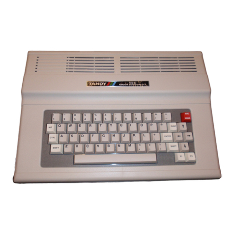
Figure 1-1 shows atypical
installation of the Color Computer 3.
The Color Computer 3contains an
internal BASIC program in ROM which
is accessed when the unit is powered
up. Other program modules/cartridges
may be inserted into the receptacle
on the right side of the unit. An
optional Multi-pak Interface module
allows up to four program paks to be
installed at the same time, with
selection of the specific module
active at any one time selected
either by software or by aswitch on
the Multi-pak Interface. Additional
peripheral devices, such as an
external disk drive, may be added to
the Color Computer 3for additional
memory storage and retrieval.
All input and output ports for the
Color Computer 3, with the exception
of the program module/cartridge slot
and the RGB monitor output (for
CM-8), are located on the rear panel
of the unit. These include the
joystick input ports (right and
left), Serial I/O, Cassette I/O, TV
output jack (for standard color
television set and composite
monitor), POWER ON/OFF switch and
RESET switch. Arecessed channel
switch (for selecting either channel
on the TV -3/4 for NTSC and 1/2 for
PAL version) is also located on the
rear panel of the unit.
1.2 System Description
The primary functions of the Color
Computer 3are performed by four
Large Scale Integration (LSI) chips,
plus Random Access Memory (RAM) and
Read Only Memory (ROM). These four
chips are labeled on the block
diagram as CPU, ACVC and two PIAs.
With only these four chips, plus
Random Access Memory (RAM), Read Only
Memory (ROM) and apower supply, the
Color Computer 3will operate and
provide video output (RF, Composite,
Analog RGB). However, to allow
communication with the outside world,
I/O interfaces must be added.
The main component of any computer
system is the Central Processing Unit
(CPU, IC1). It is the function of the
CPU to provide or request data and
select the proper address for this
data. In addition, the CPU is capable
of performing alimited set of
mathematical and logical operations
on the data.
ROM (IC2) has the function of
providing the CPU with apredefined
set of instructions. Without ROM, the
CPU would run wild and randomly
execute instructions. In normal
operation, the CPU jumps to the start
address in ROM, after the reset
switch has been pressed, and then
performs the reset program to set up
all of the programmable devices.
Following this, the BASIC interpreter
residing in ROM is in control of the
CPU.
Note: Before installing any
peripheral device, always remember to
unplug the Color Computer's power
cord. This will prevent damage to the
device or to the Color Computer 3.
-5-


