manuals.online logo
Brands
  1. Home
  2. •
  3. Brands
  4. •
  5. Tansun Quartzheat
  6. •
  7. Heater
  8. •
  9. Tansun Quartzheat Rio Grande RIO 315 EU User manual

Tansun Quartzheat Rio Grande RIO 315 EU User manual

©Tansun Limited 2008 Part No. 042223 Issue. 1
F o l l o w i n g i n f o r m a t i o n i s o n l y f o r E U - m e m b e r
s t a t e s :
The use of this symbol indicates that this roduct may not be treated as household waste.
By ensuring this roduct is dis osed of correctly, you will hel revent otential negative
consequences for the environment and human health, which could otherwise be caused by
ina ro riate waste handling of this roduct. For more detailed information about recycling
of this roduct, lease contact your local council, your household waste dis osal service or
the sho where you urchased the roduct.
Reference Manual
Rio Grande
UK & EUROPEAN MODEL HEATERS:
RIO 310 UK & RIO 310 EU,
RIO 315 UK & RIO 315 EU,
RIO 320 UK & RIO 320 EU.
S ectrum House, Unit 1, Ridgacre Road, West Bromwich,
West Midlands, B71 1BW, England.
Tel: +44 (0)121 580 6200 - Fax: +44 (0)121 580 6222
Email: [email protected] - Website: www.tansun.com
UK & EUROPEAN MODEL HEATERS WITH LIGHTS:
RIO 310LL UK & RIO 310LL EU,
RIO 315LL UK & RIO 315LL EU,
RIO 320LL UK & RIO 320LL EU.
R i s k o f F i r e
Kee combustible materials such as furniture, a ers, clothes and curtains at least 1.8m (6 feet) from the front of
the heater and away from the sides and rear. If the lam is to be used outside, we recommend that a water roof or
indoor socket is used.
2
I n t r o d u c t i o n
The Rio Grande heater roduces radiant heat like the sun, warming eo le and objects rather than the air in between. It is
mounted on an adjustable bracket that allows the heat to be directed exactly where it is required. Its attractive, lightweight de-
sign means that it is effective yet unobtrusive. The Rio Grande is designed for indoor and outdoor use so is therefore weather-
roof.
Please read the following instructions carefully before use. he safety of this heater is guaranteed only by its correct
usage in accordance with these instructions, therefore it is recommended that they are retained for future reference.
S p e c i f i c a t i o n
a b l e 1 . U K a n d E u r o p e a n H e a t e r s
Use MCB Ty e 3.
C a u t i o n
Before using this a liance:

Check that the voltage indicated on the ty e late corres onds to the mains su ly voltage.

Do not locate the heater immediately below a socket outlet.

Ensure that the heater has been securely fastened in its final mounting osition.

Remove the lug from the mains socket (or disconnect ole switch) during installation, cleaning and/or re-
lacing the emitter and always ensure that the emitter is cool.

Do not handle the halogen emitter with bare hands. If it is inadvertently touched, remove finger marks with a
soft cloth and methylated s irit or alcohol. Otherwise, the marks will burn into the quartz emitter causing
remature heater failure.

Do not use an extension cable with this roduct.

Kee the mains cable away from the body of the heater which will get hot during use.

Do not cover or obstruct the heater while it is in use.

The heater is not intended for use by young children or infirm ersons unless they have been adequately
su ervised by a res onsible erson to ensure that they can use the heater safely.

Do not insert any object through any slot or o ening in the heater.

Do not use if guard is not resent.

Do not install less than the minimum mounting distance from the floor.

Warning - this appliance must be earthed!
Model Voltage otal Current Min. height Min. dist. Min. dist. Dimensions Weight Ingress
(V) Power (A) from floor from ceiling from side WxHxD (kg) Protection
(W)
(m) (m) wall (m) (mm)
(IP)
Rio 310 230 1000 4.3 2.0 0.3 1.0 560 x 112 x 160 2.8 IP24
Rio 315 230 1500 6.5 2.0 0.3 1.0 560 x 112 x 160 2.8 IP24
Rio 320 230 2000 8.7 2.0 0.3 1.0 560 x 112 x 160 2.8 IP24
Model Voltage Heater Heater Lighting Lighting Min. height Min. dist. Min. dist. Dimensions Weight Ingress
(V) Power Current Power Current from floor from ceiling from side W x H x D (kg) Protection
(W) (A) (W) (A) (m) (m) wall (m) (mm)
Rio 310 230 1000 4.3 2 x 40 0.35 2.0 0.3 1.0 660 x 112 x 160 3.8 IP24
Rio 315 230 1500 6.5 2 x 40 0.35 2.0 0.3 1.0 660 x 112 x 160 3.8 IP24
Rio 320 230 2000 8.7 2 x 40 0.35 2.0 0.3 1.0 660 x 112 x 160 3.8 IP24
a b l e 2 . U K a n d E u r o p e a n H e a t e r s w i t h L i g h t s
Use MCB Ty e 3.
7
BLANK PAGE
6
3. Unscrew the four screws (see Fig. 1) from the end ca and remove from the heater body. Re eat at o osite end if re lacing both light
bulbs.
Fig. 1
4. Slide out the side cover(s) to reveal the bulb(s) as shown in Fig. 2.
5. Remove the light bulb by rotating it anti-clockwise until it is released from the bulb holder (Fig. 3).
Fig. 2
Fig. 3
6. Refit the new bulb(s) in reverse order ensuring they are not loose and all screws are fully tightened.
I n s t a l l a t i o n
The Rio Grande heater is fitted with 5 meters of su ly cable and a moulded lug, therefore it is
unnecessary to o en the terminal box in order to carry out normal installation of this roduct and should
not be interfered with.

We recommend using a RCD where a licable.

Please observe the minimum safe distance between the heater body and any inflammable surfaces.

If the su ly cord becomes damaged, it must be re laced by the manufacturer, its service agent or a
similar qualified erson in order to avoid a hazard.

When the electrical connection is outside, it is recommended that a water roof socket is used for the
connection. Otherwise, the lug should be connected to a socket indoors.

If in any doubt, lease contact a suitably qualified electrician.
M o u n t i n g

The Rio Grande heater can be mounted in a horizontal or vertical manner as the emitter is a universal
burning ty e. The Rio Grande heater with lights should only be mounted horizontally.

When mounting the Rio Grande heater and heater with lights in a horizontal manner, do not osition
the heater at an angle more than 90° and less than 30° as shown in Fig. A.

When vertically mounting the Rio Grande heater, ensure to leave a ga between the heater and
mounting surface (See Fig. C - dim A). The heater should always be angled downwards when
mounting this way with the terminal box at the bottom of the heater - see Fig. 4. Do not osition the
heater at an angle more than 45° and less than 30° to the horizontal as shown.

Always allow the heater to cool before attem ting to re osition/move. Never attem t to move the
heater while it is switched on!

Observe the minimum safe distance between the heater body and inflammable surfaces and objects
when mounting.

Please refer to Table 1 or 2 for the recommended ositioning of the heater.

Kee out of the reach of children.
1. Securely fasten the Rio Grande bracket to the mounting surface using the fixing holes in the
bracket. Please refer to Table 1 or 2 for recommended ositioning of the heater.
2. Fix in the required angular osition by tightening the fixing bolt on the bracket at the rear of the
heater.
3. Secure the su ly cable local to the Rio Grande using a ‘P’ cli (su lied) so the cable is
directed away from the heater and is not resting on the body or obstructing the air-vents.
Always isolate the heater from the mains supply when adjusting the angular position.
3
M a i n t e n a n c e
In the event of heater failure, or for spare parts or advice, please contact the manufacturer in the first instance.

Disconnect from the mains before commencing any maintenance rocedure including cleaning.

To ensure o timum heat effectiveness, it is recommended that that the guard and lemitter are removed and the reflector is wi ed with a lint-free
cloth before reassembling should the reflector show considerable signs of dust or dirt.
Y o u r R e p l a c e m e n t E m i t t e r
It is very im ortant that your re lacement emitter is exactly the same as the one it was su lied with. Failure to fit the exact same ty e could
cause the heater to fail or even become dangerous es ecially when used in an outdoor environment.
Please contact Tansun Limited to urchase your re lacement lam and state the model number of the heater you wish to fit the lam to.
4
4. Disconnect the lam from the connector blocks by unscrewing the screws highlighted above in Fig. 2.
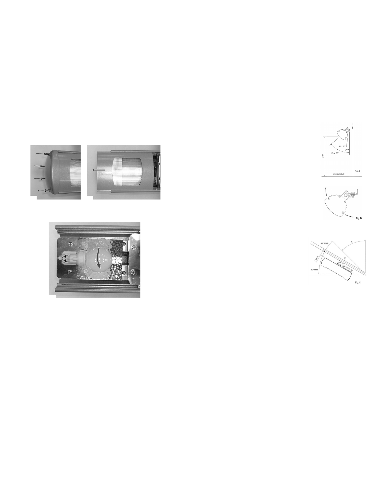
5. Unscrew the four screws (see Fig. 3) from the end ca and remove from the heater body. Re eat at o osite end.
R e p l a c i n g t h e E m i t t e r
If you are in any doubt about following the procedure below, please contact us for technical assistance. he mains power should
be disconnected before any attempts are made to replace the lamp. he following should be carried out with compliance to
latest IEE regulations. Please read the notes on the previous page with regards to handling and buying a replacement emitter
before proceeding.
1. Ensure the heater, emitter and on models with lights the bulbs are cool and the ower su ly is disconnected by removing the lug(s)
from the socket outlet.
2. Providing there is reasonable access and you are standing on a safe and stable latform, the emitter can be re laced with the heater
still mounted. Otherwise, remove the heater from its mounting and work on a safe, flat surface.
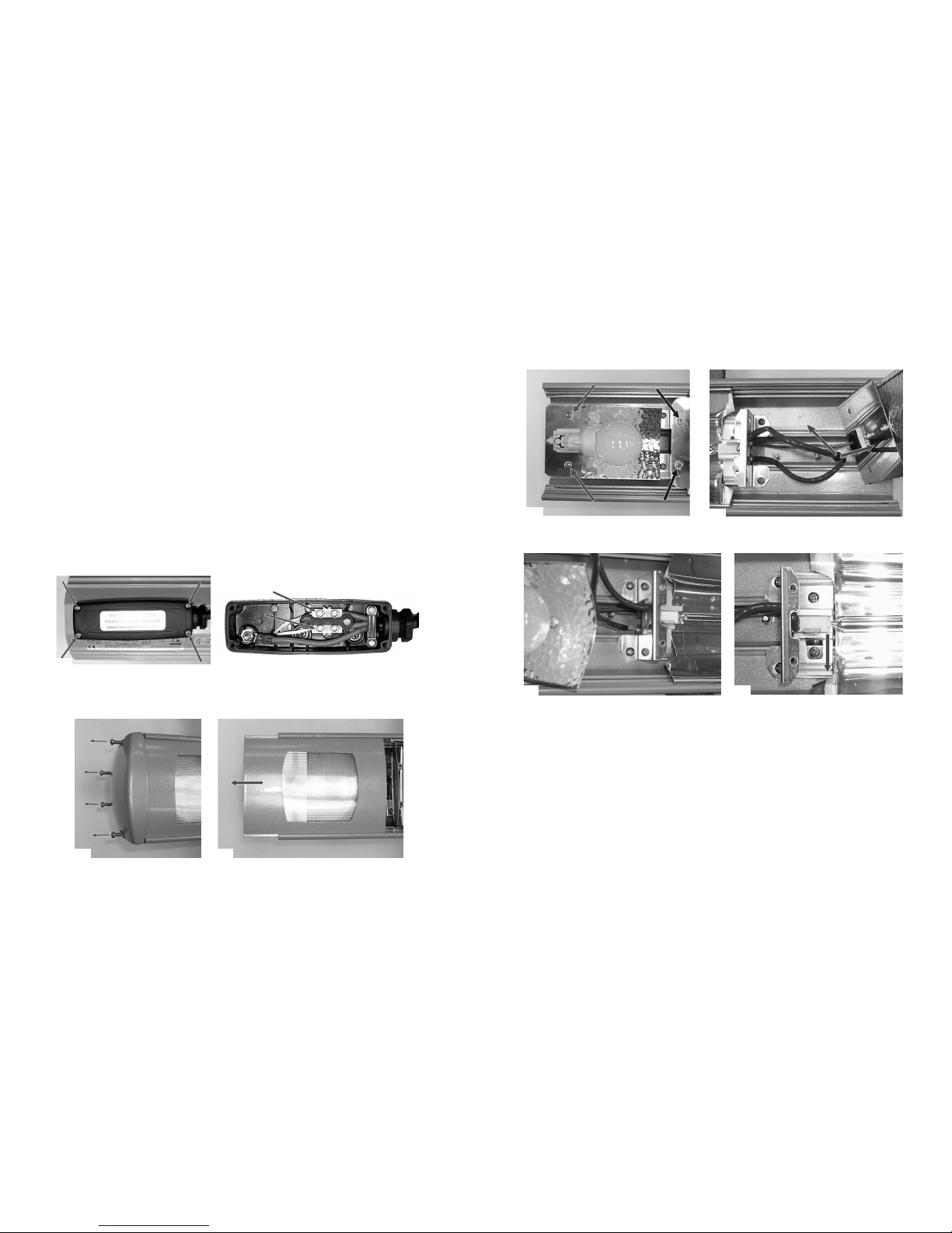
3. Remove the screws from the terminal box (Fig. 1) and lift off the cover.
Fig. 3 Fig. 4
6. Slide out the side covers from both ends and slide out the guard from either end (Fig. 3 & 4 shows side covers with lenses for models
with lights).
Y o u r R e p l a c e m e n t L i g h t B u l b s ( H e a t e r w i t h L i g h t s O n l y )
It is very im ortant that your re lacement light bulbs are exactly the same as the ones it was su lied with. These bulbs have been
designed to withstand high tem eratures so failure to fit the exact same ty e could cause the unit to fail or even become dangerous.
Please contact Tansun Limited to urchase your re lacement light bulbs and state the model number of the heater you wish to fit the light
bulbs to.
Fig. 1
Fig. 2
H a n d l i n g t h e R e p l a c e m e n t E m i t t e r
Your new emitter should not be handled with bare hands.
Remove finger marks with a soft cloth and methylated s irits or alcohol. Finger marks will burn into quartz causing remature lam failure.
5
7. Firstly remove the two screws as highlighted on the right of Fig. 5 to remove the side reflector. If your heater is a model with lights models
you should then remove the two screws holding the bulb late as highlighted on the left of Fig. 5 to allow the bulb late to be lifted. Re eat at
o osite end.
Fig. 5
8. Starting at the end where the emitter wires are fed through the gasket into the terminal box, if the heater has lights hold the bulb late out
of the way (Fig. 6) or if it is a heater only the wires will be clearly visible, gently ull the lam wires through the body of the heater so the
wires exit the terminal box (Fig 6).
Fig. 6
9. At the o osite end of the heater, if the heater has lights hold the bulb late out of the way (Fig. 7) or if it is a heater only the wire will be
clearly visible in the feeder tube, gently ull the lam wire out of the tube.
10. Pull the emitter wires through the side reflector bracket and then one at a time ull the s ring cli s back and lift u the ceramic ca s of
the emitter to remove it from the heater.
11. The emitter should now be removed from the heater. Refit the new emitter in reverse order ensuring the ceramic ca s are correctly
seated in the lam holders, no wires are tra ed and all screws are fully tightened.
Fig. 7 Fig. 8
R e p l a c i n g t h e L i g h t B u l b s ( H e a t e r w i t h L i g h t s O n l y )
If you are in any doubt about following the procedure below, please contact us for technical assistance. he mains power should
be disconnected before any attempts are made to replace the lamp. he following should be carried out with compliance to
latest IEE regulations. Please read the notes on the previous page with regards to handling and buying replacement bulbs before
proceeding.
1. Ensure the heater, emitter and light bulbs are cool and the ower su ly is disconnected by removing the lugs from the socket outlet.
2. Providing there is reasonable access and you are standing on a safe and stable latform, the light bulbs can be re laced with the heater
still mounted. Otherwise, remove the heater from its mounting and work on a safe, flat surface.
Continued...

This manual suits for next models

11

Other Tansun Quartzheat Heater manuals

Tansun Quartzheat Rio 010 User manual

Tansun Quartzheat

Tansun Quartzheat Rio 010 User manual

Tansun Quartzheat Spotter User manual

Tansun Quartzheat

Tansun Quartzheat Spotter User manual

Tansun Quartzheat SOR 210IP User manual

Tansun Quartzheat

Tansun Quartzheat SOR 210IP User manual

Tansun Quartzheat SORRENTO IP SINGLE SOR 210IP User manual

Tansun Quartzheat

Tansun Quartzheat SORRENTO IP SINGLE SOR 210IP User manual

Tansun Quartzheat RIO 210IP EU User manual

Tansun Quartzheat

Tansun Quartzheat RIO 210IP EU User manual

Tansun Quartzheat RIV ELITE 060 User manual

Tansun Quartzheat

Tansun Quartzheat RIV ELITE 060 User manual

Tansun Quartzheat Carnival CARN4 1X750H User manual

Tansun Quartzheat

Tansun Quartzheat Carnival CARN4 1X750H User manual

Popular Heater manuals by other brands

STIEBEL ELTRON CFK 5 Operation and installation

STIEBEL ELTRON

STIEBEL ELTRON CFK 5 Operation and installation

Mars LPV2 Series Installation, operation and maintenance manual

Mars

Mars LPV2 Series Installation, operation and maintenance manual

Jata JCTC3230 Instructions of use

Jata

Jata JCTC3230 Instructions of use

PVG Heator SRE 804 TC operating manual

PVG

PVG Heator SRE 804 TC operating manual

hairway YM-8006 user manual

hairway

hairway YM-8006 user manual

Sawo SAVONIA manual

Sawo

Sawo SAVONIA manual

THERMOWATT Smart Immersion Heater Installation and operating instructions

THERMOWATT

THERMOWATT Smart Immersion Heater Installation and operating instructions

BRAYER BR4803 instruction manual

BRAYER

BRAYER BR4803 instruction manual

MILL IB250 Assembly and instruction manual

MILL

MILL IB250 Assembly and instruction manual

Jata JCRC2115 Instructions of use

Jata

Jata JCRC2115 Instructions of use

Frico ELIRC manual

Frico

Frico ELIRC manual

Bimar S107.EU Instruction booklet

Bimar

Bimar S107.EU Instruction booklet

HOMCOM 820-310V00 user manual

HOMCOM

HOMCOM 820-310V00 user manual

EUROM Entourage 1500 instruction manual

EUROM

EUROM Entourage 1500 instruction manual

Coldair GCV440 operating instructions

Coldair

Coldair GCV440 operating instructions

Valor HORIZON 645CFV Clearview installation instructions

Valor

Valor HORIZON 645CFV Clearview installation instructions

Bimar DL06AB TURBO Instruction booklet

Bimar

Bimar DL06AB TURBO Instruction booklet

TradeQuip 1097T owner's manual

TradeQuip

TradeQuip 1097T owner's manual

manuals.online logo
manuals.online logoBrands
  • About & Mission
  • Contact us
  • Privacy Policy
  • Terms and Conditions

Copyright 2025 Manuals.Online. All Rights Reserved.