TapFlo DT Series Operation instructions

DT series
Active Pulsation Dampener
Original Instruction
edition 2020 rev 1
Read this instruction manual carefully,
before you install and operate the dampener.
Dampener models:
DT/ DTX 9/20/25/30
DT/ DTX 50/70/80
DT/ DTX 100/120/125
DT/ DTX 200/220/225
DT/ DTX 400/420/425
DT/ DTX 800/820/825

CONTENTS
IOM manual active pulsation dampeners 2
EC DECLARATION OF CONFORMITY 01/EC/DT/2016............................................................................. 4
EU DECLARATION OF CONFORMITY 01/ATEX/DT/2016........................................................................ 5
0. GENERAL......................................................................................................................................... 6
0.1. Introduction................................................................................................................................ 6
0.2. Warning symbols ....................................................................................................................... 6
0.3. Qualification and training of personnel................................................................................... 6
1. INSTALLATION ............................................................................................................................... 7
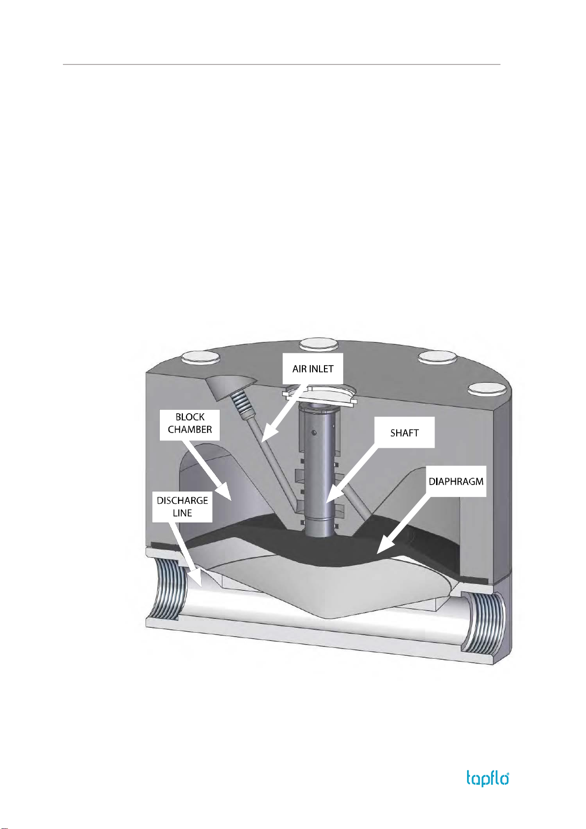
1.1. Operation principle.................................................................................................................... 7
1.2. Receiving inspection.................................................................................................................. 8
1.3. Storage........................................................................................................................................ 8
1.4. Health and safety ....................................................................................................................... 8
1.4.1. Protection ........................................................................................................................... 8
1.4.2. Explosion hazardous environments –ATEX..................................................................... 9
1.4.3. Air pressure......................................................................................................................... 9
1.4.4. Noise level .......................................................................................................................... 9
1.4.5. Temperature hazards....................................................................................................... 10
1.5. Air connection .......................................................................................................................... 10
1.6. Example of installation............................................................................................................ 11
1.6.1. Standard pump................................................................................................................. 11
1.6.2. TF pump ............................................................................................................................ 11
2. OPERATION .................................................................................................................................. 12
2.1. Before operating the dampener ............................................................................................. 12
2.2. Disposal after expiration of the expected lifetime ............................................................... 12
2.3. Actions in emergency .............................................................................................................. 12
2.4. Residual risks ............................................................................................................................ 12
3. MAINTENANCE ............................................................................................................................ 13
3.1. When the dampener is new or reassembled.......................................................................... 13
3.2. Routine inspection ................................................................................................................... 13
3.3. Complete inspection ................................................................................................................ 13
3.4. Location of faults ..................................................................................................................... 14
3.5. Disassembly of the dampener................................................................................................. 15
3.5.1. Before the disassembly procedure ................................................................................. 15
3.5.2. Disassembly procedure.................................................................................................... 15
3.6. Assembly of the dampener ..................................................................................................... 17
3.6.1. Test run ............................................................................................................................. 19

CONTENTS
IOM manual active pulsation dampeners 3
4. OPTIONS ....................................................................................................................................... 20
4.1. DTB series ............................................................................................................................. 20
4.2. DTF series.............................................................................................................................. 20
5. SPARE PARTS................................................................................................................................ 21
5.1. Spare parts drawing - PE & PTFE, Aluminium ....................................................................... 21
5.2. Spare parts list –PE & PTFE, Aluminium................................................................................ 21
5.3. Spare parts drawing –Stainless steel industrial and sanitary ............................................. 22
5.4. Spare parts list –steel and sanitary ........................................................................................ 22
5.5. Stocking recommendation...................................................................................................... 23
5.6. How to order parts................................................................................................................... 23
5.7. Dampener code ........................................................................................................................ 23
6. DATA ............................................................................................................................................. 24
6.1. Overall dimensions .................................................................................................................. 24
6.1.1. Dimensions table –Plastic (PE&PTFE)............................................................................ 25
6.1.2. Dimensions table –Metal series (aluminium) ............................................................... 26
6.1.3. Dimensions table –Metal series (Stainless Steel).......................................................... 28
6.1.4. Dimensions table –Sanitary series ................................................................................. 29
6.2. Tightening torques .................................................................................................................. 30
6.3. Technical data .......................................................................................................................... 30
7. WARRANTY .................................................................................................................................. 32
7.1. Warranty form.......................................................................................................................... 32
7.2. Returning parts ........................................................................................................................ 33
7.3. Warranty ................................................................................................................................... 33

EC DECLARATION OF CONFORMITY 01/EC/DT/2016
Series:
DT(…)
Serial numbers:
2018 - … (from 1801-…)
Manufactured by:
Tapflo AB
Filaregatan 4
442 34 Kungälv, Sweden
This declaration of conformity is issued under the sole responsibility of the manufacturer.
Object of declaration: ACTIVE PULSATION DAMPENERS
The object of the declaration described above is in conformity with the relevant Union
harmonisation legislation:
•Directive 2006/42/EC of European Parliament and of the Council of 17 May 2006 on machinery,
amending Directive 95/16/EC;
Mr Michał Śmigiel is authorized to compile the technical file.
Tapflo Sp. z o.o.
ul. Czatkowska 4b
83-110 Tczew
Signed for and on behalf of
Tapflo AB
Håkan Ekstrand
Managing Director
Tapflo AB, 01.01.2018r

EU DECLARATION OF CONFORMITY 01/ATEX/DT/2016
Series:
DTX(…)
Serial numbers:
2018 - … (from 1801-…)
Dampener materials:
Conductive PE, Conductive PTFE, Conductive PP, Aluminium, Stainless steel AISI 316/316L
Manufactured by:
Tapflo AB
Filaregatan 4
442 34 Kungälv, Sweden
This declaration of conformity is issued under the sole responsibility of the manufacturer.
Object of declaration: CONDUCTIVE PULSATION DAMPENERS
The object of the declaration described above is in conformity with the relevant Union
harmonisation legislation:
•Directive 2006/42/EC of European Parliament and of the Council of 17 May 2006 on machinery
•Directive 2014/34/EU of the European parliament and of the council of 26 February 2014 on
Equipment or Protective System intended for use in potentially explosive atmospheres
and is intended for operation in potentially explosive atmospheres according to:
Equipment group: IIG (Gas) / IID (Dust)
Category: 2
Apparatus group: IIB
Temperature class: T4
Signed for and on behalf of Tapflo AB
Håkan Ekstrand
Managing Director
Tapflo AB, 16.04.2016r

0. GENERAL
IOM manual active pulsation dampeners 6
0. GENERAL
0.1. Introduction
The active pulsation dampener is the most efficient way to remove pressure variations on the
discharge of the pump. The Tapflo pulsation dampener works actively with compressed air and
a diaphragm, automatically setting the correct pressure to minimize the pulsations. The
pulsation dampener is available for all Tapflo pump sizes and material versions.
With proper attention to maintenance, Tapflo active pulsation dampeners will give efficient and
trouble free operation. This instruction manual will familiarize operators with detailed
information about installing, operating and maintaining the dampener.
0.2. Warning symbols
The following warning symbols are present in this instruction manual. This is what they say:
This symbol stands next to all safety instructions in this instruction manual where
danger to life and limb may occur. Observe these instructions and proceed with
utmost caution in these situations. Inform also other users of all safety instructions.
In addition to the instructions in this instruction manual, the general safety and
accident prevention regulations must be observed.
This signal stands at points in this instruction manual of particular importance for
compliance with regulations and directives, for correct work flow and for the
prevention of damage to and destruction of the complete dampener or its
subassemblies.
0.3. Qualification and training of personnel
The personnel in charge of installation, operation and maintenance of the dampener we produce
must be qualified to carry out the operations described in this manual. Tapflo shall not be held
responsible for the training level of personnel and for the fact that they are not fully aware of
the contents of this manual.
In case any instructions in this manual are unclear or any information is lacking, please contact
Tapflo before handling the dampener.

1. INSTALLATION
IOM manual active pulsation dampeners 7
1. INSTALLATION
1.1. Operation principle
The pulsation dampener’s main function is to remove pressure variations on the discharge of
the pump. The dampener works actively with compressed air and a diaphragm, automatically
setting the correct pressure to minimise the pulsations.
The air pressure supplied to the dampener is the same as the one supplied to the pump. The
medium flowing through the dampener affects the diaphragm, which by means of the
compressed air on the air side compensates the fluctuations of pressure in the discharge line.
The air concentrated in the dampeners block works as a spring for the medium flowing through
the dampener.
When operating, dampener does not consume compressed air. It is only consumed during
setting phase, when pump duty point is being changed.

1. INSTALLATION
IOM manual active pulsation dampeners 8
1.2. Receiving inspection
Although precaution is taken by us when packing and shipping, we urge you to carefully check
the shipment on receipt. Make sure that all parts and accessories listed on the packing list are
accounted for. Immediately report any damage or shortage to the transport company and to
us.
-Before handling the dampener check the weight of the dampener (see 6.3. “Technical
data”). Refer to Your local standards on how to handle the dampener. If the weight is
excessive to transport by hand it must be lifted using slings and a suitable lifting device
e.g. a crane or forklift.
-Always use at least two slings and make sure they are secured in such a way to prevent
the dampener from slipping and that the dampener is hanging straight. Never lift the
dampener with only one sling. Incorrect lifting can cause serious injury and/or damage to
the dampener.
-Never lift the dampener under pressure.
-Be careful that nobody passes under the dampener when lifted.
-Never try to lift the dampener by the connections (e.g. flange pipes) or hoses attached to
the dampener.
-As an option, dampener can be equipped with lifting eyebolts connected with the
dampener pin screws.
1.3. Storage
If the equipment is to be stored prior to installation, place it in a clean location. The dampener
should be stored in an ambient temperature of 15°C (59°F) to 25°C (77°F) and relative humidity
below 65%. It should not be exposed to any heat source e.g. radiator, sun as this could result in
a negative way on the tightness of the dampener. Do not remove protective covers from the
inlet/outlet and air connections which have been fastened to keep dampener internals free of
debris. Clean the dampener thoroughly before installation.
1.4. Health and safety
The pulsation dampener must be installed according to local and national safety rules.
The dampeners are constructed for particular applications. Do not use the dampeners on
applications different from that for which it was sold without consulting us to ascertain
its suitability.
The dampeners are tested with water. If the pumped product can come into reaction with
water, please make sure the device is dry before putting it into operation.
1.4.1. Protection
In the interest of health and safety it is essential to wear protective clothing and safety goggles
when operating, and/or working in the vicinity of Tapflo dampeners.

1. INSTALLATION
IOM manual active pulsation dampeners 9
1.4.2. Explosion hazardous environments –ATEX
The standard DT series dampeners are not allowed to operate in environments where there is
danger of explosion. Static electricity may occur in the dampener under operation, which may
cause explosion and injury. Special conductive DTX dampeners are available for such
applications. Follow below instructions and local/national rules for safe use.
ATEX (directive 2014/34/EU) classification of Tapflo DTX dampeners.
ATEX II 2 GD IIB cT4
Equipment group: II –all other explosive areas than mines;
Category group: 2–high level of protection (can be used in zone 1);
Atmosphere: G–gas;
D –dust;
Explosion group: IIB –such as ethylene;
Type of protection: c–constructional safety;
Temperature class: T4 –in the event of a malfunction, the maximum temperature of a
surface that may be exposed to gas T4 = 135 °C.
Earth connection of the dampener and other equipment
Connect a suitable earth wire to the stainless steel earth connection that is placed on the top
or on the side of the dampener block , depending on dampener size and execution. Connect
the other end of the earth wire to earth and also make sure that other equipment like
hoses/pipes/containers etc. are properly earthed/connected.
1.4.3. Air pressure
The maximum air pressure for standard Tapflo dampeners is 8 bar. Higher air pressure than 8
bar can damage the dampener and may cause injury to personnel in vicinity of the dampener.
For higher pressure rate, up to 16 bar (depending on the size) see optional dampener execution
in chapter 4.2. DTF series.
Please make sure that supply air to the dampener must have the same flow and pressure as the
pump that dampener is installed with.
1.4.4. Noise level
At tests, the noise level from a Tapflo dampener has not exceeded 70 dB(A). Under some
circumstances, for example if the dampener is operating under high air pressure at low
discharge head, the noise can be inconvenient or hazardous for personnel staying for long
periods in the vicinity of the dampener. This hazard can be prevented by:
➢using suitable ear protection;
➢lowering the air pressure and/or raising the discharge head.

1. INSTALLATION
IOM manual active pulsation dampeners 10
1.4.5. Temperature hazards
➢Raised temperature can cause damage on the dampener and/or piping and may also be
hazardous for personnel in the vicinity of the dampener/piping. Avoid quick temperature
changes and do not exceed the maximum temperature specified when the dampener was
ordered. See also general max temperatures based on water in chapter 6.3. “Technical
data”
➢When the dampener is exposed to ambient temperature variations or if there is big
difference between the temperature of the product and the surrounding, the tightening
torques of the housing nuts should be checked periodically as part of preventive
maintenance.
➢If a hot product is pumped, the dampener should not stand still when filled for a longer
period of time. This could cause leakage.
➢Below 0°C (32°F) plastic materials become more fragile what can cause increased wear of
parts made of these materials. This is a hazard that has to be accepted when pumping cold
products. Also in such case, when a dampener is not operation it should be drained of all
liquid.
➢The fluid remaining in the connected piping, as well as in the dampener itself, may expand
because of freezing or heat, which may cause damage to the dampener or/and piping,
and lead to leakage of the fluid.
1.5. Air connection
Screw the air hose into the air intake on the centre block of the dampener with for example a
quick release coupling. For best efficiency, use the same hose diameter as the internal diameter
of the connection on the air intake.

1. INSTALLATION
IOM manual active pulsation dampeners 11
1.6. Example of installation
1.6.1. Standard pump
1.6.2. TF pump
The pulsation dampener must be installed according to the sketch. It can be connected with a
nipple immediately after the pump outlet, or placed independent of the pump with a flexible
hose between the pump and the dampener. Makes sure that the dampener does not cause any
tension or strain to the pump. The air hose must be connected to the pump air hose with a T-
connection, between the pump and filter-regulator (See sketch).
ATTENTION! The T-connection must be installed after the filter-regulator but before the
needle valve. It is also mandatory that the air to the dampener has the same flow and pressure
as the pump!
In order to ensure the most effective pulsation dampening the dampener should be installed
not further than five times the diameter of the pipeline from the discharge flange of the pump
L<5*Ø
NOTE!
It is recommended to install a check / shut off valve after the dampener. If the pump and
dampener are placed in a system with other pumps or in a pressurized system it is essential to
cut the dampener form the installation and relief the pressure from the piping. In the case where
the dampener is not cut off, the diaphragm is permanently under pressure from the liquid side
without any support from the air side thus leaving it unbalanced resulting in premature damage
of the diaphragm.

2. OPERATION
IOM manual active pulsation dampeners 12
2. OPERATION
2.1. Before operating the dampener
➢Make sure the dampener is installed according to the installation instruction.
➢When installation is new or the dampener is reinstalled, a test run with water must be
conducted to make sure that the dampener operates normally and does not leak.
➢When installation is new or the dampener reinstalled, check the dampener housing
nuts tightening torque (see chapter 6.2 “Tightening torques”). After approximately one
week of operation, the torque must be checked again. This is important to prevent
possible leakage.
2.2. Disposal after expiration of the expected lifetime
The metallic components like aluminium, stainless steel and carbon steel can be recycled.
Plastic parts are not recyclable and must be disposed of as residual waste. The dampener
must be disposed of properly, according to local regulations. It should be noted that
potentially dangerous fluid residues may remain in the dampener and can create a hazard
to the operator or the environment, therefore the dampener has to be thoroughly cleaned
before disposal.
2.3. Actions in emergency
In case of transferred liquid leakage, the air supply have to be closed and the pressure
released. During spillage of an aggressive liquid, local and national safety rules must be
followed.
2.4. Residual risks
Even with proper application and observance of all points listed in this operating manual,
there is still an estimable and unexpected residual risk when using the pumps. It may leak,
fail due to wear, application-related causes or system-related circumstances.

3. MAINTENANCE
IOM manual active pulsation dampeners 13
3. MAINTENANCE
3.1. When the dampener is new or reassembled
If the dampener is new or reassembled after maintenance it is important to retighten
the dampener housing nuts (pos. 37) after a week of operation.
Make sure to use the right torque –see chapter 6.2. “Tightening torques”.
3.2. Routine inspection
Frequent observation of the dampener operation is recommended to detect problems. For
possible issues see chapter 3.4. "Location of faults".
Leaking liquid from the dampener and changes of performance may also be detected.
We recommend to conduct a daily check and keep records of the following:
➢Leakage of fluid from any connection of the dampener
➢Tightness of all connection parts of the dampener
In case any of the above is not fulfilled, do not start the device and implement corrective
actions. Establish a preventive maintenance schedule based on the device service history.
Scheduled maintenance is especially important to prevent spills or leakage due to
diaphragm failure. Although dampener applications vary, a general guideline is to re-torque
the nuts every two weeks.
3.3. Complete inspection
The intervals for a complete inspection depend upon the operation conditions of the
dampener. The characteristics of the liquid, temperature, materials used in the dampener
and running time decide how often a complete inspection is necessary.
If a problem has occurred, or if the dampener is in need of a complete inspection, refer to
chapters 3.4 "Location of faults" and 3.5 "Disassembly of the dampener". You are of course
warmly welcome to consult us for further help.
Parts that are subject to wear should be kept in stock, see our recommendations in chapter
5.5. “Stocking recommendation”.

3. MAINTENANCE
IOM manual active pulsation dampeners 14
3.4. Location of faults
PROBLEM
POSSIBLE FAULT
POSSIBLE SOLUTION
The dampener does not
work
The air pressure is to low
Check if set pressure equals set pressure for the
pump
The air connection is blocked
Check / clean air supply connection
Muffler is blocked
Check / clean / replace muffler
Dirt in the dampener chamber
Remove debris from the chambers
Diaphragm breakdown
Replace diaphragm
Liquid leaks from the
dampener
Screws on the housing not properly
tightened
Check tightening torques of the screws
Damaged diaphragm
Check / replace diaphragms
Tension / stress form the installation
Adjust installation, eliminate stress, provide
separate support for dampener
Liquid comes out of the
muffler
Diaphragm breakdown
Replace diaphragm
Continuous air leakage
through muffler
Air leakage through diaphragm shaft
Replace dampener block seal or/and diaphragm
shaft
Diaphragm breakdown
Wrong selection of material
Contact us for information on material selection
Too high pressure in the installation
Use pressure regulator for protection
Too high pressure on suction side
Make sure there is pressure balance between the
air and liquid side of the diaphragm

3. MAINTENANCE
IOM manual active pulsation dampeners 15
3.5. Disassembly of the dampener
The numbers put in brackets, refer to the part numbers in the spare part drawings and spare
part lists in chapter 5 “Spare parts”.
3.5.1. Before the disassembly procedure
Be sure to drain all liquid from the dampener. Cleanse or neutralize the thoroughly.
Disconnect the air supply and then the inlet and outlet.
3.5.2. Disassembly procedure
Fig. 3.5.1
By means of a screwdriver, remove the circlip [27]
and muffler [25]
Fig. 3.5.2
Remove the nut covers [579] from the dampener
housing and block
Fig. 3.5.3
Using two spanners unscrew the nuts [37] cross-
side and take them out alongside with the washers
[38].
Fig. 3.5.4
Take out the dampener block [12].

3. MAINTENANCE
IOM manual active pulsation dampeners 16
Fig. 3.5.5
Take the pin screws [14] out of the dampener
housing [11].
Fig 3.5.6
Unscrew the diaphragm [15] by hand (clockwise).
Fig 3.5.7
Using an Allen key, unscrew the shaft ending
[1652] from the diaphragm.
Fig 3.5.8
Push out the shaft [1651] from the dampener
housing
Fig 3.5.9
Check the inner seals [36] and O-rings [47]. If
necessary, take them out using a screwdriver.
NOTE! If these parts are removed, they must be
replaced with new ones. If the dampener sealing
is worn, also check the shat for wear and if
necessary replace it.
The dampener is now completely disassembled. Check all components for wear or damage
and replace if necessary.

3. MAINTENANCE
IOM manual active pulsation dampeners 17
3.6. Assembly of the dampener
The assembly procedure is done in the reverse order to the disassembly.
Nevertheless there are a few things that you have to remember in order to assemble the
dampener correctly.
Fig. 3.6.1
Using a screwdriver, insert the O-rings [47] into the
dampener block [12].
Fig. 3.6.2
Using a pair of pliers, insert the seals [36] into the
dampener block [12]. To make the procedure easier
bend the seals into a kidney shape and then fit them
with a screwdriver.
Fig. 3.6.3
Push the shaft [1651] into the dampener block [12].
Fig. 3.6.4
Screw the shaft ending [1652] into the diaphragm
[15].
NOTE It is very important to screw the shaft
ending(using an allen key) as deep as possible so it
won’t have the tendency to unscrew during operation
Fig. 3.6.5
Screw the diaphragm [15] with the shaft ending
[1652] onto the shaft [1651].
NOTE! When the diaphragm is screwed in the holes
in the diaphragm must be aligned with the holes in
the block.

3. MAINTENANCE
IOM manual active pulsation dampeners 18
Fig. 3.6.6
Push the diaphragm [15] in, so that it is touching the
dampener block [12].
Fig. 3.6.7
Put the pin screws [14] and washers [38] into the
dampener housing [11].
Fig. 3.6.8
Screw the nuts [37] onto the pin screws [14] so that
ca. two threads are visible over the nut.
Fig. 3.6.9
Turn over the dampener housing [11] and insert the
dampener block [12] onto the pin screws [14].
Fig. 3.6.10
Insert the washers [38] and nuts [37] on the pin screws
[14] from the side of the block and pre-tighten the
nuts cross side.
Fig. 3.6.11
Tighten the nuts [37] cross-side by means of a torque
wrench with the appropriate torque (see chapter 6.2.).

3. MAINTENANCE
IOM manual active pulsation dampeners 19
Fig. 3.6.12
Insert the nut covers [579] on both sides of the
dampener.
Fig. 3.6.13
Insert the muffler [25] and the circlip [27] in a circular
manner.
3.6.1. Test run
We recommend you to conduct a test of the dampener before installing it in the system, to
detect if there is no air leakage through diaphragm shaft. In order to do so, supply
pressurized air through air inlet. Proper operation is, when there is no continuous air flow
through the muffler.
Note! Due to its principle of operation, when supplied with pressurized air, shaft may
perform one stroke, resulting in short air release through muffler, which is not considered
as a leakage.
After one week of operation retighten the nuts with appropriate torque.

4. OPTIONS
IOM manual active pulsation dampeners 20
4. OPTIONS
4.1. DTB series
The DTB series equipped with fully pneumatic control system “Guardian” is perfect choice
when the diaphragm rupture has to be immediately detected in order to avoid product
leak to the environment. When rupture is detected the pump is automatically stopped
and an alarm can be generated. For detailed guidelines see „Guardian system” IOM
manual.
Available for sizes:
➢DTB20, 25, 30
➢DTB50, 70, 80
➢DTB100, 120, 125
➢DTB200, 220, 225
➢DTB400, 420, 425
4.2. DTF series
The DTF series pulsation dampeners are special execution used widely with the TF series AODD pumps.
Reinforcement steel plates are used to make the device more robust. Thanks to this, DTF dampeners
can work within higher operating pressures.
The maximum air supply pressure:
➢DTF50, DTF70, DTF100 and DTF120 –16 bar,
➢DTF220 and DTF420 –14 bar,
➢DTF200 and DTF400 –12 bar.
Keep in mind that TF pumps are supplied with air through the pressure booster. As a
result the air directed to the pump can be multiplied up to 2 times. For detailed
information see TF series IOM manual.
Other manuals for DT Series
1
This manual suits for next models
38
Table of contents
Other TapFlo Industrial Equipment manuals