TapFlo LBC Series User manual

IOM Manual – IBC Mixers
Mixers - LBC/HBC 3
IBC Mixers
Series – LBC, HBC
Edit. 2022
IOM manual
Read this instruction manual carefully,
before you install and operate the pump

IOM Manual – IBC Mixers
Mixers - LBC/HBC 2
1. General Instructions
1.1. Declaration of Conformity
1.2. Codification
1.3. Inspection
1.4. Storage
1.5. Description
1.6. Safety
2. Installation and Operation
2.1. Installation
2.2. Operation
2.3. Fault Diagnosis
3. Maintenance
3.1. Routine Maintenance
3.2. Lubrication
3.3. Tightening Torques
3.4. Air motor – Flushing
3.5. Material Disposal
3.6. Ordering Spare Parts
4. Supplementary Instructions and Drawings
4.1. Mixer Assembly Drawing
4.1.1. Mixer with Electric Drive
4.1.2. Mixer with Air Drive
4.2. Mixer Shaft – Direction of Rotation
4.3. Air Requirements
4.4. Impeller Installation
5. Warranty
5.1. Returning Parts
5.2. Warranty

IOM Manual – IBC Mixers
Mixers - LBC/HBC 3

IOM Manual – IBC Mixers
Mixers - LBC/HBC 4
1.2. Codification
LBC
-
075
E
-
4F
1
2
3
4
1. Product signature:
HBC – High-speed IBC Mixer (direct drive) – 1450rpm
LBC – Low-speed IBC Mixer – 236rpm
2. Nominal power
Signature
Nominal Power
037
0,37kW
075
0,75kW
150*
1,5kW
220*
2,2kW
*available only for LBC Mixers
3. Drive Type
A – Air motor with control valve for manual speed regulation
E – Electrical motor (1450rpm) for HBC, Gearmotor (~236rpm) for LBC
4. Special executions
1 – Type of impeller
Blank – Std. Impeller (Fixed impeller for HBC, folding impeller for LBC)
E– Std. Impeller + F-280 fixed impeller (280mm diameter)
F – Std. Impeller + F-300 fixed impeller (300mm diameter)
G– Std. Impeller + F-320 fixed impeller (320mm diameter)
H– Std. Impeller + F-360 fixed impeller (360mm diameter)
J– Std. Impeller + Low-level kicker with a longer shaft
2 – Material of wetted parts (impeller and shaft)
Blank – AISI316 stainless steel
P- Polypropylene
Y– AISI 316 stainless steel, PFA coated
Z– AISI 316 stainless steel, ECTFE coated
3 – Shaft Length
Blank – standard length
S– off-standard shaft length
4 – Electrical motor supply
Blank – 3-phase supply (400V at 50 Hz)
P– 1-phase supply (230V at 50 Hz)

IOM Manual – IBC Mixers
Mixers - LBC/HBC 5
5 – Frequency Inverter
Blank – none
D– Build on frequency inverter
E– External frequency inverter
6 – Optional frame connection
Blank – none
H– Hopper for powders
L– Liquid inlet
7 – Lifting arrangement
Blank – Standard lifting frame with eye bolt
F– Forklift module
8 – IBC tank dimensions
Blank – standard 1000 lt. IBC
S– off-standard execution of the IBC

IOM Manual – IBC Mixers
Mixers - LBC/HBC 5
1.3. Inspection
On receiving delivery of your IBC Mixer please inspect carefully to confirm that
your mixer has been received un-damaged and to the correct specification. Report any
shortages or damage immediately in writing to the carrier or supplier. Contact details
can be found at the back of this manual.
1.4. Storage
IBC Mixers series LBC, HBC should be stored in an indoor, clean, dry location
with a controlled temperature of 15°C to 40°C until the mixer is ready to be used.
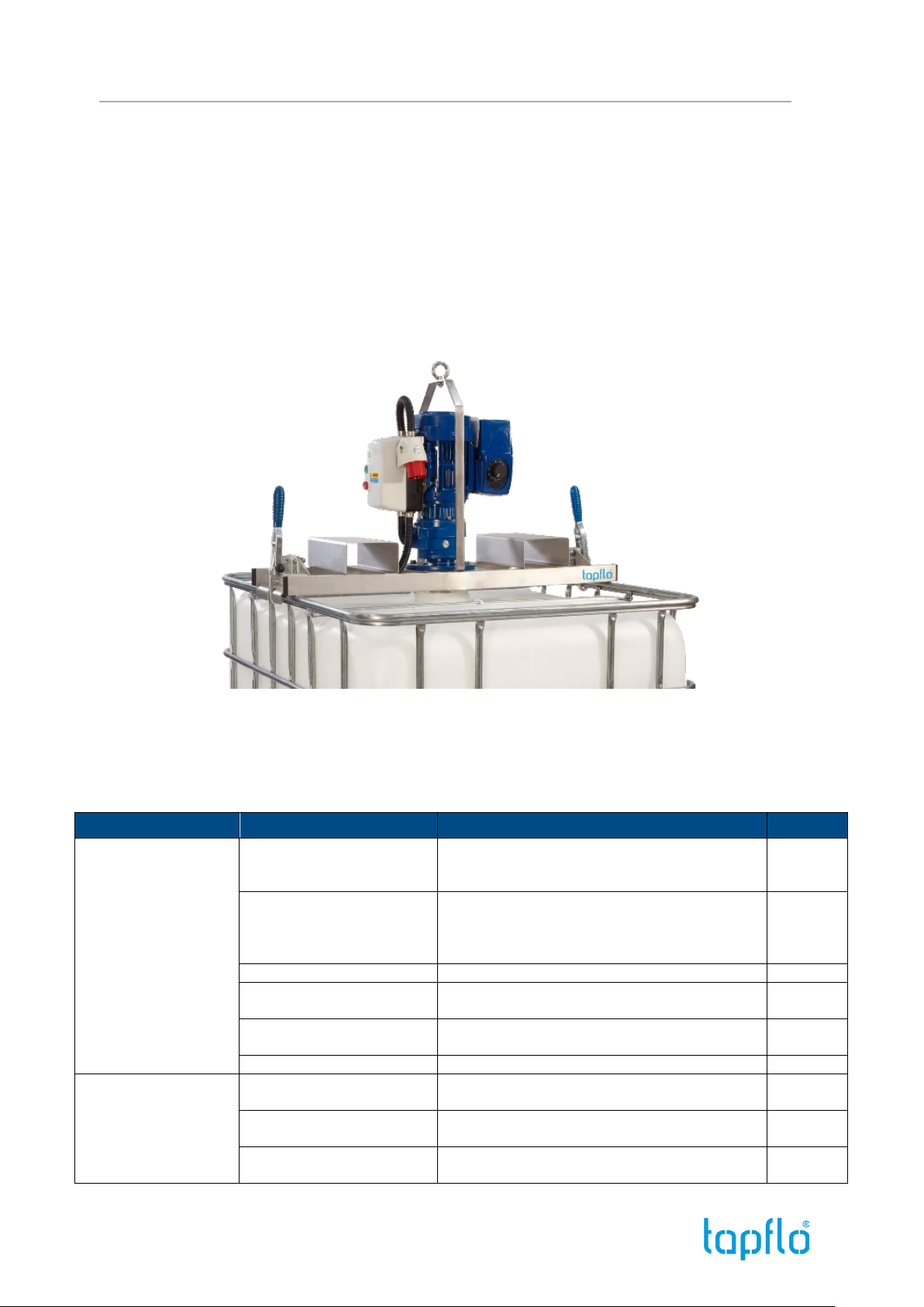
1.5. Description
Tapflo IBC Mixers series LBC, HBC are designed for use on Industry standard
Intermediate Bulk Containers (IBC) with a 150mm screw cap and are suitable for most
container types.
The IBC mixers are for use indoors in a safe area only and is fitted with a DOL
starter with overload protection and a safety switch to prevent the mixer operating if the
mixer is not securely mounted on an IBC and a 16 AMP appliance Inlet plug protection
IP44 - splash proof.
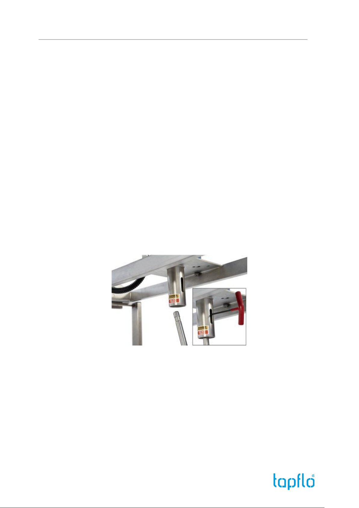
The mixer drive is supported on a lightweight stainless steel bridge which
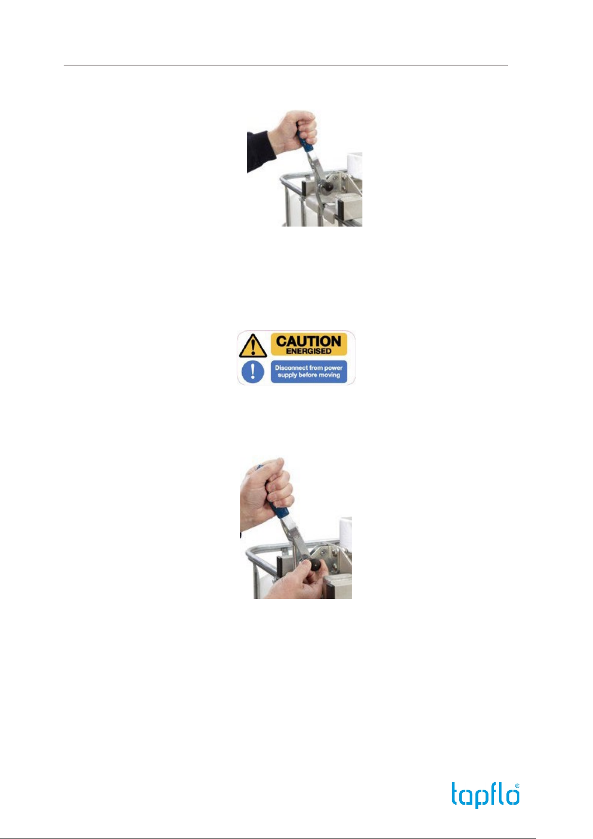
mounts directly onto the IBC and is held in place with quick action toggle clamps,
standard lifting is an eye bolt for lifting with a hoist or optional fork lift module.
1.6. Safety
The following instructions are important.
• Observe all site safety procedures installing and operating your IBC mixer
• Familiarize yourself with the material being mixed in the IBC and obtain product safety
data sheets, protective clothing and appropriate eye protection before proceeding.
• Use lifting equipment i.e. fork lift or hoist to install the mixer onto an IBC mixer. Mass
in Kg is indicated on the mixer nameplate.
• Mount the mixer securely onto the IBC complete with shaft and impeller before
connecting to the power supply.
• Disconnect from the power supply before moving the mixer or carrying out
maintenance.
• Do not touch any moving / rotating parts.
• Do not touch the motor after use - Hot Surface
WARNING – failure to observe safety instructions could cause severe personal injury.

IOM Manual – IBC Mixers
Mixers - LBC/HBC 7
2. Installation and Operation
2.1. Installation
The mixers with electric drive are supplied pre-wired and fitted with a DOL
starter, overload protection, safety interlock and appliance Inlet Plug.
The plug colour indicates the power supply required.
•Red - indicates a 400v 3ph 50 Hz supply
•Blue - indicates a 220-240v 1ph 50 Hz supply
•Yellow - indicates a 110v 1ph 50 Hz supply
The mixers with pneumatic drives are supplied with a flow control valve to regulate the
motor speed and an exhaust muffler.
1. Check that the motor / starter voltage requirements correspond with the supply
or verify if compressed air supply system is suitable in case of mixer with air
motor.
2. Check that the mixer shaft direction of rotation corresponds to the rotation
arrow placed on the mixer nameplate - rotation is clockwise when viewed from
above.
3. Changes to reverse the direction of rotation must be done by qualified personnel
only.
4. Fit the impeller on to the mixer shaft, dimple the shaft on assembly for the set
screws and tighten securely.
5. Fit the mixer shaft into the drive head coupling and tighten the 2 set screws
(Item 5) through the slot provided in the coupling guard.
6. Lower the mixer on to the IBC frame with a forklift truck or hoist using the eye
bolt provided on the mixer.

IOM Manual – IBC Mixers
Mixers - LBC/HBC 8
7. Securely fasten the mixer onto the IBC frame with the 2 quick action clamps
provided - adjust the clamps if necessary.
8. When the mixer is securely mounted on the IBC frame the power supply or
compressed air supply can be connected if safe to do so.
9. After use before moving the mixer - isolate from the power supply and
disconnect the lead to the appliance plug. In case of an air motor, it should be
disconnected from the compressed air supply.
10. Check that the securing clamps have been released before lifting / removing
the mixer from the IBC. The clamps are fitted with a locking plunger - pull the
button to release as illustrated.

IOM Manual – IBC Mixers
Mixers - LBC/HBC 9
2.2. Operation
Tapflo Mixers series LBC, HBC can be driven by an electric motor with a DOL
starter or gearmotor with a frequency inverter. Mixer shaft speed can be change by
turning the potentiometer on the inverter - for more detailed instruction please refer to
the Leroy Somer instruction manual supplied with this mixer. Mixers can be also driven
by an air motor equipped with exhaust muffler and a flow control valve to regulate the
motor speed.
Always ensure access to the power supply or compressed air supply is kept clear.
Before operation visually check that all components are in a serviceable condition and
not damaged.
The mixer can be operated at any liquid level.
2.3. Fault Diagnosis
Fault
Possible cause
Action
Drive
Mixer motor runs but
not mixing the IBC
contents very well
Impeller rotating in the wrong
direction
Check that the direction of rotation corresponds with the
arrow on the mixer nameplate.
Rotation is clockwise when viewed from above.
All drives
Impeller rotating in the wrong
direction
Check that the direction of rotation corresponds with the
arrow on the mixer nameplate & that the flow control
and muffler are on the correct ports.
Rotation is clockwise when viewed from above.
Air drives
Shaft loose in the drive coupling
Check shaft retaining grub screw are tight.
All drives
Folding impeller not opening
Check that the impeller is installed so the blades hang
downwards when not operating.
All drives
Product different - higher SG or
viscous product being mixed.
Contact Tapflo or your local distributor for advice.
All drives
Speed set is too low
Increase speed at VFD panel.
VFD drive
Motor does not run
Fault with mains supply
Check voltage at contactor input terminals
Electric and
VFD drive
Motor locked rotor
Check motor is free to turn
Electric and
VFD drive
Faulty contactor coil
Check if the contactor operates
Electric
drive

IOM Manual – IBC Mixers
Mixers - LBC/HBC 10
Loose connections
Check the wiring and connections
Electric and
VFD drive
Safety switch position
Re-position the safety switch
All drives
Air motor seized
Flush the air motor.
Check that the air motor has a clean lubricated air
supply. Check and top up the air line lubricator & adjust
if required.
Air drive
Overload relay trips at
start
Wrong overload relay fitted
Check overload relay rating
Electric
drive
Wrong wiring connections
Check wiring against the diagram
Electric and
VFD drive
Overload relay trips
after several minutes
Wrong overload relay fitted
Check overload relay rating
Electric
drive
Overload relay set to the wrong
value
Check setting on overload relay
Electric
drive
Product different - higher SG or
viscosity product being mixed
Contact Tapflo or your local distributor for advice
Electric
drive
Motor starts but has low
torque or does not reach
full speed
3-phase motor is single phasing
Check that motor connections are correct. Check for
loose connections in wiring and at motor terminals.
Check that the voltage on each motor winding the
correct value.
Electric and
VFD drive
Motor intended for Delta is
connected in Star
Check motor connections.
Electric and
VFD drive
Air motor runs slowly
Poor air line lubrication
Check the air line lubricator top up and adjust if
required.
Air drive
Excessive dirt / wearparticles
inside the air motor
Flush the air motor.
Check the air motor has a clean lubricated air supply.
Check and top up the air line lubricator & adjust if
required.
Air drive
Flow control valve or fittings
damaged
Check and replace
Air drive
Exhaust muffler blocked
Clean muffler and replace the felt element
Air drive

IOM Manual – IBC Mixers
Mixers - LBC/HBC 11
3. Maintenance
3.1. Routine Maintenance
Every 6 months
Check the security of all nuts and screws, and ensure all components are in a
serviceable condition and not damaged. Check that the mixer gearbox, electric motor
or air motor muffler are kept clean.
Visually inspect electrical components, cables, air lines for damage and rectify before
use. Electric motors do not require any internal maintenance and should be replaced if
a fault occurs.
Every 12 months
In-service inspection and testing of electrical equipment - Formally inspect and test
electrical components and cables in accordance with the portable appliance testing
(PAT) regulations in the UK, BGV A3 in Germany or local site codes of practice as
applicable.
3.2. Lubrication
Electric motor bearings are sealed for life, and do not require any maintenance or
re-lubrication.
The gearboxes are factory filled with Shell CASSIDA 220 food grade lubricant and
sealed for life.
Air line lubrication - use SAE #10 motor oil or equivalent for the air line lubrication.
3.3. Tightening Torques
Tighten all fasteners to values shown unless specifically instructed to do otherwise.
Lubricate all fasteners at assembly with grease, oil or an anti-seize material. Bolt threads
and contact surfaces of bolt heads and nuts should be lubricated.
The assembly on un-lubricated stainless steel fasteners cannot be recommended.
(1) If fasteners cannot be lubricated, multiply table values by 1.25.
THREAD SIZE
STAINLES STEEL (1)
A2 / A4 – 70
Nm
M6
7.0
M8
17.0
M10
33.0
M12
57.0
M16
140.0

IOM Manual – IBC Mixers
Mixers - LBC/HBC 12
3.4. Air Motor – Flushing
Flush the motor if it is operating slowly or inefficiently. Flushing the air motor removes
excessive dirt, foreign particles, moisture or oil that occurs in the operating
environment and will help to maintain proper vane performance/motor efficiency.
Safety - Flush the air motor in a well ventilated area. Keep face away from exhaust port.
Eye protection must be worn.
Use Gast # AH255B Flushing Solvent, or any non-toxic, non-flammable industrial
cleaning solvent. DO NOT use paraffin or ANY other combustible solvents to flush this
air motor.
3.5. Material Disposal
Tapflo IBC mixers series LBC, HBC are designed for a long trouble-free life. At the end of
the useful service life the lubricants and components can be recycled.
The IBC mixer, frame, shaft and impeller are manufactured from stainless steel and the
gearbox and electric motor from aluminium and cast iron.
Properly dispose of all mixer and gearbox parts responsibly, in particular lubricants
which must be collected for disposal or recycling in accordance with local authority
guidelines.
3.6. Ordering Spare Parts
To maintain your IBC mixer only Tapflo genuine spare parts are recommended. To
ensure safe reliable operation of your mixer please contact your local distributor for
spare parts.
To order please state:
Serial number – indicated on the mixer nameplate.
Item number – description of the part and quantity.

IOM Manual – IBC Mixers
Mixers - LBC/HBC 13
4. Supplementary instructions and drawings
4.1. Mixer Assembly Drawing
4.1.1. Mixer with Electric Drive
ITEM
Description
QTY
ITEM
DESCRIPTION
QTY
1
Electric motor/Gearmotor
1
21
Hexagon nut
3
3
Mounting frame
1
22
Bernstein safety switch
1
4
Drive coupling
1
23
Hex socket head setscrew
4
5
Hexagon socket setscrew
4
24
Hexagon nut
4
6
Quick action toggle clamps
2
25
Switch plate
1
7
Lifting strap
1
26
Spring operating block
1
8
Lifting eyebolt
1
27
Spring
1
9
Gasket
1
28
Cable gland
6
10
Appliance inlet
1
29
Cable covering
1
11
Hex socket head setscrew
2
30
Nameplate
1
12
Plain washer
2
31
Starter / Frequency inverter support bracket
1
13
Hexagon nut
2
32
Hex head screw
2
14
Start/Stop Unit/Frequency Inverter
1
33
Hexagon nut
2
15
Hex head screw
2
34
Hex head screw
4
16
Hexagon nut
2
35
Hexagon nut
4
17
Button head screw
8
36
Plain washer
4
18
Hexagon domed nut
8
37
Lower shaft
1
19
Plain washer
4
40
Impeller
1
20
Hex head screw
3
41
Hex socket screw
2

IOM Manual – IBC Mixers
Mixers - LBC/HBC 14
4.1.2. Mixer with Air Drive
ITEM
Description
QTY
ITEM
DESCRIPTION
QTY
1
Air motor
1
18
Hexagon dome nut
8
2
Gearbox
1
19
Plain washer
4
3
Mounting Frame
1
30
Nameplate
1
4
Drive Coupling
1
32
Hex head screw
2
5
Hexagon socket set screw
4
33
Hexagon nut
2
6
Quick action toggle clamps
2
34
Hex head screw
4
7
Lifting strap
1
35
Hexagon nut
4
8
Lifting eye bolt
1
36
Plain washer
4
9
Gasket
1
37
Lower shaft
1
10
Flow control valve and hosetail
1
40
E400 Folding impeller
1
11
Muffler
1
41
Hex socket set screw
2

IOM Manual – IBC Mixers
Mixers - LBC/HBC 15
4.2. Mixer Shaft – Direction of Rotation
The direction of rotation for the mixer shaft is clockwise when viewed from above, as
indicated on the mixer nameplate.
Changes to electrical connections to reverse the direction of rotation must be done by
qualified personnel only.
4.3. Air requirements
The air motor requires a clean dry lubricated shop compressed air supply. An Air Line
Filter / Regulator & Lubricator is required in the supply line.
Adjust the air line lubricator to 1 drop of oil per minute. Regulate the line pressure to 7-
bar max.
Noise-air motors are supplied with the standard muffler on the exhaust air.
4.4. Impeller Installation
Folding impellers are normally mounted on the end of the shaft as illustrated, and is
secured in place by two screws.
Dual Impellers - For viscous materials, Dual Impellers ensure a good top to bottom
turnover in the IBC with the second impeller positioned approximately halfway up the
shaft. Dual impellers can also be used for wetting powders with the upper impeller
positioned approximately 150mm below the liquid surface.

IOM Manual – IBC Mixers
Mixers - LBC/HBC 16
Low-Level Impeller (Kicker) - A low-level radial flow fixed impeller can also be
supplied for mixing the IBC contents at very low liquid levels - install below the folding
impeller as illustrated. A 1000mm long shaft is available with this option to position the
lower impeller close to the bottom of the IBC.

IOM Manual – IBC Mixers
Mixers - LBC/HBC 17
5. Warranty
5.1. Returning parts
When returning parts to Tapflo please follow this procedure:
•Consult Tapflo for shipping instructions.
•Cleanse or neutralize and rinse the part. Make sure the part is completely empty
from liquid.
•Pack the return articles carefully to prevent any damage during transportation.
5.2. Warranty
Tapflo warrants products under conditions as stated below for a period of not more
than 12 months from installation and not more than 18 months from date of
manufacturing.
1. The following terms and conditions apply to the sale of machinery, components
and related services and products, of Tapflo (hereinafter “the products”).
2. Tapflo (the manufacturer) warrants that:
a. its products are free of defects in material, design and workmanship at the
time of original purchase;
b. its products will function in accordance with Tapflo operative manuals; Tapflo
does not guarantee that the product will meet the precise needs of the
Customer except for those purposes set out in any invitation to render
documents or other documents specifically made available to Tapflo before
entering into this agreement;
c. high-quality materials are used in the construction of the mixers and that
machining and assembly are carried out to the highest standards.
Except as expressly stated above, Tapflo makes no warranties, express or implied,
concerning the products, including all warranties of fitness for a particular purpose.
3. This warranty shall not be applicable in circumstances other than defects in
material, design and workmanship. In particular warranty shall not cover the following:
a. Periodic checks, maintenance, repair and replacement of parts due to normal
wear and tear;
b. Damage to the product resulting from:
b.1. Tampering with, abuse or misuse, including but not limited to failure
to use the product for its normal purposes as stated at the time of purchase or in
accordance with Tapflo instructions for use and maintenance of the product, or the
installation or improper ventilation or use of the product in a manner inconsistent with
the technical or safety standard in force;

IOM Manual – IBC Mixers
Mixers - LBC/HBC 18
b.2. Repairs performed by non-skilled personnel or use of non-original
Tapflo parts;
b.3. Accidents or any cause beyond the control of Tapflo, including but
not limited to lightning, water, fire, earthquake and public disturbances
etc.;
4. The warranty shall cover the replacement or repairing of any parts, which is
documented faulty due to construction or assembling, with new or repaired parts free
of charges delivered by Tapflo. Parts subjected to normal tear and wear shall not be
covered by the warranty. Tapflo shall decide as to whether the defective or faulty part
shall be replaced or repaired.
5. The warranty of the products shall be valid for a period in accordance to the
current law from the date of delivery, under the condition that notice of the alleged
defect to the products or parts thereof be given to Tapflo in written within the
mandatory term of 8 days from the discovery. Repair or replacement under the terms of
this warranty shall not give a right to an extension to or a new commencement of the
period of warranty.
6. Repair or replacement under the terms of this warranty shall not give a right to
an extension to, or a new commencement of, the period of warranty. Repair or
replacement under the terms of this warranty may be fulfilled with functionally
equivalent reconditioned units. Tapflo qualified personnel shall be solely entitled to
carry out repair or replacement of faulty parts after careful examination of the mixer.
Replaced faulty parts or components will become the property of Tapflo.
7. Installation, including electric and other connections to utility mains according
to Tapflo drawings, is for the cost and responsibility of the customer unless otherwise
agreed in writing.
8. Tapflo will not be liable on any claim, whether in contact, tort, or otherwise, for
any indirect, special, incidental or consequential damages caused to the customer or to
third parties, including loss of profits arising by any possible infringement of par. 3
above or by the customer or third parties being in the impossibility of using the
products.

IOM Manual – IBC Mixers
IBC Mixers – LBC, HBC 19
This manual suits for next models
1
Table of contents
Other TapFlo Industrial Equipment manuals
Popular Industrial Equipment manuals by other brands

Afag
Afag GE-25-P Assembly and operating instructions

Scotsman
Scotsman BL1048S Installation and user manual

ABB
ABB HT581114 Operation manual

Ammeraal Beltech
Ammeraal Beltech uni chains uni M-OWL Series Instructions and installation

Siemens
Siemens 3VA9987-0HX10 quick start guide

Record Power
Record Power CamVac Series Original instruction manual