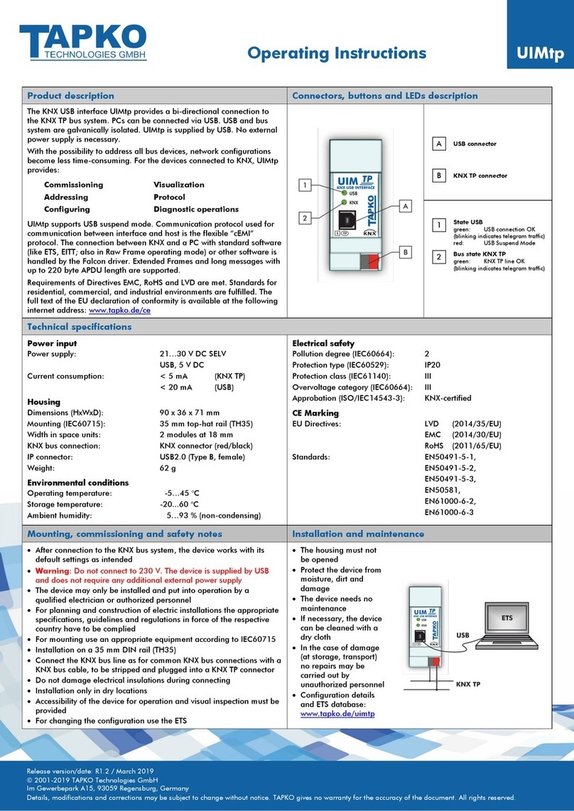
TAPKO UIMip SECURE User manual

Operating Instructions
UIMip
SECURE
Release version/date: R1.1 / December 2019
© 2001-2019 TAPKO Technologies GmbH
Im Gewerbepark A15, 93059 Regensburg, Germany
Details, modifications and corrections may be subject to change without notice. TAPKO gives no warranty for the accuracy of the document. All rights reserved.
Product description
Connectors, buttons and LEDs description
The KNX IP (Secure) Interface UIMip-Sec provides an IP connection to
KNX TP. It is suitable for connection of KNX IP (Secure) devices, a PC with
ETS, and Ethernet networks. KNXnet/IP (Secure) Tunneling is supported.
Secure Tunneling, Secure Commissioning, and IP Backbone Security can
be activated.
For KNX devices, UIMip-Sec provides commissioning, configuring,
visualization, protocolling and diagnostic operation. Operational states,
malfunction and faulty communication are indicated by LEDs. With the
Function button UIMip-Sec can be reset to default settings. Long
messages with up to 240 byte APDU length are supported. For IP
(Secure) Tunneling, four (password-protected) Tunneling channels are
available.
UIMip-Sec is shown as UPnP network device. A disengageable web front-
end can be accessed to read out device settings, remotely activate
functions and watch a 60 min busload history diagram. The bootloader
function enables remote firmware updates via IP/Ethernet.
UIMip-Sec is suitable for 35 mm DIN rails and installation in distribution
boards. Supplied by the KNX bus line, it does not require an external
power supply. KNX IP devices can be connected directly and via Ethernet.
Requirements of Directives EMC, RoHS and LVD are met. Standards for
residential, commercial, and industrial environments are fulfilled. The full
text of the EU declaration of conformity is available at the following
internet address: www.tapko.de/ce
State IP
green: Main line OK
Bus state KNX TP
green: Subline OK
Telegram traffic IP
green (blinking):
Telegram traffic
Telegram traffic KNX TP
green (blinking):
Telegram traffic
red (blinking):
Transmission error
Programming LED
red: Programming Mode active
red (blinking):
No IP connection
Ethernet connector
Programming button
Function button
KNX TP connector
Technical specifications
Power input
Power supply:
Current consumption:
Housing
Dimensions (HxWxD):
Mounting (IEC60715):
Width in space units:
KNX bus connection:
IP connector:
Weight:
Environmental conditions
Operating temperature:
Storage temperature:
Ambient humidity:
21…30 V DC SELV
< 20 mA
90 x 36 x 71 mm
35 mm top-hat rail (TH35)
2 modules at 18 mm
KNX connector (red/black)
Ethernet (RJ45, female)
68 g
-5…45 °C
-20...60 °C
5…93 % (non-condensing)
Electrical safety
Pollution degree (IEC60664):
Protection type (IEC60529):
Protection class (IEC61140):
Overvoltage category (IEC60664):
Approbation (ISO/IEC14543-3):
CE Marking
EU Directives:
Standards:
2
IP20
III
II
KNX-certified
LVD (2014/35/EU)
EMC (2014/30/EU)
RoHS (2011/65/EU)
EN50491-5-1/-2/-3
EN50581
EN60950-1
EN61000-6-2/-3
IEC60950-1
Mounting, commissioning and safety notes
Installation and maintenance
•After connection to the KNX bus system, the device works with its
default settings as intended
•Warning: Do not connect to 230 V. The device is supplied by the
KNX bus and does not require any additional external power supply
•The device may only be installed and put into operation by a
qualified electrician or authorized person
•For planning and construction of electric installations the appropriate
specifications, guidelines and regulations in force of the respective
country have to be complied
•For mounting use an appropriate equipment according to IEC60715
•Installation on a 35 mm DIN rail (TH35)
•Connect the KNX bus line as for common KNX bus connections with a
KNX bus cable, to be stripped and plugged into a KNX TP connector
•Do not damage electrical insulations during connecting
•Installation only in dry locations
•Accessibility of the device for operation and visual inspection must be
provided
•For changing the configuration use the ETS
•The housing must not
be opened
•Protect the device from
moisture, dirt and
damage
•The device needs no
maintenance
•If necessary, the device
can be cleaned with a
dry cloth
•In the case of damage
(at storage, transport)
no repairs may be
carried out by
unauthorized persons
•Configuration details
and ETS database:
www.tapko.de/uimip-
sec
•Device Certificate and Serial Number
are placed on a label sidely adhered.
For archiving, the certificate can be cut
off and removed. Afterwards, the cut-off
part can only be identified by
comparison of the Serial Number.
1
2
3
4
5
A
C
B
D

Betriebs-/Montageanweisung
UIMip
SECURE
Version/Veröffentlichung: R1.1 / Dezember 2019
© 2001-2019 TAPKO Technologies GmbH
Im Gewerbepark A15, 93059 Regensburg, Germany
Hier enthaltene Daten können sich ohne vorherige Ankündigung ändern. TAPKO garantiert nicht die Richtigkeit und Vollständigkeit des Dokuments. Alle Rechte vorbehalten.
Produktbeschreibung
Anschlüsse, Tasten und LEDs
Die KNX IP (Secure) Schnittstelle UIMip ermöglicht eine IP-Verbindung
zu KNX TP und ist geeignet zum Anschließen von KNX IP (Secure)-
Geräten, einem PC mit ETS und Ethernet-Netzwerken. KNXnet/IP
(Secure) Tunneling wird unterstützt. Secure Tunneling, Sichere
Inbetriebnahme und IP Backbone Sicherheit sind aktivierbar.
Für KNX-Geräte ermöglicht die UIMip Inbetriebnahme, Konfigurierung,
Visualisierung, Protokollierung und Diagnose. LEDs zeigen Betriebs-
zustände, Fehlfunktion und fehlerhafte Kommunikation. Mit der
Funktionstaste kann die UIMip zurückgesetzt werden. Extended Frames
und lange Telegramme mit bis zu 240 Bytes APDU werden unterstützt.
Für IP (Secure) Tunneling stehen vier (passwort-geschützte) Tunneling-
Kanäle zur Verfügung.
MECip-Sec wird im Netzwerk als UPnP-Gerät angezeigt. Ein abschaltba-
res Web-Frontend zum Auslesen aktueller Einstellungen, zum Aktivieren
von Funktionen und zum Verfolgen der Buslast (60 min) steht zur Ver-
fügung. Der Bootloader ermöglicht Remote-Firmware-Updates via IP.
MECip-Sec ist ein REG für 35 mm DIN-Schienen und für den Einbau in
einen Verteilerkasten vorgesehen. Das Gerät wird über die KNX-
Buslinie versorgt und benötigt keine externe Versorgung. KNX IP Geräte
können direkt angeschlossen oder über Ethernet verbunden werden.
Die Anforderungen der Direktiven EMC, RoHS und LVD sowie Standards
für Wohn & Gewerbebereiche als auch Industriebereiche werden erfüllt.
Der vollständige Text der EU-Konformitätserklärung ist unter der
folgenden Internetadresse verfügbar: www.tapko.de/ce
Status IP
grün: Hauptlinie OK
Busstatus KNX TP
grün: Nebenlinie OK
Telegrammverkehr IP
grün (blinkend):
Telegrammverkehr
Telegrammverkehr KNX TP
grün (blinkend):
Telegrammverkehr
rot (blinkend):
Übertragungsfehler
Programmier-LED
rot: Programmier-Modus an
rot (blinkend):
Keine IP-Verbindung
Ethernet-Buchse
Programmiertaste
Funktionstaste
KNX TP Anschluss
Technische Angaben
Versorgung
Eingangsspannung:
Stromverbrauch:
Gehäuse
Maße (HxBxT):
Montage (IEC60715):
Breite:
KNX Bus-Anschluss:
IP-Anschluss:
Gewicht:
Umgebungsbedingungen
Arbeitstemperatur:
Lagertemperatur:
Umgebende Feuchte:
21…30 V DC SELV
< 20 mA
90 x 36 x 71 mm
35 mm DIN-Schiene (TH35)
2 TE zu je 18 mm
KNX Klemme (rot/schwarz)
Ethernet-Buchse (RJ45)
68 g
-5…45 °C
-20...60 °C
5…93 % (nicht-kondensierend)
Elektrische Sicherheit
Verschmutzungsgrad (IEC60664):
Schutzart (IEC60529):
Schutzklasse (IEC61140):
Überspannungskategorie (IEC60664):
Freigabe (ISO/IEC14543-3):
CE Kennzeichnung
EU Direktiven:
Standards:
2
IP20
III
II
KNX-zertifiziert
LVD (2014/35/EU)
EMC (2014/30/EU)
RoHS (2011/65/EU)
EN50491-5-1/-2/-3
EN50581
EN60950-1
EN61000-6-2/-3
IEC60950-1
Montage, Inbetriebnahme und Sicherheit
Installation und Wartung
•Nach Anschluss an das KNX-Bussystem arbeitet das Gerät mit seinen
Standardeinstellungen wie vorgesehen
•Warnung: Nicht an 230V anschließen. Das Gerät wird vom KNX-Bus
versorgt und benötigt keine zusätzliche externe Stromversorgung
•Das Gerät darf nur von einer Elektrofachkraft oder autorisiertem
Fachpersonal installiert und in Betrieb genommen werden
•Bei der Planung und Errichtung von elektrischen Anlagen sind die
einschlägigen Richtlinien, Vorschriften und Bestimmungen des
jeweiligen Landes zu beachten
•Zur Montage ein geeignetes Werkzeug nach IEC60715 verwenden
•Auf geeignete DIN-Hutschienen (TH35) montieren
•Die KNX-Buslinie, wie für alle üblichen KNX-Anschlüsse, mit
abisoliertem KNX-Buskabel und KNX TP-Klemme anschließen
•Beim Anschließen nicht die elektrischen Isolationen beschädigen
•Installation nur bei trockener Umgebung
•Die Zugänglichkeit zum Gerät muss aus Gründen der Bedienbarkeit
und Inspektion stets gewährleistet sein
•Änderungen an der Konfiguration mit der ETS vornehmen
•Das Gehäuse darf nicht
geöffnet werden
•Gerät vor Feuchtigkeit,
Schmutz und
Beschädigung schützen
•Das Gerät ist
wartungsfrei
•Wenn nötig, das Gerät
mit einem trockenen
Tuch reinigen
•Bei Beschädigung (bei
Transport, Lagerung)
darf keine Reparatur
vorgenommen werden;
Gerät zurückschicken
•Konfiguration-Details
und ETS-Datenbank:
www.tapko.de/uimip-
sec
•Gerätezertifikat und Seriennummer
befinden sich auf dem seitlich
angebrachten Etikett. Zur Archivierung
kann das Zertifikat abgerissen werden.
Danach ist das Zertifikat nur noch durch
Vergleich der Seriennummer
zuordenbar.
1
2
3
4
5
A
C
B
D
Table of contents
Languages:
Other TAPKO Recording Equipment manuals
