Target SUPER TILEMATIC STM10100 Use and care manual

1
OPERATING INSTRUCTIONSAND PARTS LIST
INSTRUCCIONES DE OPERACIÓN YLISTADE PIEZAS
0A7583
Copyright © May, 2002 DBInc.
Printed in U.S.A.
17400 W. 119
th
Street
Olathe,Kansas 66061
Customer Service........ 800-288-5040
Corporate Office .......... 913-928-1000
Cust. Service Fax ........ 800-825-0028
Corporate Office Fax... 913-438-7951
Int’l. Fax ........................ 913-438-7938
Internet.....http://www.targetblue.com
SUPER TILEMATIC
MODELS:
STM10100 & STM10100SS
STM10150 & STM10150SS

2

3
EVERY MACHINE IS THOROUGHLYTESTED BEFORE LEAVING THE FACTORY. EACH MACHINE IS
SUPPLIED WITH ACOPY OF THIS MANUAL. OPERATORS OF THIS EQUIPMENT MUST READAND BE
FAMILIAR WITH THE SAFETY WARNINGS. FAILURE TO OBEY WARNINGS MAY RESULT IN INJURYOR
DEATH. FOLLOW INSTRUCTIONS STRICTLY TO ENSURE LONG SERVICE IN NORMAL OPERATION.
CONTENTS
SymbolDefinitions .....................................................................................................4 - 6
DecalDescriptions andLocations..............................................................................7 - 9
Safety Warnings - DOs & DO NOTs ..........................................................................10 - 11
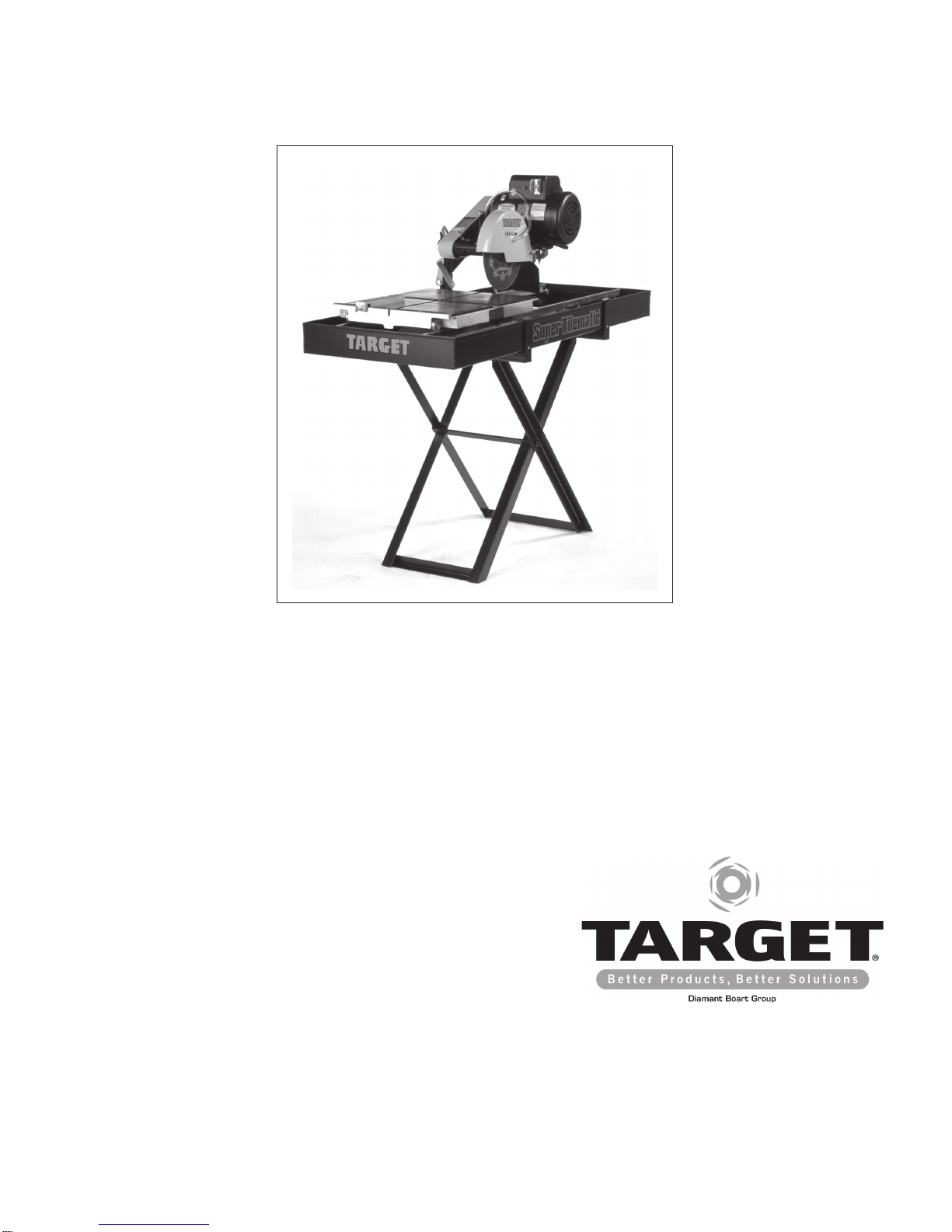
Reference Figure 1 ....................................................................................................12
Instructions:
1. Features ........................................................................................................13
2. Benefits .........................................................................................................13
3. Machine Set-Up Procedures..........................................................................13-14
4. OperatingProcedures ...................................................................................14-15
5. ManualThermal Overload..............................................................................15
6. ExtensionCords ............................................................................................15
7. AlignmentProcedures....................................................................................15-16
8. Profile Wheel Set-Up ..................................................................................... 16
9. Maintenance ..................................................................................................16
10.Water Pump, Trouble Shooting Procedure..................................................... 16
11. Repairs ..........................................................................................................17
12.Spare Parts ...................................................................................................17
13.Accessories ...................................................................................................17
Diagrams and Spare Parts ........................................................................................28-29
WiringDiagrams ........................................................................................................30-32
Warranty ....................................................................................................................33
ANTES DE SALIR DE NUESTRA FÁBRICA, CADAMÁQUINAES SOMETIDAAPUREBAS DETENIDAS. CADA
MÁQUINA DE CORTE ES ENTREGADA CON UNA CIPIA DE ESTE MANUAL. LOS OPERARIOS DE ESTOS
EQUIPOS DEBEN LEER YFAMILIARIZARSE CON LAS INSTRUCCIONES DE SEGURIDAD. ELNO PRESTAR
ATENCIÓNAESTASADVERTENCIASPUEDE OCASIONAR GRAVESLESIONE. SIGAESTRICAMENTE NUES-
TRAS INSTRUCCIONES Y SU MÁQUINA LE VA A PRESTAR LARGOS AÑOS DE SERVICIO EN CONDICIO-
NES NORMALES DE UTILIZACIÓN.
CONTENIDO
DefiniciónDe LosSimbolos .......................................................................................4 - 6
DescripciónDe CalcamoniasY Ubicaciones.............................................................7 - 9
AdvertenciasDe SeguridadHACER& NOHACER....................................................18-19
Figura 1 De Referencia..............................................................................................20
Instrucciones:
1. Caracteristica...............................................................................................21
2. Beneficio ......................................................................................................21
3. Instalacíon De La Cortadora ........................................................................22-23
4. InstruccionesDe Operación .........................................................................23
5. Protector Térmico - Rearmado Manual ........................................................24
6. CablesDe Extensión ....................................................................................24
7. Procedimientos deAlineacion .......................................................................24
8. Armado y Uso de la Rueda Perfiladora ........................................................25
9. InstruccionesDe Mantenimiento...................................................................25
10. EnCaso De Problemas Con La Bomba DeAgua ..........................................25
11. Reparaciones ...............................................................................................26
12. Piezas DeRecambio ....................................................................................26
13. Accesorios ...................................................................................................27
Diagrame y Piezas De Recambio ..............................................................................28-29
Diagrame De Cablado Eléctrico.................................................................................30-32
Garantia.....................................................................................................................33

4
SymbolDefinitions
Definición De Los Simbolos
• Please read the instructions for use prior to operating the machine for the first time.
• Antes de la puesta en marcha, lea detenidamente las instrucciones y familiaricese con la máquina.
• Mandatory
• Obligatorio
• Indication
• Indicación
• Prohibition
• Prohibición
• Warning Triangle
• Triángwulo DeAdvertencia
• Wear Eye Protection
• Usar Gafas De Protección
• Wear Head Protection
• Usar Casco De Protección
• Wear Breathing Protection
• Usar Máscara De Protección
• The Use Of Ear Protection Is Mandatory
• Es Obligatorio El Uso De ProtecciónAuditiva
• Wear a Hard Hat
• Usar Casco Duro
• Wear Safety Shoes
• UsarZapatos DeSeguridad
• WearAppropriate Clothing
• UsarRopaAdecuada
• RemoveTheBlade PriorToHoisting, Loading,UnloadingAndTransportingThe MachineOn Jobsite.
• Desmontar El DiscoAntes De Desplazar, Cargar, Descargar O Transportar La Máquina En La Obra.

5
•MotorOff
•Parar El Motor
•Use In Well Ventilated Area
•Usar En Una Área Bien Ventilada
•Do Not Use In Flammable Areas
•No Usar In Áreas Inflamables
•MachineryHazard,Keep HandsAnd FeetClear.
•Máquina Peligrosa - Mantenga ManosY PiesAlejados De La Máquina
•NoNon-working PersonnelInArea
•Prohibido Para PersonasAjenasALa Obra
•NoSmoking
•NoFumar
•Do Not Operate Without All Guards In Place
•No Operar Sin Todas Las Protecciones In Su Sitio
•Always Keep the Blade Guards In Place
•Mantenga Siempre Las Protecciones De La Hoja En Su Sitio
•Keep Work Area Clean/Well Lit, Remove All Safety Hazards
•Mantenga Limpio El Sitio De Trabajo/Bien Iluminado, Elimine Todos Los Riesgos De Seguridad
•DangerouslyHigh NoiseLevel
•NivelDe RuidoElevadamentePeligroso
•Pay ExtremeAttention To The CareAnd Protection Of The Machine Before Starting Up
•Ponga ExtremaAtención Al Cuidado Y Preparación De La MáquinaAntes De Ponerla En Marcha
•RemoveTools FromArea andMachine
•Elimine Las Herramientas Del Área Y De La Máquina
•Electrical Switch - OFF
•Conmutador DeApagado Eléctrico
•Electrical Switch - ON
•Conmutador De Encendido Eléctrico
•Electrical Switch - Start
•Conmutador DeArranque Eléctrico
•RepairsAre To Be Done ByAnAuthorized Dealer Only
•Las Reparaciones Deben Ser Efectuadas Únicamente Por Un DistribuidorAutorizado

6
•DiamondBlade
•SierraDiamantada
•BladeDiameter
•Diámetro De La Hoja
•PulleyDiameter
•Diámetro De La Correa
•Numberof RevolutionsPer Minute,RotationalSpeed
•N°De Revoluciones Por Minuto, Velocidad De Rotación
•BladeFlange Diameter
•Diámetro De La Brida De La Hoja
•BladeCutting Depth
•Profundidad De Corte De La Hoja
•Machine Mass (lbs)
•Masa De La Máquina (lbs)
•Electric Motor
•Motoreléctrico
WARNING
HEARINGHAZARD
DURINGNORMALUSE OFTHISMACHINE, OPERATORMAYBE EXPOSEDTOANOISE
LEVEL EQUAL OR SUPERIOR TO 85 dB (A)
ATENCION
RIESGO DE DAÑOAUDITIVO
ENCONDICIONES NORMALESDE UTILIZACIÓN,ELOPERADORDE ESTAMÁQUINAPUEDE
ESTAREXPUESTOAUNNIVELDE RUIDOIGUALO SUPERIORA 85 dB (A)

7
DECAL DESCRIPTIONS & LOCATION
DESCRIPCIÓN DE CALCAMONIAS Y UBICACIONES
P/N187043
Location: Belt Guard -Top
P/N046326
Location: Motor Assembly P/N046327
Location: Motor Assembly
P/N187691
Location: Belt Guard - Side

8
P/N189731
Location: Side of Belt Guard & Side of Blade Guard
P/N189734
Location: Water Pan Sides
DECAL DESCRIPTIONS & LOCATION
DESCRIPCIÓN DE CALCAMONIAS Y UBICACIONES
P/N189736
Location: Water Pan - Front

9
DECAL DESCRIPTIONS & LOCATION
DESCRIPCIÓN DE CALCAMONIAS Y UBICACIONES
P/N189731
Location: Blade Guard & Belt Guard - Side
P/N189734
Location: Side of SS Water Pan
P/N189736
Location: Front of SS Water Pan

10
DO read this entire operator’s manual before operating this machine. Understand all warnings, instructions, and controls.
DO keep all guards in place and in good condition.
DO wear safety approved hearing, eye, head and respiratory protection.
DO read and understand all warnings and instructions on the machine.
DO read and understand the symbol definitions contained in this manual.
DO keep all parts of your body away from the blade and all other moving parts.
DO know how to stop the machine quickly in case of emergency.
DO turn the “ON/OFF”switch to the “OFF”position prior to connecting the machine to the power source.
DO inspect the blade, flanges and shafts for damage before installing the blade.
DO use the blade flange size shown for each blade size.
DO use only the blade flanges supplied with the saw. Never use damaged or worn blade flanges.
DO use only blades marked with a maximum operating speed greater than the blade shaft speed. Verify speed by checking
blade shaft rpm and pulley diameters and blade flange diameters.
DO verify saw drive configuration by checking blade shaft RPM, pulley diameters, and blade flange diameter.
DO read all safety materials and instructions that accompany any blade used with this machine.
DO inspect each blade carefully before using it. If there are any signs of damage or unusual wear, DO NOT USE THE
BLADE.
DO mount the blade solidly and firmly. Wrench tighten the arbor nut.
DO make sure the blade and flanges are clean and free of dirt and debris before mounting the blade on the saw.
DO use the correct blade for the type of work being done. Check with blade manufacturer if you do not know if blade is
correct.
DO use caution and follow the instructions when loading and unloading the machine.
DO operate this machine only in well ventilated areas.
DO instruct bystanders on where to stand while the machine is in operation.
DO establish a training program for all operators of this machine.
DO clear the work area of unnecessary people. Never allow anyone to stand in front of or behind the blade while the motor
is running.
DO make sure the blade is not contacting anything before starting the motor.
DO use caution when lifting and transporting this machine.
DO always tie down the machine when transporting.
DO use caution and follow instructions when setting up or transporting the machine.
DO have all service performed by competent service personnel.
DO make sure electric powered machines are plugged into a properly grounded circuit.
DO make sure power cords are the proper size and in good condition.
DO maintain a secure grip on the material being cut.
DO clean the water tray frequently.
DO verify the blade arbor hole matches the machine spindle before mounting the blade.
DO clean the machine after each day’s use.
DO follow all electrical codes in your area.
DO consider work area environment. Don’t expose power tools to rain. Don’t use power tools in wet locations.
DO use caution to guard against electric shock. Prevent body contact with grounded surfaces (i.e., pipes, radiators, ranges,
refrigerators).
DO use correct voltage and proper extension cords. Never carry tool by cord or yank it to disconnect it from receptacle. Keep
cord away from heat, oil and sharp edges.
DO always carry the machine with the motor stopped.
DO disconnect tools from power source when not in use, before servicing and when changing accessories.
DO carefully maintain and clean for better and safer performance. Follow instructions for changing accessories. Inspect tool
cords periodically and, if damaged, have repaired by authorized service facility.
DO only cut in a straight line.
DO only saw as deep as the job specifications require.
DO always give a copy of this manual to the equipment user. If you need extra copies, call TOLL FREE 1-800-365-4003.
SAFETY FIRST!
WARNINGS
DO’sAND DO NOT’s
WARNING:FAILURE TO COMPLY WITH THESE WARNINGS AND OPERATING
INSTRUCTIONS COULD RESULT IN DEATH OR SERIOUS BODILY INJURY.
DO

11
DO NOT operate this machine unless you have read and understood this operator’s manual.
DO NOT operate this machine without the blade guard, or other protective guards in place.
DO NOT stand behind or in front of the blade path while the motor is running.
DO NOT leave this machine unattended while the motor is running.
DO NOT operate this machine when you are tired or fatigued.
DO NOT use a wet blade without adequate water supply to the blade.
DO NOT exceed maximum blade speed shown for each blade size. Excessive speed could result in blade breakage.
DO NOT operate the machine if you are uncertain of how to run the machine.
DO NOT use damaged equipment or blades.
DO NOT touch or try to stop a moving blade with your hand.
DO NOT cock, jam, wedge or twist the blade in a cut.
DO NOT transport a cutting machine with the blade mounted on the machine.
DO NOT use a blade that has been dropped or damaged.
DO NOT use carbide tipped blades.
DO NOT use abrasive blades.
DO NOT use conventional abrasive blades with water.
DO NOT touch a dry cutting diamond blade immediately after use. These blades require several minutes to cool after
each cut.
DO NOT use damaged or worn blade flanges.
DO NOT allow other persons to be near the machine when starting or when the machine is in operation.
DO NOT operate this machine in an enclosed area unless it is properly vented.
DO NOT operate this machine in the vicinity of anything that is flammable. Sparks could cause a fire or an explosion.
DO NOT allow blade exposure from the guard to be more than 180 degrees.
DO NOT operate this machine with the belt guard or blade guard removed.
DO NOT operate this machine unless you are specifically trained to do so.
DO NOT use a blade that has been over heated (Core has a bluish color).
DO NOT jam material into the blade.
DO NOT grind on the side of the blade.
DO NOT lay power cords in or near the water.
DO NOT replace the motor with any motor that does not have a special grounding connection.
DO NOT cut deeper than 1" per pass with a dry blade. Step out to achieve deeper cuts.
DO NOT start cutting with a saw until you have a clear work area and secure footing.
DO NOT operate this machine while using drugs or alcohol.
*****************
This saw was designed for certain applications only. DO NOT modify this saw or use for any application other
than for which is it was designed. If you have any questions relative to its application, DO NOT use the saw until
you have written Diamant Boart, Inc. and we have advised you.
Diamant Boart, Inc.
17400 West 119th Street
Olathe, Kansas 66061
In USA 1-800-365-4003
SAFETY FIRST!
WARNINGS
DO’sAND DO NOT’s
WARNING:FAILURE TO COMPLY WITH THESE WARNINGS AND OPERATING
INSTRUCTIONS COULD RESULT IN DEATH OR SERIOUS BODILY INJURY.
DO NOT

12
A. SetCollar
B. BearingCaps
C. LockingKnob
D. Lockbar
E. Water Pump
F. Hose Barb
G. Water Valve
H. Water TubeAssembly
I. Water Tube Ports
J. Blade Guard
K. ElectricalReceptacle
L. Blade ShaftNut
M. Outer Blade Flange
N. Wrench
O. DrainPlug
P. RipGuide
Q. Water PanAssembly Guides
1. Cutting HeadAssembly: Includes water tube
assembly(H)}
2. FrameAssembly
3. Water PanAssembly
4. Tow Cart Assembly Carton
5. Conveyor Cart Assembly Carton {Cart
Assembly (4) and Rip Guide (P)}
6. Water Pump andAccessory Carton: Includes
Water Pump (E), Hose Barb (F), Water Valve
(G), 15/16" Wrench (N), Drain Plug (P), Lock-
ing Knob (C) with 5/16" Flatwashers, Bearing
Caps (B) w/ 5/16”Fasteners and Set Collar
(A).
FIGURE 1

13
Use: Sawing of any kind of tile, up to 27" (685mm)
diagonal on 18" x 18" (450 x 450 mm) tile.
Tools: Rip Guide comes standard on all tile saws. See
Tile CuttingAccessories on page 15.
(For information or availability of other accessories
contact your Target supplier.)
Blade Capacity: Rim Ø10" (254mm) - bore 5/8"
(15,9mm).
Profile Wheel: Rim Ø7" (180mm) - bore 5/8" (15,9mm).
Blade Rotation: Counter-Clockwise (CCW).
Depth of Cut: 3-3/4" (95mm) with 10" (254mm) blade.
Horsepower: 1-1/2 1-1/2 2
Voltage: 115 115/230 240
F.L.Amperages: 14.6 17.2/8.6 12
Blade Shaft RPM: 2760 3880 2850
Weight: lb. (kg.) 150 (68.2) 154 (70) 171 (77.7)
Dimensions - L x W x H: in 51-1/4" x 25-3/4" x 19-3/4"
(cm) (130 x 65 x 50)
Conveyor Cart - with special rubberized surface.
L x W: in (mm) 10-1/4" x 16" (260 x 406)
Pan Holding Capacity: 12 gallons (46.1 liters)
These signs will give
advice for your safety
Before leaving our factory every machine is
thoroughly tested.
Follow our instructions strictly and your machine will
give you long service in normal operating conditions.
MANDATORY INDICATION
INFORMATION
INSTRUCTION
WARNING PROHIBITION
Any persons not involved in the work should
leave the area.
Use only blades marked with a maximum
operating speed greater than the blade shaft
speed.
•The new, improved blade guard offers simplified blade
installationand removal-maximum 10"(254mm)blade
capacity. Theexternalwatertubeassemblyisremovable
for easy maintenance.
•1-1/2 HP, High Torque (HT) 115V/60/1 motor on
standardsaw.
•The dependable, high volume, submersible coolant
pump features a screened intake.
•Themotorand pumppowercordsaresecurely mounted
directly into the Motor Housing (K).
•The removable Drain Plug (O) at the back end of the
pan permits easy coolant draining and quick sludge
clean out. The Water Pan (3) is removable for easy
cleaning.
•The free-rolling Conveyor Carts (4) are aligned for
straight, smooth cuts. The Back Stop with ruler allows
fast mounting and adjustment of the rip fence and
optional accessories.
•Full-sizebelt shield andbelt protection.
•The special, rubberized surface coating extends cart
life and aids in control of work.
•Makes 25" diagonal cuts on 18" x 18" (450 x 450 mm)
tile.
•The adjustable pan allows the operator to cut tile
comfortably with a full view and control of work with
minimumstretching.
(See Figure 1)
•Removeall itemsfrom theshippingcartonandidentify:
1. Cutting Head Assembly: Includes Water Tube
Assembly(H)
2. FrameAssembly
3. Water PanAssembly
4. Conveyor CartAssembly Carton {Cart Assembly
(4) and Rip Guide (P)}
5. Water Pump andAccessory Carton: Includes tile
markers, Water Pump (E), Hose Barb (F), Water
Valve (G), 15/16" Wrench (N), Drain Plug (O),
two Bearing Caps (B) and fasteners: [four each
of 5/16" flatwashers and fiber locknuts], Locking
Knob (C) and a 5/16" flatwasher.
6. LiteratureAssembly Envelope
NOTE:Checkthe carton andall packingfiller forloose parts
and optional accessories (if ordered).
•Set the Frame Assembly (2) on a flat surface or on a
TARGET ®folding stand.
Before starting up the machine, make sure you
read this entire manual and are familiar with
the operation of this machine.
Theworking area mustbe completelyclear, well
lit and all safety hazards removed.
The operator must wear
protective clothing
appropriate to the work he is
doing.
2 BENEFITS
3 MACHINE SET-UP PROCEDURE
1 FEATURES

14
•Mount the water pan assembly Guides (Q) over the
FrameAssembly(2) legsbetween thevertical postand
theSliding PanStop (R). ThePanAssembly (3)should
slide freely back and forth on the Guides (Q) with little
lateralmovement. Adjust ifneeded.
•Install the Cart Assembly (4) with the Back Stop at the
operating end. Check that all four wheels are on the
rails and that it travels freely back and forth.
Install the Cutting HeadAssembly (1):
1. Set the Cutting Head Assembly (1) on the pivot
bar up against the Set Collar (A). The set collar
has been pre-set at the factory to align the blade
with the slot in the center of the cart; it can be
adjusted if needed.
2. Install the two Bearing Caps (B) over the long
setscrewslocatedinthebottom oftheCutting Head
(1) using 5/16" flatwashers and locknuts. Next,
tightenthe locknutsso thatthe CuttingHead (1)is
held securely on the base pivot bar, but can be
adjusted up or down.
3. Insert the Locking Knob (C) with 5/16" flatwasher
through the slotted Lockbar (D) into the tapped
hole in the belt guard. This is used to set the
cutting depth of the blade.
Water Pump Assembly (5) Set-up:
1. Remove the Water Pump (E), Hose Barb (F), the
WaterControlValve(G) andWaterTubeAssembly
(H) from their carton. Thread the Hose Barb (F)
onthe water pumpoutlet, handtighten.
2. Slide theControlValve(G) ontothe flexibleplastic
tubingand pushthe openend ontothe HoseBarb
(F).
3. Set the Water Pump Assembly (5) in the deep
endof the panbeneath thebelt guard. Note: The
water pump inlet screen must be submerged
in order to properly pick up water.
4. Placethe WaterTubeAssembly (H)to theback of
theBlade Guard (J)and insertthe two1/4" plastic
nozzles into the Ports (I) on the side of the Blade
Guard (J). To prevent interference with the full
movement of the cart, it is recommended that the
tubingand electricalcordexit outthe backthrough
the indented area of the pan.
5. Insert themaleplug intothe Receptacle(K)on the
motor. The Water Pump (E) will start when the
motor is turned on. For dry cutting, the water
pumpshould beunplugged orremovedtoprevent
damageto the pump.
Install the Cutting Blade:
Always set the Motor Switch to OFF prior to
mounting the blade.
1. Be sure you are using the correct blade for the
materialbeing cut. Forexample, bladesare avail-
able for cutting materials such as wall tile, quarry
tile,marble, slateand similarlyhard materials.For
the best results, always use genuine TARGET ®
diamond blades. Contact your nearest dealer to
select the correct blade for your specific cutting
needs.
2. Rotate theBladeGuard (J)fully up,tightening the
wing nut if needed to hold it in the fully raised
position.
3. Remove the Blade Shaft Nut (L) and the Outer
BladeFlange (M).
4. Check the blade for Counter Clockwise rotation
(CCW) and install on the spindle shaft.
Rotation direction is indicated by an arrow on
one side of the blade. Make sure the blade con-
tact surfaces are clean.
5. Install the outer flange with the large diameter
against the blade. Tighten the Blade Shaft Nut
(L) with the 15/16" Wrench (N) provided.
6. Lowerthe BladeGuard (J)and retightenthe wing
nut to securely hold the guard in place.
•Install the Drain Plug (O) into the back end of the pan
andfill withclean wateruntil inletfilter ofwater pumpis
covered; about 12 gal. (46.1 l).
•AdjustthePanAssembly (3)to accommodatethe size
of the tile to be cut and to obtain the most comfortable
position for the operator.
1. When cutting smaller tile units, adjust the pan all
the way to the rear. The operator has full view
and control of the work with minimum stretching.
2. For cutting intermediate sized units, such as 8"
or 10" tile, the pan can be placed somewhere
betweenthemaximum forwardand maximumrear
positions.
3. When cutting larger units, the pan should be
moved to the maximum forward position, thus
givingthe operatorthe bestandmost comfortable
position, even when cutting 18" x 18" or larger
units.
WARNING: Read the Operating Procedure
completely before operating your tile saw.
Take into account the working conditions from
the health and safety point of view.
Always pay extreme care and attention to the
preparation of the machine before starting.
Remove all wrenches and tools from the
machine.
Always keeps blade guard in place.
•Fill the Pan with enough water to fully submerge the
water pump screen. It takes approximately 12 gallons
(46.1 l.) to fill the Pan.
•Before connecting the power cord:
* Checkthe spindlenut tobe sureit istightand that
the blade rotates freely.
4 OPERATING PROCEDURE

15
WARNING: Check that the ON/OFF switch is in
the OFF position. Then connect the power cord
to a properly grounded outlet of the correct
voltage. See the decal near the power cord for
power requirements. If needed, use the correct
size three (3) conductor extension cord to avoid
excessive voltage drop. Never use lamp cord
type extensions. Refer to the Recommended
Extension Cords chart below.
•Turn the switch to ON. The blade should turn counter-
clockwise, when looking at the blade guard side. The
waterpump willstartautomaticallywhenthemotorstarts.
Adjustmentof thewater supplymay bemadeby means
oftheControl Valve(G).
•Follow the blade manufacturer’s recommendations for
dry or wet cutting. Wet cutting blades can be damaged
or destroyed without sufficient water. Only blades spe-
cifically designed for dry cutting can be used without
coolant.
The water supply should be adequate, with
water flowing on both sides of the blade. Keep
the water clean and make certain the WATER
LEVER IS ALWAYS ABOVE THE PUMP INLET.
Do not run the water pump dry!! Unplug for dry
cutting.
•For straight cuts, position the tile squarely against the
back edge of the conveyor cart. Keep the cart clean
and free of cuttings. The standard rip guide is used.
•Move the conveyor cart slowly and carefully until the
blade is in contact with the tile. The blade needs a
chance to “break-in”or “wear-in”slightly. It may take
about ten cuts to open a new blade for best cutting.
Your Super Tilematic tile saw is factory assembled and
alignedprior toshipmentto ensureaccurate cutswhenyour
sawis delivered. However, sinceTARGET®cannotcontrol
rough handling during shipping, it is suggested that the
alignment be checked. If the saw is found in need of
adjustment,refer tothe appropriatesection(s) below.
There are two basic alignment checks for the Super
Tilematic and any adjustments made must follow these
procedures to ensure that the unit functions freely.
Adjustment tools required: Carpenter’s Square, two (2)
7/16" wrenches, 1/2" wrench and 5/32" hex key.
1. Check the Blade in SlotAlignment
* The blade should be centered in the conveyor
cart slot.
* Set-up your saw as described above and move
the conveyor cart back and forth from the front
tothe rearof thepan. If thebladecontacts either
side of the slot, the Cutting Head Location
Adjustmentmust beperformed.
Cutting Head Location Adjustment (See Figure)
* The Cutting HeadAssembly is located between
to Set Collars (S). Using a 5/32" hex key, loosen
these two (2) set collars. Next, loosen the four
(4)5/16"-18locknut nuts(1/2"wrench) thatclamp
the bearing caps (B) to the Pivot Bar (T). Move
the HeadAssembly along the bar until the blade
no longer contacts the slot. Re-locate the set
collarsagainstthesides oftheCutting Headagain
and retighten the set screws. Retighten the
locknuts on the bearing caps.
Good motor performance depends on proper
voltage. Extension cords that are too long
and/or too small in wire gauge reduce the
voltage to the motor under load. Use exten-
sion cords no smaller than indicated below.
2. Check the ParallelAlignment (See Figure)
* The conveyor cart should travel parallel to the
plane of the blade.
* Place a square rule against the backstop, lightly
incontactwiththeblade. The bladesurfaceshould
beparallel tothe square;i.e., nogap betweenthe
blade and the square at either the front or back
edgeof theblade. Next,holding thesquarefirmly,
The motor is equipped with a manual overload protection
reset button. If the motors overheats, the red reset button
will “pop out”to open the motor circuit; stopping the motor
and water pump. If this occurs , the motor ON/OFF switch
must be set to OFF. After the motor cools, push in the reset
button. When it stays in, the motor can be restarted.
7 ALIGNMENTPROCEDURES
5 MANUAL THERMAL OVERLOAD
6 RECOMMENDED EXTENSION CORDS
MOTOR F.L.AMPS 50' Cord 75' Cord 100' Cord
HP RPM 115V 230V 115V 230V 115V 230V 115V 230V
1-1/2 1725 14.6 #12 #10 #8
1-1/2 3450 17.2 8.6 #10 #14 #10 #14 #8 #14
2 3450 16.8 8.4 #10 #14 #10 #14 #8 #14
2 2850 12 #12 #10 #10

16
Before performing any maintenance, ALWAYS
place the machine on a level surface with the
motor OFF and disconnect the electrical
current. Let the machine cool down!!
Your TARGET®tile sawis aruggedly constructedmachine,
engineered to give long, satisfactory performance. Simple
daily maintenance and care will add to the life and produc-
tivity of your saw.
traverse the cart fore and aft. The blade should
remain parallel to the square, staying slightly in
contactwith itthroughoutits fulltravel. Ifthe blade
does not stay in contact with the square, the
Parallelalignment mustbe performed.
ParallelAlignment
* The parallel tracking of the cart can be adjusted
by moving the rails on which the cart travels. The
mounting holes in the pan and the Rail Support
(U)are slottedto accommodatethis adjustment.
* Align the inside rail first. Loosen the four (4)
1/4"-20 fasteners (7/16" wrenches) locating the
two(2) Rails(R) sothatboth railsare freetomove.
Move the end(s) of rail until the square is flush
with the blade as described above. Tighten the
fasteners of this rail and recheck the alignment.
Once alignment has been made, move the cart
fore and aft to locate the second rail parallel to
the first. Tighten the remaining two fasteners.
The Super Tilematic is designed for use with a TARGET®
6" Profile Wheel, such as P/N 621081 or 621082.
•Raise the blade guard. Remove the spindle nut and
outer flange. Remove the tile saw blade if one has
beeninstalled.
•Installtheprofile wheelontothespindle shaftupagainst
theinner flangewith theworkingsurface totheoutside.
•Secure into place by reversing the outer flange and
tightening the spindle nut. Lower the Blade Guard (J)
back down over the profile wheel.
•Locate the material for profiling:
1. Set the edge of the part to be shaped parallel to
thewheel.
2. Locate the material under the wheel. Pull the
Conveyor Cart (4) with the material from under
the wheel to set proper cutting height.
3. Loosen theLockingKnob (C)andlower theCutting
Head (1) so that the wheel just slightly makes
contactwith the material.
4. Securethe Cutting Head(1) intoposition withthe
Locking Knob (C) for cutting.
5. Note: Profiling usually takes several light passes
to produce the best results. Set lower each time
until the desire depth has been reached.
After each day’s use: CLEAN THE MACHINE!!
* Turn off and unplug the saw before performing
anymaintenance.
* Keep the cart top clean and free for cuttings. To
clean it, flush the top surface and grooves with
water.
* Drain, clean and refill the pan frequently. Flush
thecoolant systemwithplenty ofwater, thendrain
and refill the pan.
* If the water flow stops, check the water pump to
see if the shaft and impeller turn freely. See the
WATER PUMP TROUBLE-SHOOTING
PROCEDURE section.
* It is always good practice to clean your tile saw
after each day’s use. Drain the water and clean
out the pan. Clean the rails. Before storing, it is
good practice to wipe or spray rails with water-
soluble oil (like, WD-40 or equivalent).
Entrust all repairs to your authorized dealer
only.
If Water Stops Flowing,
1. Stop Sawing, then
2. Disconnect Electrical Plug from Outlet, then
3. Remove the Pump, then
4. Back Flush.
Back flushing is done by forcing water into the pump
discharge and out through the screen. Most of the time this
procedureworks, andthe pumpcanbe putbackintoservice.
(See Figure below)
If the back flushing does not work, remove the screen and
turn the impeller manually, looking for and rinsing out the
impeller cavity of any dirt or foreign matter.
8 PROFILE WHEELSET-UPAND USE
9 MAINTENANCEPROCEDURES
10 WATER PUMP TROUBLE-SHOOTING PROCEDURE

17
We carry out all repairs in the shortest possible time and at
the most economical prices. (See front page for address
and phone numbers) Contact your authorized TARGET®
dealer concerning maintenance and repairs.
Forquick supplyof spareparts andto avoidanylost time,it is
essentialto quotethedata onthemanufacturers platefixed to
the machine and the part number(s) and description to be
replacedwithevery order.
ANGLE GUIDE PROTRACTOR PRECISION MITERING GUIDE BULLNOSE FOLDING STAND
Parts List:
Diag. Part No. Qty. Description Diag. Part No. Qty. Description
1 161479 1 Frame,Miter 10 1 ProtractorArm
2 050107 1 Bar, Locking 11 020011 1 Bolt,Carriage, 1/4-20x 5/8”
3 050105 1 Clip, Stop 12 020244 1 Wing Nut, 1/4-20
4 050106 1 Spring 13 020598 1 Screw, Thumb, 1/4-20 x 1”
5 050103 1 Knob 14 051010 1 ProtractorAssy
6 020598 2 Screw, Thumb, 1/4" - 20 x 1" 15 020598 1 Screw, Thumb, 1/4" - 20 x 1"
7 051020 1 MiterAssy, 45°16 051030 1 Holder Assy, Bullnose
8 020598 1 Screw, Thumb, 1/4" - 20 x 1" 17 051041 1 Stand, Tile Saw
9———— 1 Protractor Head 18 050102 1 SupportAssy, Miter Frame
RIP GUIDE: P/N 051000 - The Rip Guide is a standard
accessory supplied with every tile saw. It is used to
providea repeatablepositionfor ripcuts untilrelocated. The
RipGuide clampsto themachinedbackstop ofthe conveyor
cart.
ADJUSTABLE PROTRACTOR: P/N 051010 - The Pro-
tractor can be used to rip cut known angles. The protractor
clampsto thebackstop.
ANGLE GUIDE : P/N 051020 - This is a non-adjustable
miterused toquicklyposition thetile at45degrees; eitheron
the left or right side. It is often used for repeated
diagonal rip cuts. TheAngle Guide clamps to the backstop.
BULLNOSE MITERING GUIDE: P/N 051030 - This is a
fixed guide that positions the tile for a 45 degree miter cut.
TheMitering Guideclamps tothe backstop.
PRECISION MITERING JIG: P/N 161480 - This is a 45
degree fixture that has an adjustable clamp to hold the tile
while miter cutting. The Mitering Guide clamps to the
backstop.
BOOMERANGLE: P/N 169525 - This plastic accessory
holds the tile at 45 degrees; locating two edges of the tile.
Usefulfor diagonalcuts oruniformly cuttingoffcorners. The
Boomerangleclampsto thebackstopwithtwo thumbscrews.
FOLDING STAND: P/N 051041 - This stable, one piece
stand brings a TARGET®tile saw to standing level for ease
of work. The stand conveniently folds flat for storage and
transporting.
The instructions for use and spare parts found in this
document are for information only and are not binding.
As part of our product quality improvement policy, we
reserve the right to make any and all technical
modifications without prior notice.
The manufacturer accepts no
responsibility caused by unsuitable
use or modifications.
11 REPAIRS
13 TILE CUTTINGACCESSORIES
12 SPAREPARTS

18
SI lea todo el manual antes de manejar esta máquina. Entienda todas las advertencias, instrucciones y controles.
SI mantenga siempre las protecciones en su lugar y en buenas condiciones.
SI siempre use protecciones aprobadas para los oídos, ojos, cabeza y respiración.
SI lea y entienda todas las advertencias e instrucciones sobre la máquina.
SI lea y entienda las definiciones de los símbolos que aparecen en este manual.
SI mantenga todas las partes de su cuerpo alejadas de la hoja y de todas las piezas móviles.
SI aprenda cómo parar la máquina rápidamente en caso de emergencia.
SI ponga el interrumpor en la posición OFF antes de corectarlo a la fuente de poda.
SI verifique que la hoja, las bridas y los ejes no estén dañados antes de instalar la hoja.
SI usar el tamaño de brida de hoja que se muestra para cada tamaño de hoja.
SI use sólo discos diamantados con núcleo de acero fabricados específicamente para cortadoras de concreto.
SI usar el tamaño de brida de hoja que se muestra para cada tamaño de hoja.
SI utilice hojas abrasivas, o bien, hojas diamantadas con centro de acero fabricadas para utilización en sierras para albañilería.
Verifique la velocidad comprobando las rpm del eje de la hoja y el diámetro de las poleas.
SI verifique la configuración del motor de la sierra, comprobando la velocidad (rpm) del eje de la hoja y los diámetros de las poleas.
SI lea toda la literatura e instrucciones de seguridad que acompañan a la hoja utilizada con esta máquina.
SI inspeccione cuidadosamente cada hoja antes de usarla. Si se observan señales de daño o desgaste poco común, NO USE LA
HOJA.
SI instale la hoja firmemente. Apriete la tuerca del eje con un aprietatuercas.
SI asegúrese que la hoja y las bridas estén limpias y libres de tierra y suciedad antes de instalar la hoja en la sierra.
SI utilice la hoja correcta para el tipo de trabajo que se vaya a ejecutar. En caso de dudas, consultar con el fabricante de la hoja.
SI tenga cuidado y siga las instrucciones cuando cargue y descargue la máquina.
SI maneje esta máquina solamente en lugares bien ventilados.
SI Indique a las personas dónde situarse mientras la máquina estáfuncionando.
SI establezca un programa de entrenamiento para todos los operadores de esta máquina.
SI despeje el lugar de trabajo de personas innecesarias. No permita que nadie se sitúe delante o detrás de la hoja mientras el motor
estáfuncionando.
SI asegúrese que la hoja no estéhaciendo contacto con ninguna cosa antes de arrancar el motor.
SI tenga cuidado al levantar y transportar esta máquina.
SI siempre amarre bien la máquina cuando la transporte.
SI sea duidadoso y siga las intrucciones al instalar o transportar la máquina.
SI deje que todos los trabajos de mantenimiento los haga personal especializado.
SI asegúrese de enchufar las máquinas eléctricas a un circuito debidamente conectado a tierra.
SI asegúrese que los cordones eléctricos sean del tamaño correcto y estén en buenas condiciones.
SI sujete bien el material que estácortando.
SI limpie la bandeja de agua frecuentemente.
SI antes de instalar la hoja, verifique que el agujero del eje de la hoja coincida con el eje portaherramienta de la máquina.
SI siempre buscar si hay cables eléctricos subterráneos antes de aserrar. En caso de dudas, llamar a la empresa de electricidad
local.
SI limpie la máquina diariamente.
SI cumpla con el reglamento eléctrico de su localidad.
SI tenga en cuenta el medio ambiente de la zona de trabajo. No exponga útiles eléctricos a la lluvia. no use útiles eléctricos en
lugares húmedos.
SI sea cuidadoso para evitar golpes eléctricos. Evite el contacto corporal con las superficies conectadas a tierra de protección
(como tuberías, radiadores, refrigeradores, etc.).
SI use el voltaje correcto y un cable de extensión adecuado. Nunca transporte la herramienta colgando del cable y nunca tire del
cable para desenchufarlo. Aleje el cable del calor, aceite y de las aristas filudas.
SI desenchufe los equipos cuando no los usa, antes de hacer mantenimiento y al cambiar accesorios.
SI limpie y efectúe un mantenimiento cuidadoso para obtener un rendimiento mejor y más seguro. Siga las instrucciones al cambiar
accesorios. Revise los cables del equipo con frecuencia y, si hay daños, hágalos reparar por un servicio autorizado.
SI sólo corte en línea recta.
SI sólo corte tan profundamente como las especificaciones del trabajo lo requieren.
SI siempre entregar un ejemplar de este manual al usuario del equipo. Si se necesitan ejemplares adicionales, lammar SIN CARGO
al 1-800-365-4003.
HACER
ADVERTENCIA: EL NO RESPETAR ESTAS ADVERTENCIAS E INSTRUCCIONES
DE OPERACION PUEDE PROVOCAR GRAVES LESIONES O LA MUERTE.
ADVERTENCIAS
HACER y NO HACER
¡SEGURIDAD ANTE TODO!

19
*****************
Esta sierra fue diseñada para ciertas aplicaciones solamente. NO la modifique ni utilice para ninguna otra aplicación
salvo aquéllas para las cuales fue diseñada. En caso de dudas respecto a su aplicación, NO use la sierra sin antes
haber consultado por escrito a Diamant Boart, Inc. y haber recibido nuestras indicaciones.
Diamant Boart, Inc.
17400 West 119th Street
Olathe, Kansas 66061
In USA 1-800-365-4003
NO haga funcionar esta máquina sin antes haber leído y entendido este manual.
NO maneje esta máquina sin tener la protección de la hoja u otras protecciones instaladas en su lugar.
NO se sitúe detrás del paso de la hoja mientras el motor estáfuncionando.
NO deje esta máquina desatendida mientras el motor estáfuncionando.
NO maneje esta máquina si estácansado o fatigado.
NO usar esta sierra para hacer cortes en húmedo.
NO utilice una hoja de corte húmedo sin tener el suministro adecuado de agua.
NO sobrepase la velocidad máxima indicada para cada tamaño de hoja. El exceso de velocidad puede causar la rotura de
lahoja.
NO trabaje con la máquina si tiene dudas sobre su funcionamiento u operación.
NO utilice equipos u hojas que estén dañados.
NO toque ni trate de parar con las manos una hoja en movimiento.
NO incline, atasque, encaje o tuerza la hoja en el corte.
NO transporte una máquina de corte con la hoja instalada.
NO use un disco que haya sufrido un golpe o caída.
NO use discos con puntas de carburo.
NO utilice discos abrasivos con agua convencionales.
NO toque una hoja diamantada de corte en seco inmediatamente después de usarla. Estas hojas se demoran varios
minutos en enfriarse después de cada corte.
NO use bridas de hojas que estén dañadas o desgastadas.
NO permita que nadie se acerque a la máquina durante la puesta en marcha o mientras la máquina estáfuncionando.
NO maneje esta máquina en un lugar encerrado a menos que tenga buena ventilación.
NO maneje esta máquina cerca de ningún objeto que sea inflamable. Las chispas podrían causar un incendio o una explo-
sión.
NO permita que la hoja sobresalga más de 180 grados del protector.
NO maneje esta máquina sin el protector de la correa o de la hoja.
NO maneje esta sierra sin estar capacitado para hacerlo.
NO utilice una hoja que se ha sobrecalentado (el núcleo tiene un color azulado).
NO atasque el material contra la hoja.
NO esmerile con el costado de la hoja.
NO deje los córdones eléctricos en o cerca del agua.
NO deje la máquina sola con el motor encendido.
NO cambie el motor por alguno que no tenga una conexión especial de tierra de seguridad.
NO maneje la sierra si estábajo la influencia de drogas o bebidas alcohólicas.
ADVERTENCIA: EL NO RESPETAR ESTAS ADVERTENCIAS E INSTRUCCIONES
DE OPERACION PUEDE PROVOCAR GRAVES LESIONES O LA MUERTE.
ADVERTENCIAS
HACER y NO HACER
¡SEGURIDAD ANTE TODO!
NO HACER

20
A. Collarde Sujeción
B. Sombreretes del Cojinete
C. Perilla de Traba
D. Barra de Fijación
E. Bomba deAgua
F. Lengüeta de Manguera
G. VálvuladeAgua
H. Conjunto de Tubería paraAgua
I. Puertos de la Tubería para Agua
J. Protector de la Hoja
K. ReceptáculoEléctrico
L. Tuerca del Eje de la Hoja
M. Brida Externa de la Hoja
N. Llave
O. Tapa del Drenaje
P. Guía para Corte Longitudinal
Q. Guías para el Conjunto de la Bandeja de
Agua
1. Conjunto del Cabezal de Corte; Incluye el
Conjunto de Tubería paraAgua (H)
2. Conjunto delMarco
3. Conjunto de la Bandeja deAgua
4. Caja del conjuncto del carro de remolque
5. Caja del Conjunto del Carro Transportador
{Conjunto del Carro (4) y Guía para Corte
Longitudinal(P)}
6. Caja de la Bomba deAgua y Accesorios {in-
cluyeBomba deAgua (E), Lengüeta deMan-
guera (F), Válvula de Agua (G), Llave de
15/16" (N), Tapa del Drenaje (P), Perilla de
Traba (C) Perilla de enclavamiento con
arandelas planas de 5/16" y collar de fijación
(A),Tapasde cojinete (B)con sujetadoresde
5/16 pulg.
FIGURA 1
This manual suits for next models
3
Table of contents
Languages: