Tascam SB-16D User manual

D01393500A
16in/16out Dante Stage Box
SB-16D
AD/DA Converter
OWNER’S MANUAL
取扱説明書
ENGLISH

oTASCAM is a registered trademark of TEAC Corporation.
oAudinate®, the Audinate logo and Dante are trademarks of
Audinate Pty Ltd.
www.audinate.com/patents
oOther company names, product names and logos in this
document are the trademarks or registered trademarks of
their respective owners.
2TASCAM SB-16D

IMPORTANT SAFETY INSTRUCTIONS
CAUTION: TO REDUCE THE RISK OF ELECTRIC SHOCK, DO NOT REMOVE COVER (OR BACK).
NO USER-SERVICEABLE PARTS INSIDE. REFER SERVICING TO QUALIFIED SERVICE PERSONNEL.
The lightning ash with arrowhead symbol, within equilateral triangle, is intended to alert the
user to the presence of uninsulated“dangerous voltage”within the product’s enclosure that may
be of sucient magnitude to constitute a risk of electric shock to persons.
The exclamation point within an equilateral triangle is intended to alert the user to the presence
of important operating and maintenance (servicing) instructions in the literature accompanying
the appliance.
CAUTION: SHOCK HAZARD DISCONNECT ALL POWER SOURCES
ATTENTION: DANGER DE CHOC. DÉCONNECTER TOUTES LES SOURCES D’ÉNERGIE
WARNING: TO PREVENT FIRE OR SHOCK HAZARD, DO NOT
EXPOSE THIS APPLIANCE TO RAIN OR MOISTURE.
For U.S.A.
Supplier's Declaration of Conformity
Model Number: SB-16D
Trade Name: TASCAM
Responsible party: TEAC AMERICA, INC.
Address: 10410 Pioneer Blvd., Unit #1, Santa Fe Springs,
California 90670, U.S.A
Telephone number: 1-323-726-0303
This device complies with Part 15 of the FCC Rules. Operation
is subject to the following two conditions: (1) this device may
not cause harmful interference, and (2) this device must accept
any interference received, including interference that may
cause undesired operation.
INFORMATION TO THE USER
This equipment has been tested and found to comply
with the limits for a Class B digital device, pursuant to Part
15 of the FCC Rules. These limits are designed to provide
reasonable protection against harmful interference in a
residential installation. This equipment generates, uses, and
can radiate radio frequency energy and, if not installed and
used in accordance with the instructions, may cause harmful
interference to radio communications. However, there is
no guarantee that interference will not occur in a particular
installation. If this equipment does cause harmful interference
to radio or television reception, which can be determined by
turning the equipment o and on, the user is encouraged to
try to correct the interference by one or more of the following
measures.
a) Reorient or relocate the receiving antenna.
b) Increase the separation between the equipment and
receiver.
c) Connect the equipment into an outlet on a circuit dierent
from that to which the receiver is connected.
d) Consult the dealer or an experienced radio/TV technician
for help.
CAUTION
Changes or modications to this equipment not expressly
approved by TEAC CORPORATION for compliance could void
the user’s authority to operate this equipment.
IN USA/CANADA, USE ONLY ON 120 V SUPPLY.
For Canada
THIS CLASS B DIGITAL APPARATUS COMPLIES WITH CANADIAN
ICES-003.
CET APPAREIL NUMERIQUE DE LA CLASSE B EST CONFORME A
LA NORME NMB-003 DU CANADA.
This product complies with the European
Directives request and the other Commission
Regulations.
This product complies with applicable UK
regulations.
1. Read these instructions.
2. Keep these instructions.
3. Heed all warnings.
4. Follow all instructions.
5. Do not use this apparatus near water.
6. Clean only with dry cloth.
7. Do not block any ventilation openings. Install in accordance
with the manufacturer’s instructions.
8. Do not install near any heat sources such as radiators, heat
registers, stoves, or other apparatus (including ampliers)
that produce heat.
9. Do not defeat the safety purpose of the polarized or
grounding-type plug. A polarized plug has two blades with
one wider than the other. A grounding type plug has two
blades and a third grounding prong. The wide blade or the
third prong are provided for your safety. If the provided
plug does not t into your outlet, consult an electrician for
replacement of the obsolete outlet.
10. Protect the power cord from being walked on or pinched
particularly at plugs, convenience receptacles, and the
point where they exit from the apparatus.
ENGLISH
TASCAM SB-16D 3
OWNER’S MANUAL

11. Only use attachments/accessories specied by the
manufacturer.
12. Use only with the cart, stand, tripod, bracket, or table
specied by the manufacturer, or sold with the apparatus.
When a cart is used, use caution when moving the cart/
apparatus combination to avoid injury from tip-over.
13. Unplug this apparatus during lightning storms or when
unused for long periods of time.
14. Refer all servicing to qualied service personnel. Servicing
isrequired when the apparatus has been damaged in any
way, such as power-supply cord or plug is damaged, liquid
has been spilled or objects have fallen into the apparatus,
the apparatus has been exposed to rain or moisture, does
not operate normally, or has been dropped.
i The apparatus draws nominal non-operating power from the
AC outlet with its POWER or STANDBY/ON switch not in the
ON position.
i The mains plug is used as the disconnect device, the
disconnect device shall remain readily operable.
i If you are experiencing problems with this product, contact
TEAC for a service referral. Do not use the product until it has
been repaired.
WARNING
i Products with Class 1 construction are equipped with a
power supply cord that has a grounding plug. The cord of
such a product must be plugged into an AC outlet that has
a protective grounding connection.
CAUTION
i Do not expose this apparatus to drips or splashes.
i Do not place any objects lled with liquids, such as vases,
on the apparatus.
i Do not install this apparatus in a conned space such as a
book case or similar unit.
i The apparatus should be located close enough to the AC
outlet so that you can easily grasp the power cord plug at
any time.
i If the product uses batteries (including a battery pack
or installed batteries), they should not be exposed to
sunshine, re or excessive heat.
i CAUTION for products that use replaceable lithium
batteries: there is danger of explosion if a battery is
replaced with an incorrect type of battery. Replace only
with the same or equivalent type.
CAUTION
i DO NOT REMOVE THE EXTERNAL CASES OR CABINETS TO
EXPOSE THE ELECTRONICS. NO USER SERVICEABLE PARTS
ARE INSIDE.
i IF YOU ARE EXPERIENCING PROBLEMS WITH THIS PRODUCT,
CONTACT THE STORE WHERE YOU PURCHASED THE UNIT FOR
A SERVICE REFERRAL. DO NOT USE THE PRODUCT UNTIL IT
HAS BEEN REPAIRED.
i USE OF CONTROLS OR ADJUSTMENTS OR PERFORMANCE OF
PROCEDURES OTHER THAN THOSE SPECIFIED HEREIN MAY
RESULT IN HAZARDOUS RADIATION EXPOSURE.
The nameplate is located on the top of the unit as shown below.
Front side
Nameplate
RACK-MOUNTING THE UNIT
Use the supplied rack-mounting kit to mount the unit in a
standard 19-inch rack, as shown below.
Remove the feet of the unit before mounting.
ATTENTION
iLeave 1U of space above the unit for ventilation.
iAllow at least 10 cm (4 in) at the rear of the unit for
ventilation.
4TASCAM SB-16D

For European Customers
Disposal of electrical and electronic equipment and
batteries and/or accumulators
(a) All electrical/electronic equipment and waste batteries/
accumulators should be disposed of separately from the
municipal waste stream via collection facilities designated
by the government or local authorities.
(b) By disposing of electrical/electronic equipment and
waste batteries/accumulators correctly, you will help save
valuable resources and prevent any potential negative
eects on human health and the environment.
(c) Improper disposal of waste electrical/electronic equipment
and batteries/accumulators can have serious eects on the
environment and human health because of the presence
of hazardous substances in the equipment.
(d) The Waste Electrical and Electronic Equipment
(WEEE) symbols, which show wheeled bins that
have been crossed out, indicate that electrical/
electronic equipment and batteries/accumulators
must be collected and disposed of separately
from household waste.
If a battery or accumulator contains more than
the specied values of lead (Pb), mercury (Hg),
and/or cadmium (Cd) as dened in the Battery
Directive (2006/66/EC, 2013/56/EU), then the
chemical symbols for those elements will be
indicated beneath the WEEE symbol.
Pb, Hg, Cd
(e) Return and collection systems are available to end users.
For more detailed information about the disposal of old
electrical/electronic equipment and waste batteries/
accumulators, please contact your city oce, waste
disposal service or the shop where you purchased the
equipment.
For China
“仅适用于海拔2000m以下地区安全使用”
“仅适用于非熱帯气候条件下安全使用”
“ 环境保护使用年限”
产品有毒有害物质或元素的名称及含量
机种: SB-16D 有毒有害物质或元素
品名 铅
(Pb)
汞
(Hg)
镉
(Cd)
六价铬
(Cr6+)
多溴联苯
(PBB)
多溴二苯醚
(PBDE)
1 CHASSIS部分 ○ ○ ○ ○ ○ ○
2 FRONT PANEL部分 ○ ○ ○ ○ ○ ○
3 螺丝部分 ○ ○ ○ ○ ○ ○
4 线材部分 ○ ○ ○ ○ ○ ○
5 PCB Assy部分 × ○ ○ ○ ○ ○
6 电源部分 × ○ ○ ○ ○ ○
7 附属品部分 × ○ ○ ○ ○ ○
8 LABEL部分 ○ ○ ○ ○ ○ ○
9 包装部分 ○ ○ ○ ○ ○ ○
○ :表示该有毒有害物质在该部件所有均质材料中的含有量均在 GB/T26572 标准规定的限量要求以下。
× :表示该有毒有害物质至少在该部件的某一均质材料中的含量超出 GB/T26572标准规定的限量要求。
(针对现在代替技术困难的电子部品及合金中的铅)
ENGLISH
TASCAM SB-16D 5

Introduction
Thank you very much for purchasing the TASCAM SB-16D
16in/16out Dante Stage Box.
Before using this unit, read this Owner’s Manual carefully so that
you will be able to use it correctly and enjoy working with it for
many years. After you have nished reading this manual, please
keep it in a safe place for future reference.
You can also download this Owner’s Manual from the TASCAM
website.
SB-16D
https://tascam.jp/int/product/sb-16d/docs
Features
o Supports 16 channels of analog line/mic inputs
o Supports 16 channels of analog line/mic outputs
o Supports remote control using the dedicated TASCAM IO
CONTROL application
i Gain control
i Phantom power on/o
i PAD on/o
i Other functions
o Dante included as a standard feature with support for
redundancy
o AES67 is also supported, so connection is possible with
Ravenna and other compatible network audio technologies
o Flexible routing is possible using Dante Controller
o Support for sampling frequencies and bit lengths up to
96kHz and 32-bit
o Inputs have phantom power, signal and overload LEDs
o Outputs have signal LEDs
o Supports redundant power input with AC and DC power
supplies
o Reference level can be set
o 3U rackmount size
Included items
This product includes the following items.
Take care when opening the package to avoid damaging the
items. Keep the packing materials for transportation in the
future.
Please contact the store where you purchased this unit if any
of these items are missing or have been damaged during
transportation.
o Main unit ................................................................................................x 1
o Power cords (for Japan/USA, Europe and Oceania)................x 3
o Rackmount ear (with installation screws) set ...........................x 1
o Rackmount screw kit..........................................................................x 1
o TASCAM ID registration guide........................................................x 1
o Owner’s Manual (this document) including warranty...........x 1
Contente
IMPORTANT SAFETY INSTRUCTIONS ..................................... 3
Introduction............................................................................. 6
Features.................................................................................... 6
Included items ......................................................................... 6
Conventions used in this manual ........................................... 7
Precautions for placement and use........................................ 7
Notes about power supplies................................................... 7
Beware of condensation ......................................................... 7
Cleaning the unit ..................................................................... 7
About TASCAM customer support service............................. 7
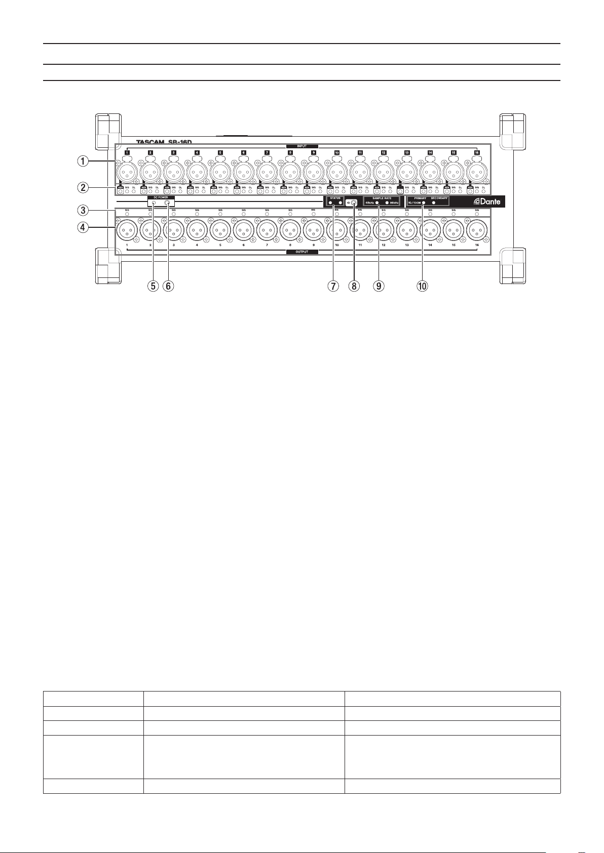
Names and functions of parts ................................................ 8
Front panel ...............................................................................................8
Rear panel .................................................................................................9
Left side panel .........................................................................................9
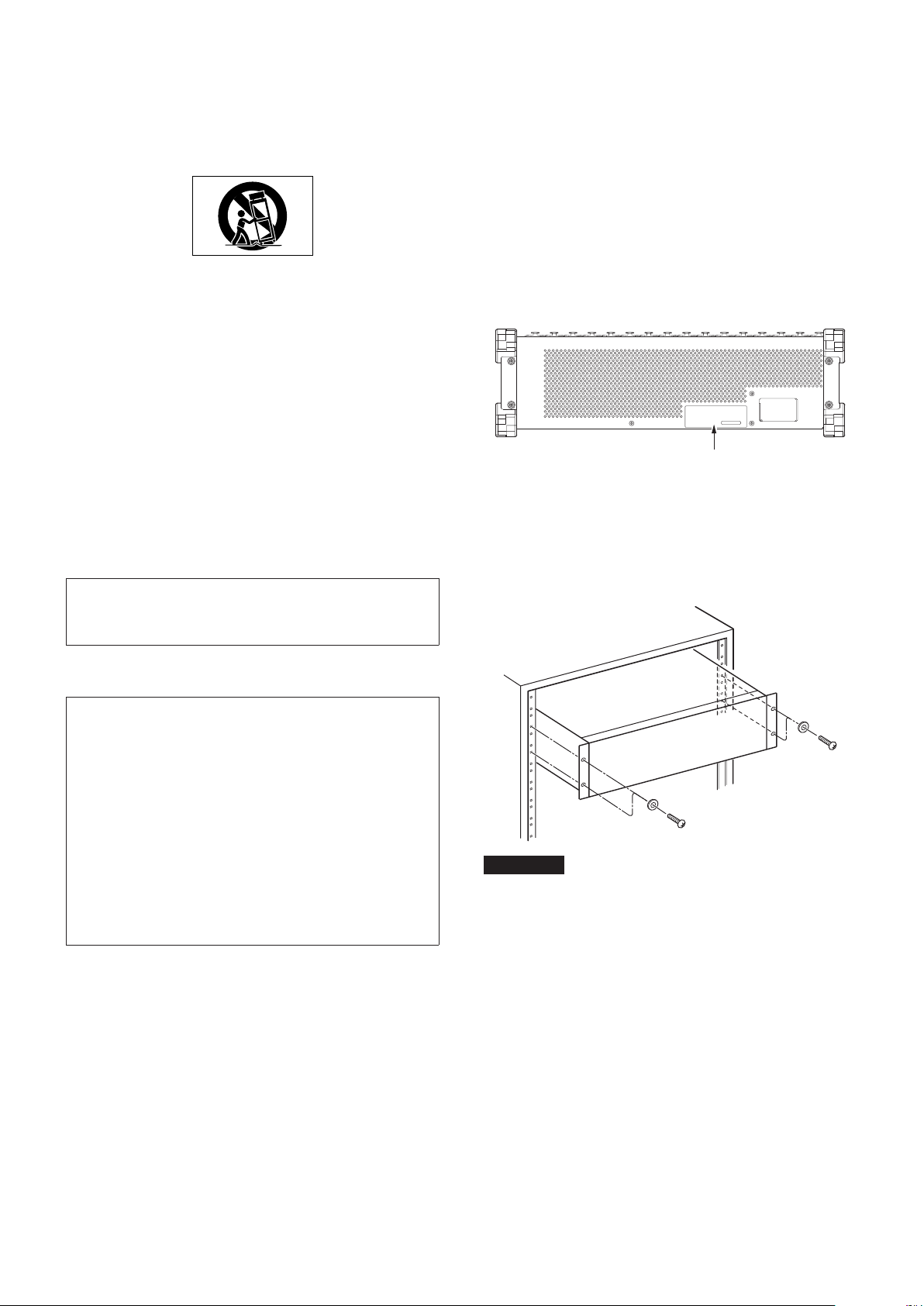
Attaching the rackmount ears.............................................. 10
Connecting the power........................................................... 10
Starting up when operating with only DC power supply..... 10
Notes about the DC POWER indicator......................................... 10
Application overview ............................................................ 11
Overview of settings ............................................................. 11
Setting mic/line inputs...................................................................... 11
Setting phantom power ................................................................... 11
Setting the reference level............................................................... 11
Device ID settings.................................................................. 11
Checking the device ID ..................................................................... 11
Changing the device ID .................................................................... 12
Restoring factory default settings ....................................... 12
Using as a Sonicview extension............................................ 12
Notes about Dante ................................................................ 13
Connecting to a Dante network ........................................... 13
Switched (daisy chain) connection............................................... 13
Redundant connection ..................................................................... 13
Using Dante Controller ......................................................... 14
Dante Controller overview............................................................... 14
Audio routing settings ...................................................................... 14
Changing sampling frequencies and bit depths with Dante
Controller ............................................................................................... 14
Control parameters ............................................................... 15
Parameter list........................................................................................ 15
GPIO connector overview ................................................................ 15
Specications and rated values............................................ 16
Audio performance ............................................................................ 16
Inputs and outputs............................................................................. 16
Other........................................................................................................ 16
Dimensional drawings .......................................................... 31
Software Licensing ................................................................ 32
6TASCAM SB-16D

Conventions used in this manual
In this manual, we use the following conventions:
o Additional information is introduced in the styles below
when needed:
TIP
These are tips about how to use the unit.
NOTE
These provide additional explanations and describe special
cases.
ATTENTION
Failure to follow these instructions could result in damage to
equipment or lost data, for example.
VCAUTION
Failure to follow these instructions could result in injury.
Precautions for placement and use
o The operating temperature range of this unit is 0 - 40 °C.
o Do not install this unit in the following types of locations.
Doing so could make the sound quality worse or cause
malfunction.
Places with signicant vibrations
Next to a window or in another location exposed to direct
sunlight
Near heaters or other extremely hot places
Extremely cold places
Very humid or poorly ventilated places
Very dusty places
o Do not block the ventilation ports, which dissipate heat, on
the back and sides of the unit.
o To enable good heat dissipation, do not place anything on
top of the unit.
o Do not place the unit on top of a power amplier or other
device that generates heat.
Notes about power supplies
o Insert the included power cord all the way into the AC IN
connector.
o Only connect a power supply that is AC100-240V (50–60Hz)
to the AC IN connector.
o Only connect a power supply that is DC 11V–27V to the EXT
DC IN connector.
ATTENTION
Use a power supply that has a 11V–27V Limited Power Source
(LPS) rating for output voltage with the EXT DC IN connector.
o Hold the power cord by its plug when connecting or
disconnecting it.
NOTE
This product includes 3 types of power cords. Use the power
cord that matches the type of power outlet being used.
Beware of condensation
Condensation could occur if the unit is moved from a cold place
to a warm place, it is used immediately after a cold room has
been heated or it is otherwise exposed to a sudden temperature
change.
To prevent this, or if this occurs, let the unit sit for one or two
hours at the new room temperature before using it.
Cleaning the unit
Use a dry soft cloth to wipe the unit clean. Do not wipe
with chemical cleaning cloths, thinner, alcohol or other
chemical agents. Doing so could damage the surface or cause
discoloration.
About TASCAM customer support
service
TASCAM products are supported and warrantied only in their
country/region of purchase.
To receive support after purchase, on the TASCAM Distributors
list page of the TEAC Global Site (https:// teac-global.com/),
search for the local company or representative for the
region where you purchased the product and contact that
organization.
When making inquiries, the address (URL) of the shop or
web shop where it was purchased and the purchase date are
required.
Moreover, the warranty card and proof of purchase might also
be necessary.
ENGLISH
TASCAM SB-16D 7

Names and functions of parts
Front panel
1Analog input connectors
These analog inputs are balanced XLR jacks.
i XLR (1: GND, 2: HOT, 3: COLD)
2INPUT SIG indicators
48V Indicators
These light when phantom power is on.
INPUT SIG indicators
These light when sound is being input through the
analog inputs.
Input is judged to have occurred when the signal level
exceeds -40 dBFS.
OL indicators
These light when analog input signals overload.
3OUTPUT SIG indicators
These light when sound is being output through the analog
outputs.
Output is judged to have occurred when the signal level
exceeds -40 dBFS.
4Analog output connectors
These analog outputs are XLR jacks.
i XLR (1: GND, 2: HOT, 3: COLD)
5DC POWER indicator
i This indicator will light when a DC power supply is
connected.
i This will blink to show that voltage is low when it
approaches the threshold voltage value set in advance on
the Sonicview 16/24 or using the TASCAM IO CONTROL
app.
See “Connecting the power”on page 10 for details.
6DC POWER button
i When operating only with DC power, press and hold this
button to turn the power on/o.
i Using this button is unnecessary when operating with AC
power because it will start up automatically.
See “Connecting the power”on page 10 for details.
7STATUS indicator
The STATUS indicator shows the state of the unit by lighting
blue or red or staying unlit.
See “STATUS indicator lighting status details”on page 8
for details.
8ID button
The device ID setting of this unit can be checked and
changed.
See “Device ID settings”on page 11 for setting procedures.
9SAMPLE RATE indicators
The lighting of the two SAMPLE RATE indicators (48 kHz/96
kHz) shows the sampling frequency state of the unit.
0PRIMARY/SECONDARY indicators
These light to show the Dante network status.
Communication is at 1 Gbps when lit and at 100 Mbps when
blinking.
STATUS indicator lighting status details
STATUS indicator Note
Ordinary operation Lit blue The unit is operating normally.
Malfunctioning (Dante) Rapidly ashing red (four times per second) The Dante module is malfunctioning.
Muted Lit red
The indicator lights red when the clock is stabilizing
after the unit starts up and when the sampling
frequency or other Dante setting has been changed,
for example.
Dante network error Flashing red (twice per second) The Dante network is not connected.
8TASCAM SB-16D

STATUS indicator Note
Dante redundancy error Blinking blue (once per second) The Dante PRIMARY connector is disconnected or
another error with redundant connection has occurred.
Update mode Blinking blue/red (once per second) The unit rmware is being updated.
Checking device ID
STATUS/SAMPLE RATE indicators and, according
to device ID number, OUTPUT channel LEDs blink
(once per second)
This is the state when the device ID set in the unit is
being shown.
Changing device ID
STATUS/SAMPLE RATE indicators and, according
to device ID number, OUTPUT channel LEDs blink
(twice per second)
This is the state when the device ID set in the unit is
being changed.
Safe mode STATUS/SAMPLE RATE/PRIMARY/SECONDARY LEDs
blink (once per second) The unit is in safe mode.
Rear panel
qRESET button
Pressing the RESET button while the unit is powered and
operating will restore network address settings and all other
unit settings to their factory defaults. (see “Restoring factory
default settings”on page 12)
wGPIO connector
This is a 25-pin D-sub Parallel control input/output
connector.
Use this to connect an external controller. (see “Dante
Controller overview” on page 14)
Left side panel
eAC IN connector
Connect the included power cord here.
rEXT DC IN connector
Connect external DC power here.
Use a power supply that has a 11V -27V Limited Power
Source (LPS) rating for output voltage with the EXT DC IN
connector.
The connector is XLR-4-32 (1: –, 2: NC, 3: NC, 4: +).
tPRIMARY connector
This is the main etherCON Cat5e-compatible Dante
transmission connector.
Use this to connect to a Dante network all the time.
ySECONDARY connector
This is the secondary etherCON Cat5e-compatible Dante
transmission connector. The use changes depending on the
mode.
When in redundant mode, this connects to the secondary
Dante network.
When in switched (daisy chain) mode, use to connect
another Dante device in the chain.
ENGLISH
TASCAM SB-16D 9

Attaching the rackmount ears
Before mounting this unit in a 19 inch rack, you must replace the
feet with the included rackmount ears. Follow these procedures
to attach the rackmount ears. (Prepare a Phillips screwdriver in
advance.)
1. Remove the 4 attached screws as shown in the illustration
below, and remove the 4 feet from the ends of the unit.
2. Attach the included rackmount ears to the unit using the
included rackmount ear installation screws.
NOTE
iReverse these procedures to reinstall the feet that were
originally attached to the unit.
iBy changing the attachment positions of the rackmount
ears, the unit can be mounted in a rack with its front panel
recessed by 20, 40 or 60 mm.
Furthermore, the rackmount ears can be attached
backwards.
Connecting the power
This unit has AC IN and EXT DC IN connectors, enabling
redundant power connection.
When both AC and DC power supplies are connected, the unit
will switch to the DC power supply if the AC power supply is cut,
preventing sound from being interrupted.
To use power supplies, connect them to the AC IN and EXT DC
IN jacks.
The unit can be used with power supplied to just one connector
or to both connectors simultaneously.
Starting up when operating with only DC
power supply
When operating with only DC power supply, the unit will not
start up just by supplying the power.
Press and hold the DC POWER (6) button for 5 seconds to start
the unit. To turn the unit o, press and hold the DC POWER (6)
button for 5 seconds.
NOTE
The unit will stay on when AC power is supplied. Moreover,
pressing and holding the DC POWER (6) button for 5
seconds will not shut down the unit.
Notes about the DC POWER indicator
o The DC POWER indicator (5) lights when the unit is on and
DC power is being supplied.
o This will become unlit when the DC power supply is less than
the set stop voltage. This will also be unlit when the unit is o.
o This will blink when below the set alert voltage.
o The stop voltage can be set between 11.0 V and 27 V in 0.1V
intervals. Set the stop voltage to the specications of the battery
that is supplying DC power. Set the stop voltage to 11.0 V when
the stop voltage specication is unknown or when using power
supplies other than batteries (including AC adapters).
o The alert voltage is set by default to a value that is 0.5 V
higher than the stop voltage. Adjust this setting as necessary
if the alert is shown too quickly or too late. The alert can also
be turned o.
o The stop voltage and alert voltage settings can be made
using external control by remote protocol, from the
Sonicview unit or from the TASCAM IO CONTROL app. Refer
to the following documents for details.--SB-16D remote
control specications
i Sonicview Series Reference Manual
i TASCAM IO CONTROL app operation manual
10 TASCAM SB-16D

Application overview
Using the TASCAM IO CONTROL application, the unit can be operated and its functions can be set remotely.
For details about the application, please see its Owner’s Manual.
The TASCAM IO CONTROL application and its operation manual can be downloaded from the TEAC Global Site (https://teac-global.com/).
For details about function that can be set, see “Parameter list” on page 15.
Overview of settings
Make various settings as necessary according to the connected equipment.
The following settings can all be made using the TASCAM IO CONTROL application. In addition, when used together with a Sonicview,
various settings can be made from the Sonicview. See“Using as a Sonicview extension”on page 12 for details.
Setting mic/line inputs
Mic and line input settings can be made.
Gain, pad and trim settings can also be made in these input settings.
Setting phantom power
Phantom power can be turned on when an external mic that requires it is connected to the unit.
This can be turned on/o independently for each channel.
ATTENTION
iBefore connecting condenser mics, turn this unit and all equipment to be connected o (standby).
iDo not connect or disconnect mics while phantom power is on. Doing so could cause a loud noise and might damage this unit and
connected equipment.
iTurn phantom power ON only when using a condenser microphone that requires phantom power. Turning phantom power on when
a dynamic mic or other mic that does not require it is connected could damage this unit and connected equipment.
iSupplying phantom power to some ribbon mics could break them. If unsure about a ribbon mic, conrm with the mic manufacturer
or do not supply phantom power to it.
Setting the reference level
You can set the analog input and output headroom (dierence between the maximum and reference levels).
Device ID settings
When using an SB-16D with a Sonicview 16/24, the device ID must be set to enable identication of the unit.
Follow the procedures below to check or change the device ID.
Checking the device ID
Press the ID (5) button.
The unit will enter device ID checking mode, and the STATUS and SAMPLE RATE indicators will blink.
INPUT SIG indicators and OUTPUT SIG indicators will light at the same time according to the device ID number.
The device ID is assigned by pairing the numbers of the input and output channel indicators.
For example, indicators will light for the following ID numbers as shown in the tables.
Device ID: #3-4
Channel number 1 2 3 4 5 6 7 8 9 10 11 12 13 14 15 16
INPUT SIG indicators 0
OUTPUT SIG indicators 0
Device ID: #15-8
Channel number 1 2 3 4 5 6 7 8 9 10 11 12 13 14 15 16
INPUT SIG indicators 0
OUTPUT SIG indicators 0
i Indicators that light when in device ID conrmation mode
ENGLISH
TASCAM SB-16D 11

Changing the device ID
Follow the procedures below to change the device ID.
ATTENTION
Be careful to set the device ID for this unit so that it is not the
same as another SB-16D connected to the same network.
1. Press and hold the ID (5) button for 10 seconds.
The STATUS and SAMPLE RATE indicators will light
simultaneously along with OUTPUT SIG indicators
according to the device ID number (twice per second).
2. When in device ID changing mode, press the ID (5) button
to change the device ID.
The blinking OUTPUT SIG indicator will change.
3. Press and hold the ID (5) button for 2 seconds to conrm.
After entering device ID changing mode, each time the ID (5)
button is pressed, the device ID will be increased by one (+1).
The blinking OUTPUT SIG indicator will also change in order
according to the device ID number.
After the OUTPUT SIG indicator reaches 16, pressing the ID (5)
button again will return to OUTPUT SIG indicator 1.
ATTENTION
When changing the device ID with this unit, changes with
OUTPUT SIG indicators 1–16 are possible.
To change INPUT SIG indicators, do so from a Sonicview
16/24 or using the TASCAM IO CONTROL application.
Restoring factory default settings
Pressing the RESET (9) button while the unit is powered and
operating will reset network address settings and all other unit
settings to their factory defaults.
Resetting Dante settings
Press and hold the RESET (9) button for 5 seconds.
The STATUS indicator will blink 2 times and the network address
and other settings for Dante will be restored to their default
values.
Resetting all settings made in the unit
Press and hold the RESET (9) button for 10 seconds.
The STATUS indicator will blink 3 times and all settings made in
the unit will be restored to their default values.
Launching the unit in safe mode
Connect a power supply while pressing the RESET (9) button.
This will start the unit in safe mode. The STATUS, SAMPLE RATE,
PRIMARY and SECONDARY indicators will blink twice per second.
Using as a Sonicview extension
By connecting this unit to the LAN of a Dante port in a TASCAM
Sonicview Series unit, this unit can be controlled from that
Sonicview. Moreover, mounting this unit on the TASCAM
Sonicview Series unit enables its analog inputs to be operated in
the same way as the analog inputs of the Sonicview.
Use the following procedures to mount it.
NOTE
iThese procedures assume that the Dante Control network
settings of this unit and the TASCAM Sonicview Series unit
are set to their defaults (Addressing is AUTO).
iA Sonicview can mount a maximum of 4 units.
1. Connect mics, speakers and other equipment with analog
connectors.
2. Connect the Dante ports of this unit and the Sonicview
Series unit with a LAN cable.
If the Dante setting for both devices is redundant mode,
connect the corresponding PRIMARY and SECONDARY
connectors of both units together.
See “Switched (daisy chain) connection”on page 13 and
“Redundant connection”on page 13 for connection
instructions.
3. Turn o the power of equipment connected to this unit.
4. Make the Dante routing setting.
By mounting this unit from the Sonicview unit, the Dante
routing between them will be set automatically. Moreover,
sampling rate, reference level, Dante latency and other
settings will automatically be set to suitable values.
For details, see the Reference Manual of the Sonicview
Series unit.
5. Make the Sonicview Series unit input and output routing
settings.
For details, see“5 – Routing”in the Reference Manual of the
Sonicview Series unit.
12 TASCAM SB-16D

Notes about Dante
Dante is a transmission protocol developed by Audinate.
Using networks based on gigabit Ethernet standards, it enables
multichannel (512 IN/512 OUT) transmission and high precision,
for example.
Check the Audinate website for details about Dante.
https://www.audinate.com/
Connecting to a Dante network
In order to set up and use this card, you must also set up the
Ethernet network that it is connected to, a computer that runs
Dante Controller and other devices that support Dante.
LAN cables used for connections
Use STP cables that are category 5e or higher.
Both crossover and straight cables can be used.
ATTENTION
This unit is not compatible with 100Mbps Ethernet switching
hubs. Always use switching hubs that support Gigabit
Ethernet.
NOTE
iWhen the Dante Network Addressing setting is AUTO (DHCP),
set the computer to set the IP address automatically.
iWhen the Dante Network Addressing setting is STATIC, set
the computer to match the Dante and network address.
Switched (daisy chain) connection
Dante devices can be daisy-chained when there are few
connected devices and when not using a switching hub.
Connect them as shown below.
Switched (daisy chain) connection example
SB-16D SB-16D
Mixer
NOTE
iWhen using a switched (daisy chain) connection, connect to
either the PRIMARY or SECONDARY connector.
iIf the number of connected devices increases, raising the
latency setting will be necessary.
Redundant connection
For recording situations where retakes are not possible,
including live performances, a connection set up like the
following uses two completely independent primary and
secondary networks.
Redundant connection example
SB-16D
HUB
PC
HUB
SB-16D
Primary Secondary
Mixer
NOTE
Settings for switched (daisy chain) and redundant
connections do not change automatically. Change the
settings on the Dante Controller Network Cong screen.
ATTENTION
The primary and secondary networks can never be
connected to each other by the same LAN (VLAN).
Hub
Primary
Secondary
ENGLISH
TASCAM SB-16D 13

Using Dante Controller
Dante Controller overview
This unit uses the Dante Controller application, which is
available at the Audinate website, to connect with other devices
that support Dante.
Download the latest version of the Dante Controller application
and an operation manual from the Audinate website.
Audinate download page
https://www.audinate.com/products/software/dante-
controller
Make at least the following settings using a computer that has
Dante Controller installed.
o Set the audio routing.
o Adjust the sampling frequency and bit depth of each Dante
device.
NOTE
Settings made using Dante Controller are stored in the built-
in memory of each Dante device.
Unless settings are modied, connections will not
change even if Dante Controller is quit or the computer is
disconnected from the Dante network.
Audio routing settings
When Dante Controller is launched, the Network View screen
shown below will open.
On this screen, you can set and monitor conditions related to
the Dante network.
1Receiving device name
This is the name of a receiving device on the Dante network.
2Receiving device channels
These are the names of the channels of the receiving device
on the Dante network.
3Transmitting device name
This is the name of a transmitting device on the Dante
network.
4Transmitting device channels
These are the names of the channels of the transmitting
device on the Dante network.
5Audio routing
Route the audio channels of the transmitting and receiving
devices that you want to connect here.
Click the intersection of the channels you want to connect
on the matrix to connect them.
NOTE
While pressing the computer keyboard Ctrl key, click the“-” at
the intersection of device names to connect all connectable
channels at once.
Changing sampling frequencies and bit
depths with Dante Controller
Double-click a device name on the Network View screen to open
the Device View screen.
On this screen, you can set and monitor conditions related to
devices on the Dante network.
Click the Device Cong tab to open the page where you can
change the sampling frequency, bit rate and other settings of
the device selected in 1shown in the illustration below.
1Device name
This is the name of the device that can have its settings
changed in the current Device View.
2Change device name
Edit the device name.
3Sampling frequency
Set the sampling frequency.
4Bit depth
Set the bit depth.
5Latency setting
Set the latency.
ATTENTION
Changing the name of a device will clear audio routing
settings. For this reason, we recommend changing device
names to names that are easy to identify before setting audio
routings.
14 TASCAM SB-16D

Control parameters
Parameter list
This unit has the following parameters.
They can all be controlled using a dedicated app and from a TASCAM Sonicview Series unit.
Function Notes
Head Amp GAIN adjustment
When Analog Reference Level = +6 dBu
When PAD OFF: +12 dB – +66 dB
When PAD ON: -8 dB – +46 dB
When Analog Reference Level = +4 dBu
When PAD OFF: +3 dB – +57 dB
When PAD ON: -17 dB – +37 dB
When Analog Reference Level = 0 dBu
When PAD OFF: +8 dB – +62 dB
When PAD ON: -12 dB – +42 dB
PAD ON/OFF -20 dB when on
PHANTOM ON/OFF +48V when on
Sampling rate setting 96 kHz (default)/48 kHz
Device name setting Set/change the device name as desired
Channel label settings Set/change channel names as desired
Switching the reference level Digital reference level settings -9 dBFs/-14 dBFs/-16 dBFs/-18 dBFs/-20dBFs (default)
Analog reference level settings +6dBu (when -9dBFs)/+4dBu (default)/+0dBu
Indicator brightness adjustment Setting range: 0–3 (default) (in 1 ms steps)
Identify Makes all SIG and STATUS indicators on the unit blink
Network settings
(Dante Primary/Dante
Secondary/SB-16D unit)
Static/Auto (DHCP) Automatic acquisition/manual setting for IP address
IP Address IP address can be set/changed when“Static”
Subnet Mask Subnet Mask can be set/changed when “Static”
Password setting Set/change password as desired (no password by default)
GPIO setting Set/change function assigned to GPIO connector
Preset setting Set presets
GPIO connector overview
The GPIO connector on the back is a parallel control connector
for conducting external control of this unit.
In addition to external control of the SB-16D, GPIO connector
functions can also be set for use as extensions of the TASCAM
digital mixer GPIO connector. These can be set using the
TASCAM IO CONTROL app or a TASCAM digital mixer that
supports connection with this unit.
To use this unit by itself, see“GPIO settings”in the TASCAM IO
CONTROL reference manual.
When connected to a TASCAM Sonicview Series unit, this can be
done on the GPIO-IN and GPIO-OUT pages of the USER DEFINED
CONTROL screen. For details, see“GPIO-IN page”and “GPIO-
OUT page”in“4 – Mixer conguration and other settings”of the
Reference Manual for the Sonicview Series unit.
The pin assignments are as follows.
Pin No. Function IN/OUT
1 GND -
2 GPIO IN 2 IN
3 GPIO IN 4 IN
4 GPIO IN 6 IN
5 GPIO IN 8 IN
6 NC -
7 NC -
8 NC -
9 GPIO OUT 2 OUT
10 GPIO OUT 4 OUT
Pin No. Function IN/OUT
11 GPIO OUT 6 OUT
12 GPIO OUT 8 OUT
13 NC -
14 GPIO IN 1 IN
15 GPIO IN 3 IN
16 GPIO IN 5 IN
17 GPIO IN 7 IN
18 NC -
19 NC -
20 GND -
21 GPIO OUT 1 OUT
22 GPIO OUT 3 OUT
23 GPIO OUT 5 OUT
24 GPIO OUT 7 OUT
25 +5V -
IN: For command input
i Internal circuit with +5V pull-up
i Operates with low signal input of 50 msec or longer
OUT: For command and tally output
i Internal circuit is open collector (10Ω output impedance)
i 20V dielectric strength, 35mA maximum current
+5V: 50mA maximum supplied current
ENGLISH
TASCAM SB-16D 15

Specications and rated values
Audio performance
0 dBu = 0.775 Vrms
Mic amp EIN (equivalent input noise)
-128 dBu or less
Frequency response
MIC/LINE IN to DANTE OUT
20 Hz - 20 kHz: +0 dB, -0.5 dB (48 kHz) (JEITA)
20 Hz - 40 kHz: +0 dB, -1.0 dB (96 kHz) (JEITA)
DANTE IN to LINE OUT
20 Hz - 20 kHz: +0 dB, -0.5 dB (48 kHz) (JEITA)
20 Hz - 40 kHz: +0 dB, -1.0 dB (96 kHz) (JEITA)
Dynamic range
110 dB or more (MIC/LINE to DANTE, PAD = OFF, A.Ref = +4
dBu, GAIN = 12, JEITA)
111 dB or more (DANTE to LINE OUT, 48 kHz sampling
frequency)
112 dB or more (DANTE to LINE OUT, 96 kHz sampling
frequency)
Distortion
0.002% or less (MIC/LINE IN to DANTE, Input at +4 dBu, PAD =
OFF, A.Ref = +4 dBu, GAIN = 12, JEITA)
0.002 % or less (DANTE to LINE OUT, Output at 0 dBFS, JEITA)
Crosstalk
100 dB or more (MIC/LINE to LINE OUT, 1 kHz sine wave, JEITA)
A.Ref: Analog Reference Level setting
Inputs and outputs
INPUT 1–16 jacks
Connectors: XLR-3-31 equivalent (1: GND, 2: HOT, 3: COLD)
Input levels:
Pad o
Maximum input level: +12 dBu (TRIM at minimum)
Minimum input level: −62 dBu (TRIM at maximum)
Pad on
Maximum input level: +32 dBu (TRIM at minimum)
Minimum input level: -42 dBu (TRIM at maximum)
Input impedance: 5.0 kΩ or higher
NOTE
+48V phantom power can be supplied to each MIC/ LINE
input jack separately.
OUTPUT 1-16 jacks
Connectors: XLR-3-32 equivalent (1: GND, 2: HOT, 3: COLD)
Output impedance: 100 Ω
Nominal output level:
+6 dBu (D.Ref: -9 dBFS, A.Ref:+6 dBu)
+4 dBu (D.Ref: -14/-16/-18/-20 dBFS, A.Ref: +4 dBu)
0 dBu (D.Ref: -18/-20 dBFS, A.Ref: 0 dBu)
Maximum output level:
+15 dBu (D.Ref: -9 dBFS, A.Ref: +6 dBu)
+18 dBu (D.Ref: -18 dBFS, A.Ref: 0 dBu)
+20 dBu (D.Ref: -20 dBFS, A.Ref: 0 dBu)
+18 dBu (D.Ref: -14 dBFS, A.Ref: +4 dBu)
+20 dBu (D.Ref: -16 dBFS, A.Ref: +4 dBu)
+22 dBu (D.Ref: -18 dBFS, A.Ref: +4 dBu)
+24 dBu (D.Ref: -20 dBFS, A.Ref: +4 dBu)
D.Ref: Digital Reference Level setting
A.Ref: Analog Reference Level setting
Dante PRIMARY/SECONDARY connectors
Connector: etherCON Cat5e compatible connector*
Transmission protocol: Dante
Gigabit Ethernet standard: 1000BASE-T (IEEE 802.3ab)
Cables: category 5e or faster STP cables
* etherCON is a registered trademark of Neutrik AG.
GPIO connector
Connector: 25-pin D-sub (8-in/8-out, female, inch-standard)
i See “GPIO connector overview”on page 15 for details
about GPIO connector and assignments.
Other
Power
AC 100-240V, 50/60Hz
External power supply (DC 11-27V/4-2A)
i DC voltage/current range: 11V/4A − 27V/2A
Power consumption
44W
Dimensions
With standard feet attached
4540. × 179.6 × 140.0mm (W × H × D)
With rackmount ears attached
482.8 × 132.0 × 120.0mm (W × H × D)
Weight
4.5 kg
Operating temperature range
0 - 40°C (32 - 104°F)
o Illustrations in this manual might dier in part from the
actual product.
o Specications and external appearance might be changed
without notication to improve the product.
16 TASCAM SB-16D

製品を安全に正しくお使いいただき、あなたや他の人々への危害や財産への損害を未然に防止するために、以下の注意事項を
よくお読みください。
P
すぐに機器本体の電源スイッチを切り、必ず電源プラグをコンセントから抜いてください。
異常状態のまま使用すると、火災・感電の原因となります。
お買い上げの販売店またはティアック修理センター(巻末に記載)に修理をご依頼ください。
N
電源プラグとコンセントの周りにゴミやほこりが付着すると、火災・感電の原因となります。
定期的(年1回くらい)に電源プラグを抜いて、乾いた布でゴミやほこりを取り除いてください。
=
コードが傷んだまま使用すると火災・感電の原因となります。
万一、電源コードが破損したら(芯線の露出、断線など)、お買い上げの販売店またはティアック修理センター
(巻末に記載)に交換をご依頼ください。
故障、火災、感電の原因となります。
隙間を空けないと内部に熱がこもり、火災の原因となります。
火災・感電の原因となります。
通風孔をふさぐと内部に熱がこもり、火災の原因となります。
C
内部に水が入ると火災・感電の原因となります。
Y
カバーを外す、または改造すると、火災・感電の原因となります。
内部の点検・修理は、お買い上げの販売店またはティアック修理センター(巻末に記載)にご依頼ください。
火災・感電の原因となります。
TASCAM SB-16D 17
日本語

P
コードが傷つき、火災・感電の原因や、引っ掛けてけがの原因になることがあります。
通電状態の放置やお手入れは、漏電や感電の原因となることがあります。
N
突然大きな音が出て、聴覚障害などの原因となることがあります。
異常が起きた場合は、すぐに電源プラグをコンセントから抜いて、完全に電源が切れるようにしてください。
それ以外の物を使用すると、故障、火災、感電の原因となります。
=
火災・感電やけがの原因となることがあります。
コードが傷つき、火災・感電の原因となることがあります。
必ずプラグを持って抜いてください。
O
感電の原因となることがあります。
V
5年に1度は、機器内部の掃除をお買い上げの販売店またはティアック修理センター(巻末に記載)にご相談
ください。
内部にほこりがたまったまま、長い間掃除をしないと火災や故障の原因となることがあります。
特に、湿気の多くなる梅雨期の前に行うと、より効果的です。なお、掃除費用については、ご相談ください。
18 TASCAM SB-16D

このたびは、TASCAM 16in/16out Dante Stage Box SB-16D
をお買い上げいただきまして、誠にありがとうございます。
ご使用になる前に、この取扱説明書をよくお読みになり、正しい取
り扱い方法をご理解いただいた上で、末永くご愛用くださいますよ
うお願い申し上げます。お読みになったあとは、本書をいつでも見
られる所に保管してください。
また取扱説明書は、TASCAMのウェブサイトからダウンロードす
ることができます。
https://tascam.jp/int/product/sb-16d/
docs
p 16チャンネル アナログライン/マイク入力対応
p 16チャンネル アナログライン出力対応
p 専用アプリケーション「TASCAM IO CONTROL」によるリモー
トコントロールに対応
o ゲインコントロール
o ファンタム電源のオン/オフ
o PADのオン/オフ
など
p Danteを標準搭載しリダンダントに対応
p AES67にも対応。RavennaなどAES67と互換のあるネット
ワークオーディオとも接続可能
p Dante Controllerを使用してフレキシブルなルーティングが可
能
p サンプリング周波数/ビット長:96kHz/32bitまで対応
p 入力:ファンタム電源/シグナル/オーバーロードLED
p 出力:シグナルLED搭載
p AC + DC電源の二重化電源入力に対応
p リファレンスレベルの設定が可能
p 3Uラックマウントサイズ
本製品の構成は、以下の通りです。
開梱は本体に損傷を与えないよう慎重に行ってください。梱包箱と
梱包材は、後日輸送するときのために保管しておいてください。
付属品が不足している場合や輸送中の損傷が見られる場合は、お買
い上げの販売店にお問い合わせください。
p 本体 .................................................................................................x1
p 電源コード(JAPAN USA / EUROPE / OCEANIA) ........x3
p ラックマウントアングル(取付用ねじ)セット ........................x1
p ラックマウントビスキット ...........................................................x1
p TASCAM ID登録ガイド ..............................................................x1
p 取扱説明書(本書、保証書付き) .................................................x1
フロントパネル .............................................................................21
リアパネル .....................................................................................22
DC電源のみで動作させる場合の起動方法 .................................23
DC POWERインジケーターの表示について............................23
マイク/ライン入力を設定する ..................................................24
ファンタム電源を設定する ..........................................................24
リファレンスレベルを設定する ..................................................24
デバイスIDを確認する..................................................................24
デバイスIDを変更する..................................................................25
スイッチド(デイジーチェーン)接続 .......................................26
リダンダント(二重化)接続 ......................................................26
Dante Controllerについて ........................................................27
オーディオ・ルーティング設定 ..................................................27
Dante Controller
サンプリングレート/量子化ビット数の変更 ...........................27
パラメーターリスト ......................................................................28
GPIO端子について .......................................................................28
オーディオ性能 .............................................................................29
入出力定格 .....................................................................................29
一般 .................................................................................................29
TASCAM SB-16D 19
日本語

本書では、以下のような表記を使います。
p 必要に応じて追加情報などを、「ヒント」、「メモ」、「注意」とし
て記載します。
本機をこのように使うことができる、といったヒントを記載し
ます。
補足説明、特殊なケースの説明などをします。
指示を守らないと、機器が壊れたり、データが失われたりする
可能性がある場合に記載します。
V
指示を守らないと、人がけがをする可能性がある場合に記載し
ます。
p 本機の動作保証温度は、摂氏0度〜 40度です。
p 次のような場所に設置しないでください。音質悪化の原因、ま
たは故障の原因となります。
振動の多い場所
窓際などの直射日光が当たる場所
暖房器具のそばなど極端に温度が高い場所
極端に温度が低い場所
湿気の多い場所や風通しが悪い場所
ほこりの多い場所
p 放熱のため、リアパネルやサイドパネルの通風孔をふさがない
でください。
p 放熱をよくするために、本機の上には物を置かないでください。
p パワーアンプなど熱を発生する機器の上に本機を置かないでく
ださい。
p 本機をラックにマウントする場合は、付属のラックマウントア
ングルを取り付けてから、付属のラックマウントビスキットを
使って、下図のように取り付けてください。なお、ラック内部
では、本機の上に1U以上のスペースを空けてください。
ラックマウントアングルの取り付け方法については、23ペー
ジ「ラックマウントアングルの取り付け」をご参照ください。
p 付属の電源コードをAC IN端子に奥までしっかりと差し込んで
ください。
p AC IN端子には、AC100V(50-60Hz)以外の電源には、接
続しないでください。
p EXT DC IN端子には、DC11V 〜 27V以外の電源を接続しな
いでください。
EXT DC IN端 子 に は、 出 力 電 圧 が11V 〜 27Vの 範 囲 内 で
Limited Power Source(有限電源)に適合する電源を使用し
てください。
p 電源コードの抜き差しは、プラグを持って行ってください。
本機には、3種類の電源コードが同梱されています。ご使用にな
る電源コンセントの形状に合った電源コードをご使用ください。
本機を寒い場所から暖かい場所へ移動したときや、寒い部屋を暖め
た直後など、気温が急激に変化すると結露を生じることがあります。
結露したときは、約1 〜 2時間放置してから電源を入れてお使いく
ださい。
製品の汚れは、柔らかい乾いた布で拭いてください。化学ぞうきん、
ベンジン、シンナー、アルコールなどで拭かないでください。表面
を傷める、または色落ちさせる原因となります。
p この製品には、保証書が添付(巻末に記載)されています。大
切に保管してください。万が一販売店の捺印やご購入日の記載
がない場合は、無料修理保証の対象外になりますので、ご購入
時のレシートなどご購入店・ご購入日が確認できる物を一緒に
保管してください。
p 保証期間は、お買い上げの日より1年です。保証期間中は、記
載内容によりティアック修理センター(巻末に記載)が無償修
理致します。その他の詳細については、保証書をご参照ください。
p 保証期間経過後、または保証書を提示されない場合の修理など
については、お買い上げの販売店またはティアック修理センター
(巻末に記載)にご相談ください。修理によって機能を維持でき
る場合は、お客様のご要望により有料修理致します。
p 万一、故障が発生した場合は使用を中止し、必ず電源プラグを
コンセントから抜いて、お買い上げの販売店またはティアック
修理センター(巻末に記載)までご連絡ください。修理を依頼
される場合は、次の内容をお知らせください。
なお、本機の故障、もしくは不具合により発生した付随的損害(録
音内容などの補償)の責については、ご容赦ください。
o 型名、型番(SB-16D)
o 製造番号(Serial No.)
o 故障の症状(できるだけ詳しく)
o お買い上げの年月日
o お買い上げの販売店名
p お問い合わせ先については、巻末をご参照ください。
p 本機を廃棄する場合に必要となる収集費などの費用は、お客様
のご負担になります。
20 TASCAM SB-16D
Other manuals for SB-16D
2
Table of contents
Other Tascam Media Converter manuals

Tascam
Tascam FW-1804 User manual

Tascam
Tascam LA-40MKIII User manual

Tascam
Tascam US-16X08 Use and care manual

Tascam
Tascam CD-A580 User manual

Tascam
Tascam ML-32D User manual

Tascam
Tascam SB-16D User manual

Tascam
Tascam iU2 User manual

Tascam
Tascam MM-2D-E User manual

Tascam
Tascam FW-1884 User manual

Tascam
Tascam Dante AE-4D User manual
Popular Media Converter manuals by other brands

Alloy
Alloy AC Series user manual

LSC
LSC MDR Series Operator's manual

Baumer
Baumer HOG 16 M + DSL Installation and operating instructions

FrSky
FrSky CPPM instruction manual

CORNING
CORNING OptiTect Gen III Series quick start guide

Omnitron Systems Technology
Omnitron Systems Technology OmniConverter GPoE+/S user manual