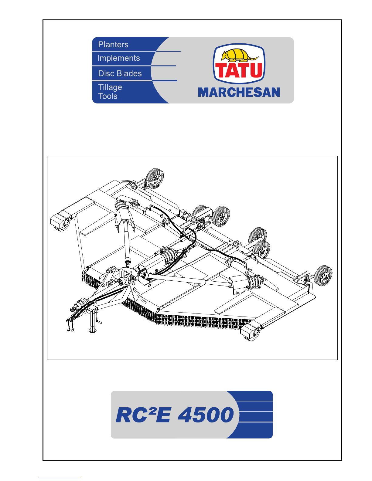
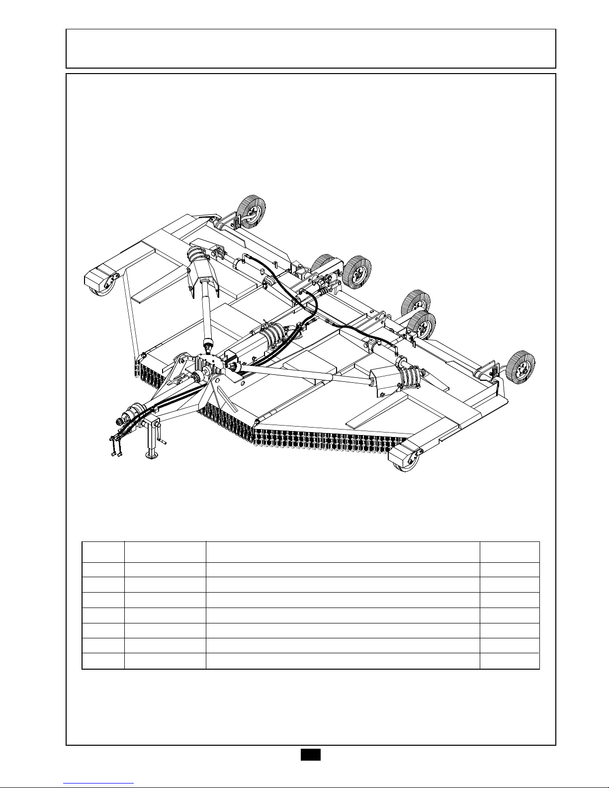
TATU RC2E 4500 User manual

INSTRINSTR
INSTRINSTR
INSTRUCTIONS MANUUCTIONS MANU
UCTIONS MANUUCTIONS MANU
UCTIONS MANUALAL
ALAL
AL

1
TATU RC²/E 4500 Rotary Cutter makes the mowing operations with better efficiency
and high quality.
The advanced design and the great working width allow reduction around to fifty
percent in the operational cost; especially in the cleaning of citric and similar orchards,
in the elimination of crop remains and services that demand quickness in its
accomplishment.
Especially designed for extensive areas, the RC²/E 4500 model possesses a central
frame and two highly resistant lateral frames, in order to act in severe situations. The
articulations allow to follow the ground surface contours, maintaining the even cutting
height in all its long range.
The cutting blades operates in an overlapped way, avoiding the formation of non
mowing strips.
Equipped with direct transmission, the gearboxes (Multipliers and Divider) are
protected by slip clutches; offering larger useful life and low maintenance cost.
The heavy-duty structure possesses beams in the upper surface of the rotary cutter,
avoiding the earth accumulation in the lower surface.
This Manual contains the necessary information for the best rotary cutter
performance. The Operator should read with attention the whole Manual before starting
the rotary cutter operation and be sure of understanding all safety recommendations.
To get any elucidation, or in the eventuality of technical problems, consult the Dealer,
as well as Marchesan's customer service, that will guarantee the rotary cutter full
operation.
INTRODUCTIONINTRODUCTION
INTRODUCTION

2
INDEXINDEX
INDEXINDEX
INDEX
TO THE OWNER ................................................................................................................... 3
General Information ............................................................................................. 3
TO THE OPERATOR ...................................................................................................... 4 to 9
Operation Safety........................................................................................ 4 and 5
Transporting on Truck or Trailer ............................................................................ 6
Safety Stickers ............................................................................................. 7 and 8
Location of the Stickers ......................................................................................... 9
TECHNICAL SPECIFICATIONS .......................................................................................... 10
COMPONENTS.................................................................................................................. 11
PREPARATION FOR USE ........................................................................................... 12 to 18
Attaching to Tractor................................................................................... 12 to 14
Putting in the Transport Position ......................................................................... 14
Putting in the Working Position ........................................................................... 15
Mounting the Indicator of Oil Level With Vent .................................................. 16
Transverse Leveling ............................................................................................. 17
Front-to-Rear Leveling......................................................................................... 18
ADJUSTMENTS AND OPERATIONS ......................................................................... 19 to 24
Reversion of the Outboard Tires ........................................................................ 19
Articulation of the Wings .................................................................................... 19
Cutting Height Adjustment ................................................................................ 20
Main Driveshaft ................................................................................................... 21
Direction of Blades Rotation and Part Number................................................ 22
Slip Clutch ............................................................................................................ 23
OPERATIONS - Important Points ......................................................................... 24
MAINTENANCE........................................................................................................ 25 to 28
Lubrication ........................................................................................................... 25
Lubrication Points ................................................................................................ 25
Reversion or Replacement of the Blades ............................................ 26 and 27
Replacement of the Skid Guides....................................................................... 27
Procedures Before Storing the Rotary Cutter for a Long Period ..................... 28
Procedures to Come the Rotary Cutter Back for Operation .......................... 28
IMPORTANT .......................................................................................................................29

3
TO THE OWNERTO THE OWNER
TO THE OWNER
IMPORTANT: - ONLY A PERSON WHO OWNS A FULL KNOWLEDGE OF THE TRACTOR AND
IMPLEMENT, MUST OPERATE THEM.
- MARCHESAN IS NOT RESPONSIBLE FOR ANY DAMAGE CAUSED BY
ACCIDENT ON TRANSPORT, INCORRECT UTILIZATION OR NO ADEQUATE
STORAGE.
- AFTER THE OPERATING SEASON, THOROUGHLY CLEAN YOUR IMPLEMENT
AND INSPECT IT. PREVENTIVE MAINTENANCE PAYS DIVIDENDS.
- YOUR DEALER HAS ORIGINAL EQUIPMENT PARTS WHICH ASSURE PROPER
FIT AND BEST PERFORMANCE.
Note: THE WARRANTY SHALL NOT BE APPLIED TO ANY EQUIPMENT, OR ANY PART THEREOF,
WHICH HAS BEEN ALTERED ELSEWHERE THAN AT THE PLACE OF MANUFACTURE OR
WHICH THE ORIGINAL PURCHASER THEREOF, AT RETAIL, HAS USED OR ALLOWED
TO BE USED PARTS, NOT MADE OR SUPPLIED BY MARCHESAN S/A.
General information
- The right-hand and left- hand sides of the cutters are determinated by facing in
the direction the implement will travel when moving forward.
- When ordering parts please be sure to inform the quantity, part number and name
of each part wanted. It is also important to give the machine Serial Number, which is
placed on the mainframe.
The acquisition of any TATU product assures to the original purchaser the following rights:
- Warranty certificate.
- Instructions manual.
- Technical assistance by the dealer on the equipment delivery.
- The owner has obligation to inspect the conditions of the product on delivery, as
well as knowing the warranty terms.
- Special attention should be given to safety recommendations, operation cares
and maintenance of the product.
- The instructions provided in this manual indicate the best use and allows to reach
maximum efficiency, increasing the useful life of this product.
- This manual should be directed to the operators and maintenance people.

4
TO THE OWNERTO THE OWNER
TO THE OWNER
Dear User !
Respect the Ecology.
Do not throw the trash away.
This gesture of goodwill helps to
protect our Environment.
Do not spill combustible oil, battery and
filter residues in the soil. The trash in contact
with the soil reach the sub layer which
cause directly damage to the
Environment. Look for information to
delivery these contaminated elements to
whom knows how to recycle or re-use
them.
Be careful with the environment.
Operation Safety
- ONLY WITH A COMPLETE CO-OPERATION OF IMPLEMENT OPERATOR THE
ACCIDENTS CAN BE PREVENTED.
- THIS SYMBOL IS A WARNING DEVICE WHICH SHOULD BE KEPT IN A CLEAN
AND VISIBLE PLACE, WHEN TRANSPORTING THE IMPLEMENT DURING THE DAY
OR NIGHT. USE ACCESSORY LIGHTS AND OTHER DEVICES IN ORDER TO GIVE
ADEQUATE WARNING TO OPERATORS OF OTHER VEHICLES
The rotary cutters are easy to operate, therefore some basic and indispensable
cares are required on their handling.
Have always on mind that safety requires constant attention, observation and
prudence during the operation, transport, maintenance and storage of the machine.
Read and
understand the
information
before realize
adjustments and
maintenance.

5
TO THE OPERATO THE OPERA
TO THE OPERATORTOR
TORTOR
TOR
Never use your
hands to check
hydraulic leaks.
Escaping hydraulic
oil under pressure
may have sufficient
force to penetrate
the skin causing
personal injury.
Never attempt to
change the
adjustments, clean
or lubricate the
implement when in
movement.
Be careful when
moving around
steep graders to
avoid overturn.
Be careful with the
use of fertilizer or
chemicals.
These products in
contact with skin
may cause
personal injury.
Keep the
entrances and
places acessible to
work, clean and
free of the oil and
grease to prevent
accidents.
Never allow riders
on the tractor or
implement unless
an additional seat is
available.
Use extreme
caution when
circulating with the
implement under
electrical power
lines, any contact
may result in severe
shock, injury or
death.
In order to protect
yourself always
wear adequate
clothes and shoes
during the
operations.
Never transport
the implement on
rough roads during
the night. When
operating avoid to
make sharp turns
that may cause tire
to make contact
with implement.
When working
near the PTO Shaft
have a special
care.
Never come closer
to rotating parts.

6
TO THE OPERATO THE OPERA
TO THE OPERATORTOR
TORTOR
TOR
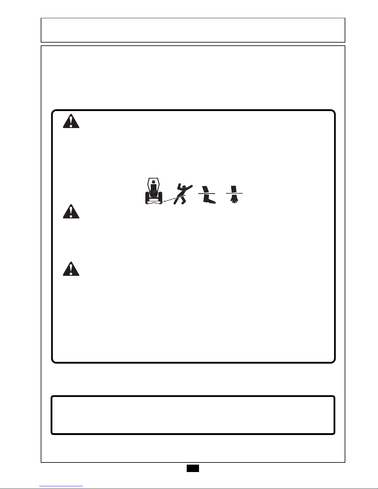
- During the operation or transport do not allow riders on the tractor or
implement. Serious personal injury could result from falling in the path of the
machine while in operation or transport.
- Never allow children playing near the place that you are operating in.
- Learn about the area before starting the operation. Delimit the dangerous
places or the obstacles.
- Use the most appropriate speed according to the land conditions or roads
to travel.
- Use individual equipments for your own protection.
- Wear clothes and adequate shoes. Avoid large or loosen clothes that could
twine on the movable parts.
- Never operate without the machine protection devices.
- Be careful when hitching the implement to the tractor. Hands or fingers can
be injured when caught between the hitch and tractor drawbar.
- Before starting to raise or move the implement check for people or animals
near or under the implement.
- Verify with attention the transport width in narrow places.
- When disconnecting the implement move it to level area, preferably a hard
surface, on the field or at the warehouse. Certify that the implement is properly
stationed.
- See the general safety instructions in the back-cover of this Manual.
When Transporting the Implement on Truck or Trailer
To transport the equipment at long distances use a truck or trailer. However,
the safety instructions should be followed carefully:
- Use adequate loading dock to load and unload the equipment. Never use
a ditch bank, this practice could result in serious personal injury.
- In the event of lifting up with hoist use the appropriate points to hold.
- Immobilize the implement properly.
- Use chock blocks and safety chains to secure the implement to the truck or
trailer during the transport.
- After 8 to 10 km transporting, please inspect the condition of the cargo.
Repeat this procedure every 80 to 100 km. Give more attention when
transporting the implement on rough roads, steep graders and other adverse
conditions.
- Be careful with transport height, specially when passing under electrical
power lines, etc... Any contact could result in severe shock, injury or death.
- Observe all laws and regulations as to the height limits and cargo width while
transporting the implement on truck or trailer. If necessary use banners, lights
and other devices in other to give adequate warning to the drivers of other
vehicles.

7
TO THE OPERATO THE OPERA
TO THE OPERATORTOR
TORTOR
TOR
SAFETY STICKERS
The safety stickers must be maintained in good shape of preservation. If the safety
stickers are damaged, or get illegible, they must be replaced. Marchesan will supply
the stickers by means of solicitation and indication of the respective codes.
0503031841 - Revisão 0 - 01/03
CAUTION CUIDADO
Rotary Cutters can throw fragments away at high-speeds, which can cause serious injuries or death for people
near around.
Don’t operate the Rotary Cutter with people around.
Las Desmalezadoras pueden soltar fragmentos en alta velocidad, lo que puede causar heridas graves para personas
próximas.
No opere la Desmalezadora con personas alrededor.
- In order to prevent serious personal injury read and understand the manual.
- Keep the belts and transmissions tighten and clean.
- Lower the implement, shut the engine off and remove the key from the tractor before uncoupling or servicing under the implement.
- Keep alert to stop the tractor and the implement immediately in case of emercency.
- Unqualified people and children are not allowed to operate this equipment.
- Be careful with uneven terrain and reduce the speed in sharp turns.
- Never operate the machine in transport position.
- Lea el manual de instrucciones antes de operar y siga todas las recomendaciones.
- Mantenga libre los locales de correas y transmisiones en general.
- Baje el equipo, pare el motor y retire la llave del tractor antes de desenganchar o trabajar en el equipo.
- Sepa como detener inmediatamente el tractor y el equipo en caso de emergencia.
- Personas no calificadas y niños están prohibidas de operar este equipo.
- Cuidado con terrenos irregulares. Disminuya la velocidad en curvas.
- Nunca opere la desmalezadora en la posición de transporte.
KEEP AWAY - ROTATING BLADES
Any contact or stone fragments thrown with action of the Blades could result in serious personal injury or death.
Never allow riders on the machine or near it while in operation.
MANTENGASE DISTANTE - CUCHILLAS ROTATIVAS
Lesión personal grave o muerte pueden resultar de fragmentos o contacto con las cuchillas.
No permanezca cerca ni suba en la Desmalezadora cuando esté en funcionamiento.
WARNING ADVERTENCIA
DANGER PELIGRO
0503031828
LUBRICATE AND TIGHTEN DAILY.
LUBRICAR Y REAPRETAR DIARIAMENTE.

8
TO THE OPERATO THE OPERA
TO THE OPERATORTOR
TORTOR
TOR
CACA
CACA
CAUTIONUTION
UTIONUTION
UTION
AA
AA
ATENCITENCI
TENCITENCI
TENCIÓÓ
ÓÓ
ÓNN
NN
N
Read the manual before attempting
to work with the equipment.
Lea el manual antes de iniciar el uso
del equipo.
0503031779
IMPORTANT
IMPORTANTE
DO NOT ADJUST THE FRICTION BEFORE
READING THE INSTRUCTIONS MANUAL.
NO AJUSTE LA FRICCION ANTES DE
LEER EL MANUAL DE INSTRUCCIONES.
0503031837
SAE 90 (ISO 220)
GEAR OIL.
LUBRICATE AND TIGHTEN
DAILY.
LUBRICAR Y REAPRETAR
DIARIAMENTE.
ACEITE SAE 90
(ISO 220).
0503031835
When working near the PTO Shaft have a
special care.
Never come closer to rotating parts.
Al operar con la toma de fuerza tenga el
máximo cuidado. No se aproxime al estar
en funcionamiento.
0503031784
WARNINGWARNING
WARNINGWARNING
WARNING
ADAD
ADAD
ADVERVER
VERVER
VERTENCIATENCIA
TENCIATENCIA
TENCIA
A

9
B
A
A
G
C
C
D
E
F
TO THE OPERATO THE OPERA
TO THE OPERATORTOR
TORTOR
TOR
Location of the Stickers
Item Code Description of Stickers Qty.
A 0503061386 Set of Stickers RC²E 4500 04
B 0503031784 Power Take Off 01
C 0503031841 Dangerous Rotary Blades 02
D 0503031837 Important Friction Adjustment 01
E 0503031779 Read the Manual with Attention 01
F 0503031835 Lubricate Daily 01
G 0503031828 Lubricate Daily 01

10
TECHNICAL SPECIFICATECHNICAL SPECIFICA
TECHNICAL SPECIFICATIONSTIONS
TIONSTIONS
TIONS
Model ..................................................................................................................... RC2/E 4500
Working Width (mm) ............................................................................................... 4,500 mm
Number of Blades ................................................................................................................06
Cutting Height (Adjustable)............................................................................... 50 - 310 mm
............................................................................................ Drawbar
..................................................................................................... PTO
.................................................................... Hydraulic Connections
Blade Rotation at 540 PTO rpm ............................................................................. 1,038 rpm
Number of Tires..................................................................................................................... 06
Type of Tires............................................................................................................ Laminated
.................................................................................................. 150 down
................................................................................ 200 up - (Operation)
................................................................................... 870 up (Transport)
Average Working Speed ..................................................................................... 4 to 6 Km/h
Tractor Engine Requirement ......................................................................................... 70 hp
Net Weight ................................................................................................................. 1,880 Kg
Total Width ............................................................................................................... 4,700 mm
Transport Width ....................................................................................................... 2,750 mm
Height .......................................................................................................................... 600 mm
Transport Height ...................................................................................................... 2,000 mm
Length ...................................................................................................................... 4,150 mm
Transport Speed ........................................................................................................ 25 Km/h
Front Wheels .........................................................................................................................02
Type of the Front Wheels .................................................................................................Steel
Tractor Coupling {
Wing Angles {
Attention: - THE ROTARY CUTTERS ARE DESIGNED FOR AGRICULTURAL APPLICATION AND
CAN'T WORK IN URBAN AREA.

11
01 11
04
03
09
08
02
05
06
07
10
12
13
01 - Deck
02 - Tongue
03 - Jack
04 - Driveshaft with Guard
05 - Slip Clutch
06 - Triple Divider Gearbox
07 - Multipliers
COMPONENTSCOMPONENTS
COMPONENTS
08 - Guards
09 - Cylinders
10 - Front Wheels
11 - Laminated Tires
12 - Safety Chains
13 - Hoses

12
A
A
PREPPREP
PREPPREP
PREPARAARA
ARAARA
ARATION FOR USETION FOR USE
TION FOR USETION FOR USE
TION FOR USE
Note: AFTER COUPLING THE CUTTER TO THE TRACTOR DRAWBAR, REMOVE THE JACK (A)
AND STORE IN THE FRAME, AS ILLUSTRATE BELOW.
Hitching to the Tractor
In order to hitch choose an area as flat as possible.
1st) Drawbar:
If possible, work with the tractor drawbar in the shortest position.
- Attach the cutter to the drawbar using the hitch pin and cotter pin. Use the
jack (A) which possesses adjustment to raise or to lower the tongue, in order to
facilitate the coupling.

13
05 cm
05 cm
PREPPREP
PREPPREP
PREPARAARA
ARAARA
ARATION FOR USETION FOR USE
TION FOR USETION FOR USE
TION FOR USE
2º) Power Take-Off
Verify the length of the driveshaft in the following way:
- Separate the male bar from the female tube and couple it to the power take-off.
- Position the tractor in an angle alignment until the tire approaches the drawbar.
- With the drive shaft bars placed side by side verify the existence of a minimum
free space of 05 centimeters on each end.
- If it is necessary, cut similar parts of the male and of the female drive shaft as
well as the guards.
Note: AT THIS TIME, IT CAN BE USED THE ADJUSTMENT RANGE OF THE TRACTOR DRAWBAR
FOR SHORTENING IT OR LENGTHENING IT.
Note: IT IS IMPORTANT TO GIVE FINISH WORKING IN THE CUT PARTS. FOR THIS PURPOSE
USE A MILL FILE. SOON AFTER, REMOVE THE FILLING AND LUBRICATE THE MALE
WITH A FINE LAYER OF GREASE.

14
AB
3rd) Hydraulic outlets:
- Finally connect the males of the
quick-couplers to tractor hydraulic
outlets (Two Control Valves) verifying
the adequate cleanliness.
PREPPREP
PREPPREP
PREPARAARA
ARAARA
ARATION FOR USETION FOR USE
TION FOR USETION FOR USE
TION FOR USE
Note: FOR BETTER ROTARY CUTTER
ACTING, IT IS NECESSARY
THE USE OF DOUBLE
CONTROL WITH FOUR REAR
OUTLETS.
NEVER WORK THE POWER TAKE-OFF WITH THE ROTARY CUTTER IN THE TRANSPORT
POSITION.
Putting in the Transport Position
- Work the wing lift cylinders and place the transport safety locks (A).
- Work the hydraulic cylinder of the tires and place the transport safety lock (B).

15
A
B
C
PREPPREP
PREPPREP
PREPARAARA
ARAARA
ARATION FOR USETION FOR USE
TION FOR USETION FOR USE
TION FOR USE
Putting in the Working Position
- Remove the transport safety locks (A) retracting a little the hydraulic cylinders
and removing the cotter pins (B).
- Lower the wings to rest on tires.
- During operation the safety
locks (A) must be fastened to the
wings.
- Also remove the wheels safety lock (C),
of the hydraulic cylinder, attaching to the
disuse position.
WHEN LOWERING THE WINGS, AVOID PEOPLE OR
ANIMALS TO COME CLOSER.

16
AB
C
Minimum
Maximum
D
Vent
Vent
Vent
Vent
PREPPREP
PREPPREP
PREPARAARA
ARAARA
ARATION FOR USETION FOR USE
TION FOR USETION FOR USE
TION FOR USE
Mounting the Indicator of Oil Level With Vent
- Triple Divider:
Place the valve with vent (A),
supplied with the cutter, in the
place of screw (B) from the
divider's upward side.
Verify the oil level of the
divider, being enough for that to
maintain the cutter leveled and to
remove the lateral plug (C).
Note: THE SUITABLE LEVEL IS WHEN THE OIL REACHES BOTTOM OF THE LATERAL PLUG,
BEING THE CUTTER IN A FLAT PLACE.
USE ONLY SAE 90 OIL. (ISO 220).
- Multipliers:
Remove the plugs from the multipliers and place the indicators of the oil level
with vent (D), as illustrate below.
At this time, verify the oil level by placing the indicators in the holes, without
screwing. Only the inferior mark (Minimum level) should be reached.
The superior mark of level (Maximum) is reached when the indicators are
screwed.
Use only SAE 90 oil (ISO 220).

17
A
B
PREPPREP
PREPPREP
PREPARAARA
ARAARA
ARATION FOR USETION FOR USE
TION FOR USETION FOR USE
TION FOR USE
Transverse Leveling
Make the leveling in a flat place, with the cutter properly hitched to the tractor.
- Totally extend the hydraulic cylinder of the tires, raising the cutter.
- Observe the machine from rearward and verify the correct leveling of the
wings with the center deck.
- If necessary, adjust the height of the wings through the setting screws (A),
loosening the bolts (B) of the tires and tighten soon after.

18
A
B
C
Longitudinal Leveling
- Work the hydraulic cylinder (A) sometimes. Stop in the cutting height that will
work. Example: 60 mm from the blades to the ground.
- Verify the longitudinal leveling of the cutter. If necessary adjust through the
leveling rod (B).
Note: IN ORDER TO ADJUST THE LEVELING ROD (B) THE CUTTER SHOULD TOTALLY BE
LOWERED TO THE GROUND WITHOUT USING THE CYLINDER ROD STOPS (C).
PREPPREP
PREPPREP
PREPARAARA
ARAARA
ARATION FOR USETION FOR USE
TION FOR USETION FOR USE
TION FOR USE
Note: - THE CUTTING HEIGHT SHOULD BE DETERMINED WITH REGARDING TO THE
SOIL TYPE , AVOIDING THE BLADES TO TOUCH THE SOIL FREQUENTLY.
- IN ORDER TO BETTER ACTING, WE RECOMMEND A CUTTING HEIGHT OF AT
LEAST 50 MM FAR FROM GROUND.
- EVERY TIME CUTTING HEIGHT IS ALTERED OR WHEN USING A TRACTOR WITH
DIFFERENT DRAWBAR HEIGHT, IT IS NECESSARY TO CHECK THE FRONT-TO-
REAR CUTTER LEVELING.
- IT IS IMPORTANT TO REACH THE 540-RPM PTO SPEED BEFORE STARTING THE
CUTTING OPERATION.
- In order to maintain the uniform cutting
height during the whole service, use the rod
stops (C) in the cylinder.

19
BAB
A
200
150
Articulation of the Wings
The wings possess articulation of 15 degrees downward.
Upward the recommended maximum operating angle is 20 degrees.
ADJUSTMENTS AND OPERAADJUSTMENTS AND OPERA
ADJUSTMENTS AND OPERATIONSTIONS
TIONSTIONS
TIONS
Reversion of the Outboard Tires
The outboard tires can be used in two positions:
Position "A" - In order to operate in the middle of citric and similar orchards.
Position "B" - In order to operate in open field, crop remains, etc...
Table of contents